Note: Descriptions are shown in the official language in which they were submitted.
CA 02763165 2012-01-05
LOCKING CAM DRIVER AND JAW ASSEMBLY FOR CLIP APPLIER
BACKGROUND
1. Technical Field
[0002] The present disclosure relates to a clip applier. More particularly,
the
present disclosure relates to a drive assembly for actuating a jaw assembly of
a clip
applier.
2. Description of Related Art
[0003] Surgical clip appliers are known in the art and have increased in
popularity
among surgeons by offering an alternative to conventional suturing of body
tissues and
vessels. Typical instruments are disclosed in U.S. Patent No. 5,030,226 to
Green et al.,
U.S. Patent No. 5,431,668 to Burbank, III et al., and U.S. Patent No.
5,700,271 to
Whitfield et al. These instruments generally provide a plurality of clips
which are stored
in the instrument and which are fed sequentially to the jaw mechanism at the
distal end of
the instrument upon opening and closing of the handles at the proximal end of
the
instrument. As the handles are closed, the jaws close to deform a clip
positioned between
the jaw members, and as the jaws are opened to release the deformed clip, a
new clip is
CA 02763165 2012-01-05
fed from the series to a position between the jaws. This process is repeated
until all the
clips in the series of clips have been used.
[0004] Although current clip appliers are effective in applying clips to blood
vessels and other various kinds of ducts, it would be beneficial and desirable
to provide
an endoscopic clip applier having a driving assembly that engages the jaw
members in a
more secure fashion, for example, to prevent disengagement of the drive
assembly from
the jaw assembly and/or to prevent clips from twisting during application of
the clip.
SUMMARY
[0005] The present disclosure relates to an apparatus for endoscopic
application
of surgical clips to body tissue. The apparatus includes a handle portion, an
elongated
tubular member, one or more surgical clips, a jaw assembly and a locking cam
driver.
The elongated tubular member extends distally from the handle portion and
defines a
longitudinal axis. The surgical clips are disposed within the tubular member.
[0006] The jaw assembly includes first and second jaw members that are mounted
at a distal end of the elongated tubular member, and define a plane
therebetween. Each
of the first and second jaw members includes a raised element that has an
angled
camming surface. The jaw assembly is movable between a spaced, open position
and an
approximated, substantially closed position.
[0007] The locking cam driver includes a bifurcated distal end portion that
has a
pair of angled camming surfaces. Each of the angled camming surfaces of the
locking
cam driver is substantially complementary of a respective angled camming
surface of the
-2-
CA 02763165 2012-01-05
jaw assembly. Further, each of the angled camming surfaces of the locking cam
driver is
configured to engage a corresponding angled camming surface of the jaw
assembly to
move the first and second jaw members from the spaced, open position to the
approximated, substantially closed position to thereby form a surgical clip.
[0008] In embodiments, the locking cam driver may be disposed adjacent to a
distal portion of the jaw assembly to cam the jaw members from the spaced,
open
position to the approximated, substantially closed position.
[0009] In other embodiments, the bifurcated distal end portion of the locking
cam
driver may define a U-shaped space therebetween to gradually cam the first and
second
jaw members within the locking cam driver upon distal movement thereof.
[0010] Each of the angled caroming surfaces of the jaw assembly may be
disposed on the outer edge of each of the raised elements. Each of the angled
camming
surfaces of the jaw assembly and the locking cam driver may define a
predetermined
angle (e.g., an acute angle) relative to the plane defined by the first and
second jaw
members.
[0011] In embodiments, each of the predetermined angles of the angled camming
surfaces of the jaw assembly may face toward an outer edge of the jaw assembly
and
each of the predetermined angles of the angled camming surfaces of the locking
cam
driver may face toward a center portion of the locking cam driver.
-3-
CA 02763165 2012-01-05
[0012] The raised elements may be wider at a distal portion of the jaw members
than at a proximal portion of the jaw members so that progressive distal
movement of the
locking cam driver cams jaw members towards an approximated, closed position.
[0013] The angled camming surfaces of locking cam driver and the angled
camming surfaces of the jaw assembly may facilitate interlocking of the
locking cam
driver and the jaw assembly during actuation, and the locking cam driver is
drawn
towards the jaw assembly to provide greater closure force.
[0014] In embodiments, the angle of the angled camming surfaces of the locking
cam driver may be different than the angle of the angled camming surfaces of
the jaw
assembly to provide an offset angled configuration.
[0015] In other embodiments, the angle of the angled camming surfaces of the
locking cam driver may define a relatively smaller angle than the angle of the
angled
camming surfaces of the jaw assembly.
[0016] The offset angled configuration of the locking cam driver and the jaw
assembly may facilitate a pulling of the locking cam driver towards the jaw
assembly to
provide a greater force while closing the jaw assembly, and to prevent the
locking cam
driver from disengaging from the jaw assembly during actuation thereof.
[0017] The offset angled configuration may reduce surface-to-surface friction
between the angled camming surfaces of the locking cam driver and the angled
camming
surfaces of the jaw assembly.
-4-
CA 02763165 2012-01-05
BRIEF DESCRIPTION OF THE DRAWINGS
[0018] Various embodiment of the subject instrument are described herein with
reference to the drawings wherein:
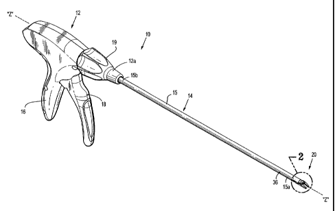
[0019] FIG. 1 is a perspective view of a surgical clip applier in accordance
with
the present disclosure;
[0020] FIG. 2 is an enlarged perspective view of a distal end of the clip
applier of
FIG. 1, illustrating a jaw assembly thereof;
[0021] FIG. 3 is a bottom, perspective view of the surgical clip applier of
FIG. 1,
illustrating a drive assembly including a locking cam driver and the jaw
assembly
thereof,
[0022] FIG. 4 is an enlarged area of detail of FIG. 3;
[0023] FIG. 5 is a bottom, perspective view of the jaw assembly shown in an
open configuration;
[0024] FIG. 6 is a top, perspective view of the jaw assembly of FIG. 5;
[0025] FIGS. 7 and 8 are front, perspective views of the locking cam driver
illustrated in FIGS. 3 and 4;
[0026] FIG. 9 is a bottom, perspective view illustrating the locking cam
driver
assembly actuating the jaw assembly to an approximated, substantially closed
configuration;
-5-
CA 02763165 2012-01-05
[0027] FIG. 10 is a front, cross-sectional, perspective view of the locking
cam
driver taken along lines 10-10, as shown in FIG. 7;
[0028] FIG. 11 is a front, cross-sectional, perspective view the jaw assembly
taken along lines 11-11, as shown in FIG. 6;
[0029] FIG. 12 is a front, cross-sectional, perspective view illustrating the
locking
cam driver actuating the jaw assembly taken along lines 12-12, as shown in
FIG. 9; and
[0030] FIG. 13 is a perspective view of a surgical clip formed on a vessel.
DETAILED DESCRIPTION
[0031] Embodiments of surgical clip appliers in accordance with the present
disclosure will now be described in detail with reference to the drawing
figures wherein
like reference numerals identify similar or identical structural elements. As
shown in the
drawings and described throughout the following description, as is traditional
when
referring to relative positioning on a surgical instrument, the term
"proximal" refers to the
end of the apparatus which is closer to the user and the term "distal" refers
to the end of
the apparatus which is further away from the user.
[0032] There is disclosed a novel endoscopic surgical clip applier including a
drive assembly having, amongst other things, a locking cam driver that is
configured to
approximate jaw members of a jaw assembly into a substantially closed
position. The
locking cam driver includes angled camming surfaces that cam along
corresponding
substantially complementary angled camming surfaces of the jaw assembly. The
angled
camming surfaces of both the locking cam driver and the jaw assembly are
configured to
-6-
CA 02763165 2012-01-05
slidingly engage, while locking within each other, in a camming manner. It
should be
noted that, while the presently disclosed locking cam driver is shown and
described with
in an endoscopic surgical clip applier, the disclosed locking cam driver and
its features
may be applicable to any surgical clip applier or any other surgical
instrument having a
compressible jaw assembly.
[0033] Referring now to FIG. 1, a surgical clip applying instrument or
surgical
clip applier 10 is shown including a handle assembly 12 and an endoscopic
portion 14.
Endoscopic portion 14 includes an elongated tubular member 15 that extends
distally
from handle assembly 12. Handle assembly 12 includes a stationary handle 16
and a
pivoting or movable handle 18. Manipulation of handle 18 relative to handle 16
actuates
a jaw assembly 20, which is operably coupled to a distal end 15a of elongated
tubular
member 15 or endoscopic portion 14. More specifically, jaw assembly 20 is
actuated by
a plurality of components of a drive assembly, which will be discussed in more
detail
below. Handle assembly 12 may be made from any suitable thermoplastic
material, and
elongated member 15 may be made from any suitable biocompatible material, for
example, but not limited to stainless steel, titanium or any suitable plastic
material.
[0034] In embodiments, a rotating knob 19 is rotatably mounted on a distal end
12a of handle assembly 12. Rotating knob 19 is operably coupled to elongated
tubular
member 15 of endoscopic portion 14 to provide remote rotation (e.g., 360 of
rotation) of
elongated tubular member 15 and jaw assembly 20 along a longitudinal center
axis "Z-Z"
defined by elongated tubular member 15.
-7-
CA 02763165 2012-01-05
[0035] Clip applier 10 is configured to retain one or more surgical clips "C"
for
application to a desired tissue or vessel "V," as shown in FIG. 13. Clip
applier 10 has an
elongated clip channel member (not shown) that is disposed within elongated
tubular
member 15 for retaining a number of surgical clips "C." As shown in FIG. 2,
clip applier
includes a nose 66 to direct the clips "C" traversing through the clip channel
member
(not shown) into channels 28a and 28b of jaw members 26a and 26b of jaw
assembly 20.
Jaw assembly 20 and its components will be discussed in greater detail below.
[0036] Referring now to FIGS. 3 and 4, the present surgical clip applier 10
includes various components, which will be briefly discussed, in order to
actuate jaw
assembly 20 to form a closed clip "C" (FIG. 13) therebetween. A detailed
discussion of
the structure, operation, and method of assembly of various components
surgical clip
applier 10 is disclosed in commonly owned U.S. Patent No. 5,700,271 to
Whitfield et al.,
entitled "Apparatus For Applying Surgical Clips" and U.S. Patent Application
Publication No. 2006/0085015 to Whitfield et al., entitled "Endoscopic
Surgical Clip
Applier," the entire contents of each of which is incorporated herein by
reference.
[0037] In embodiments, clip applier 10 may include a wedging mechanism (not
shown) to perform a wedging function that is provided to maintain jaw assembly
20 in a
spaced apart condition for loading clip "C" within jaw assembly 20. Once jaw
assembly
is loaded with clip "C," the wedging mechanism is retracted out of jaw
assembly 20 to
allow approximation of jaw members 20a and 20b by various components of a
drive
assembly. In embodiments, clip applier 10 may also include a feeding mechanism
(not
-8-
CA 02763165 2012-01-05
shown) for feeding a single clip "C" into jaw assembly 20, at a distal portion
15a of
elongated tubular member 15, during a single firing stroke of clip applier 10.
[0038] Referring still to FIGS. 3 and 4, the drive assembly of surgical clip
applier
includes an actuation mechanism 60 that operates to pass through the elongated
tubular member 15 to thereby actuate a locking cam driver 50 to close jaw
assembly 20
and fully form clip "C". More specifically, actuation mechanism 60 is
translated in a
longitudinally distal and proximal direction through the elongated tubular
member 15. A
distal portion of actuation mechanism 60 includes a drive assembly having
locking cam
driver 50 and a slider joint 62 that both extend from the distal end of
actuation
mechanism 60 to selectively engage camming surfaces 40a and 40b provided on
jaw
assembly 20, which thereby approximate or close jaw members 26a and 26b around
a
preloaded surgical clip "C." Actuation mechanism 60 may be operably coupled to
locking cam driver 50 via slider joint 62. Actuation mechanism 60, slider
joint 62, and
locking cam driver 50 are all disposed within elongated tube 15. As will be
discussed in
greater detail below, actuation of locking cam driver 50 closes the jaw
assembly 20 to
compress or form a clip "C" that is held therebetween.
[0039] With reference to FIGS. 5 and 6, jaw assembly 20 and its components
will
now be discussed in detail. As discussed above, jaw assembly 20 is positioned
on distal
end 15a of tubular member 15, and includes juxtaposed jaw members 26a and 26b.
Both
jaw members 26a and 26b are simultaneously movable between a spaced
configuration,
in which jaw members 26a and 26b are separated at least a sufficient distance
defined by
a space 24, to receive a surgical clip "C" therebetween, and an approximated,
-9-
CA 02763165 2012-01-05
substantially closed configuration, in which jaw members 26a and 26b are in
relatively
close relation to one another to form a surgical clip "C" around a vessel "V,"
as shown in
FIG. 13, that has been positioned within surgical clip "C." Each jaw member
26a and
26b has an elongated channel 28a and 28b, respectively, for receipt of a
single surgical
clip "C" therein. Surgical clip "C" may be applied or placed in elongated
channels 28a
and 28b by a loading structure of clip applier 10 to apply surgical clip "C"
in, for
example, a body cavity. Jaw assembly 20 may be made from a suitable
biocompatible
material, for example, but not limited to stainless steel, titanium or a
suitable alloy.
[0040] Jaw assembly 20 further includes elongated flexible legs 22a and 22b
connected at distal base portion 22c. Flexible legs 22a and 22b are resilient
to permit
relative approximation and spacing of juxtaposed jaw members 26a and 26b. As
discussed above, elongated channels 28a and 28b are provided on or in the
juxtaposed
inner surfaces of jaw members 26a and 26b for reception of a surgical clip
"C."
[0041] In an embodiment, jaw assembly 20 may further include locking legs 30a
and 30b connected at proximal base portion 34, each having a radially
outwardly
extending tab 34a and 34b, respectively, formed thereon. Tabs 34a and 34b are
configured to engage corresponding holes 36 defined on elongated tube 15 (FIG.
1) to
secure jaw assembly 20 to elongated tube 15. It is contemplated that jaw
assembly 20
may be secured to elongated 15 in any manner known by one having skill in the
art.
[0042] As depicted in FIG. 5, each of jaw members 26a and 26b includes raised
elements 38a and 38b, respectively, formed on a bottom surface thereof. In
order to
provide increased closing force, camming surfaces 40a and 40b are disposed on
an outer
-10-
CA 02763165 2012-01-05
surface of each of raised elements 38a and 38b, respectively, to facilitate
closure of jaw
members 26a and 26b of jaw assembly 20. Camming surfaces 40a and 40b each
define
an angle "(3" relative to a horizontal axis "X-X" defined by jaw members 26a
and 26b
(FIG. 11) to correspond with substantially complementary angled camming
surfaces of
locking cam driver 50, which will be described in greater detail below.
[0043] Turning now to FIGS. 7 and 8, locking cam driver 50 has a hemispherical
configuration that includes a flat, top surface 56 that engages (or is
adjacent) jaw
assembly 20 and a curved portion (e.g., semi-circular) 58 (FIG. 9) that
engages (or is
adjacent) an inner portion of elongated tubular member 15.
[0044] At a proximal portion, locking cam driver 50 includes a T-shaped recess
59 that is configured to receive a distal T-shaped end 64 of slider joint 62.
It should be
noted that other types of connecting configurations may be utilized to connect
locking
cam driver 50 to slider joint 62. For example, locking cam driver 50 may be
connected to
slider joint 62 by crimping, welding, bolting, and adhering.
[0045] At a distal portion, locking cam driver 50 includes a bifurcated
configuration having a pair of spaced apart angled camming surfaces 52a and
52b that
surround and define a U-shaped space 54 that is dimensioned and configured to
receive
corresponding substantially complementary angled camming surfaces 40a and 40b
of jaw
assembly 20. More particularly, distal movement of locking cam driver 50 moves
camming surfaces 52a and 52b thereof with respect to and against camming
surfaces 40a
and 40b of raised elements 3 8a and 38b to thereby move jaw members 26a and
26b from
the un-approximated, open position into the approximated, substantially closed
position.
-11-
CA 02763165 2012-01-05
When jaw members 26a and 26b are moved to the approximated, substantially
closed
position, a clip "C" is formed when positioned within elongated channels 28a
and 28b of
jaw assembly 20, as shown in FIG. 13.
[0046] Referring now to FIGS. 9-12, during use, handle 18 of handle assembly
12
(FIG. 1) is actuated toward handle 16, to a closed position. During actuation
of handle
18, the driving assembly of clip applier 10 moves actuation mechanism 60,
slider joint
62, and locking cam driver 50 in a distal direction, as depicted by
directional arrow "A"
of FIG. 9.
[0047] As discussed above, during distal movement of locking cam driver 50
relative to jaw assembly 20, camming surfaces 52a and 52b of locking cam
driver 50
engage camming surfaces 40a and 40b of jaw members 26a and 26b. In this
manner, jaw
members 26a and 26b are gradually brought into approximation with distal
movement of
locking cam driver 50. More particularly, since raised elements 38a and 38b
are wider at
the distal portion than at the proximal portion, progressive distal movement
of U-shaped
locking cam driver 50 cams jaw members 26a and 26b towards an approximated,
closed
position, as depicted by direction arrows "B" of FIG. 9. The proximity of
locking cam
driver 50 and raised elements 38a and 38b to the distal portion of jaw members
26a and
26b enables sufficient force to be exerted on jaw members 26a and 26b to
deform clip
"C" and compress blood vessels or other body tissue surrounded thereby.
[0048] Turning now specifically to FIGS. 10-12, and initially to FIG. 10,
camming surfaces 52a and 52b of locking cam driver 50 are configured to define
predetermined acute angles "a" relative to a horizontal plane defined by axes
"X-X" and
-12-
CA 02763165 2012-01-05
"Z-Z." Camming surfaces 52a and 52b form predetermined acute angles "a"
oriented
towards space 54 (e.g., towards a center of locking cam driver 50) to provide
a capturing
configuration. As shown in FIG. 11, camming surfaces 40a and 40b of raised
elements
38a and 38b of jaw members 26a and 26b are configured to define predetermined
acute
angles "P" relative to a horizontal plane defined by axes "X-X" and "Z-Z." In
an
opposite manner, with comparison to camming surfaces 52a and 52b of locking
cam
driver 50, camming surfaces 40a and 40b of raised elements 38a and 38b form
predetermined acute angles "P" oriented towards an outer edge of jaw assembly
20 (e.g.,
away from the center of jaw assembly 20). In accordance with the present
disclosure, the
plane defined by axes "X-X" and "Z-Z" may also be represented by the plane
defined by
flexible legs 22a and 22b of jaw assembly 20 and/or by top surface 56 of
locking cam
driver 50.
[0049] During actuation of locking cam driver 50 along the jaw assembly 20, as
depicted in FIG. 12, the angled camming surfaces 52a and 52b of locking cam
driver 50
engage and lock with corresponding angled camming surfaces 40a and 40b to
prevent
locking cam driver 50 from disengaging from jaw assembly 20. By providing
angled
camming surfaces 52a and 52b of locking cam driver 50 and angled camming
surfaces
40a and 40b of jaw assembly 20, locking cam driver 50 and jaw assembly 20
interlock
with each other so that during actuation, locking cam driver 50 is drawn
towards jaw
assembly 20 to provide more closure force. The angled configuration also
maintains jaw
members 26a and 26b in alignment with each other (e.g., along the "X-X" axis),
which
prevents clips "C" from twisting during formation.
-13-
CA 02763165 2012-01-05
[0050] In embodiments, predetermined angles "a" of camming surfaces 52a and
52b of locking cam driver 50 and predetermined angles "[3" of camming surfaces
40a and
40b of jaw assembly 20 may have different degree values to provide an offset
angled
configuration. More particularly, predetermined angles "a" may be a relatively
smaller
angle (e.g., 30 degrees) than predetermined angles "[3" (e.g., 45 degrees).
The offset
angled configuration facilitates pulling of the locking cam driver 50 towards
jaw
assembly 20 to provide a greater force while closing jaw assembly 20 and to
prevent
locking cam driver 50 from disengaging from jaw assembly 20 during actuation.
The
offset angled configuration also reduces surface-to-surface friction between
camming
surfaces 40a and 40b and camming surfaces 52a and 52b, respectively, since the
planes of
each corresponding camming surfaces are offset because of the difference in
the degree
values for angles "a" and "R."
[0051] During a manufacturing process, the angled camming surfaces 40a and
40b of respective jaw members 26a and 26b can be machined in a one-step
process.
More particularly, an angled cutter head may be used to cut the angled camming
surface
40a and 40b along the side of raised elements 38a and 38b, respectively.
[0052] It should be understood that the foregoing description is only
illustrative
of the present disclosure. Various alternatives and modifications can be
devised by those
skilled in the art without departing from the disclosure. Accordingly, the
present
disclosure is intended to embrace all such alternatives, modifications and
variances. The
embodiments described with reference to the attached drawing figures are
presented only
to demonstrate certain examples of the disclosure. Other elements, steps,
methods and
-14-
CA 02763165 2012-01-05
techniques that are insubstantially different from those described above
and/or in the
appended claims are also intended to be within the scope of the disclosure.
15-