Note: Descriptions are shown in the official language in which they were submitted.
CA 02763379 2011-11-24
WO 2010/135802 PCT/CA2009/000775
08914110WO
MOBILE SELF-CONTAINED STONE-MAKING AND CONCRETE-
PROCESSING FACTORY
CROSS-REFERENCE TO RELATED APPLICATIONS
[0001] This is the first application filed for the present
invention.
TECHNICAL FIELD
[0002] The present invention relates generally to stone-
making and concrete-processing factories and, in particular,
to mobile stone-making and concrete-processing factories.
BACKGROUND
[0003] Traditionally, building blocks, stones, bricks,
pavers, interlock, cladding and the like are constructed at a
factory and transported to the construction site for assembly.
Due to the substantial weight and bulk of these blocks,
stones, bricks, etc., the transport costs are high, thus
increasing the overall cost of the building. Where the
construction site is remote, and thus far from the factory,
the transport costs can become prohibitively high.
[0004] Some attempts have been made to develop mobile
factories that can be brought to the construction site to
minimize construction costs. Some examples are the
technologies disclosed in U.S. Patent 4,725,216 (Foster), U.S.
Patent 5,785,420 (Schuff), U.S. Patent 4,569,649 (Gross), PCT
International Publication WO 2007/115233 (Jennings) and
Japanese Patent Application JP 10323812A2 (Ushigome).
[0005] With respect to the Foster reference, this prior-art
machine does not have a separate receptacle for receiving
local aggregate that is distinct from the batching or mixing
-1-
CA 02763379 2011-11-24
WO 2010/135802 PCT/CA2009/000775
08914110WO
chamber. The Foster reference describes loading raw materials
directly into the mixing chamber.
[0006] With respect to the Schuff reference, there is no
compression station for forming blocks.
[0007] With respect to the Gross reference, this is merely a
machine for forming compressed earth blocks, similar to WO
2007/115233 (Jennings), in that there is no batching module
for mixing the aggregate with cementitious material and water.
[0008] With respect to the Ushigome reference, this machine
is only a press machine carried by a trailer. There is no
aggregate receptacle and distinct batching module.
[0009] Therefore, until the invention of the mobile factory
described and claimed in the present application, there did
not exist a fully portable and self-contained machine capable
of manufacturing blocks and stone products onsite from local
aggregate. This invention represents a radically new approach
to the onsite making of stone products.
SUMMARY
[0010] In broad terms, the present invention is a novel
mobile, self-contained stone-making and cement-forming
factory. This mobile factory comprises, in general, four main
components, namely (1) a power plant, (2) a receptacle for
receiving local aggregate, (3) a batching module for mixing
aggregate with cementitious material and water and for feeding
the batch to a compression station and (4) the compression
station for compressing the batch into a stone, block, or
brick.
[0011] Unlike all pre-existing machines known to the
applicant, this novel mobile factory is entirely self-
contained and enables blocks, bricks or stones to be
-2-
CA 02763379 2011-11-24
WO 2010/135802 PCT/CA2009/000775
08914110WO
manufactured on site using local aggregate. This new
technology revolutionizes building practices since blocks,
bricks, stones, and the like can be easily, efficiently and
inexpensively manufactured on site, thus entirely obviating
the need to transport building blocks, brick and stones to the
construction site.
[0012] This mobile factory (portable machine) can be used to
produce a wide variety of different stones such as, for
example, pavers, cladding, interlock, retaining wall stones,
building blocks, patio stones, curb and step stones, custom
stones and other types of bricks. Optionally, the machine may
include a mortar pump that can be used for producing pre-casts
and for spray-on application of mortar to work areas.
[0013] In main embodiments of the invention, the mobile
factory is a trailer-mounted machine that can be towed by a
utility vehicle, off-road vehicle, truck, pickup truck, or
other vehicle. The machine is entirely self-contained as it
has its own power plant or engine for driving a compression
system for compression forming of stones, blocks or bricks.
Although the main embodiment of the machine, as illustrated in
the attached figures, is a trailer-mounted factory, it is to
be expressly understood that the machine (mobile factory)
could also be mounted directly on a flatbed truck, boat,
barge, train car, or any other type of vehicle. In a variant,
the power plant of the mobile factory may be shared with the
vehicle or a power takeoff (PTO) may be used to drive either
the compression station or to provide propulsion for the
vehicle.
[0014] Accordingly, one main aspect of the present invention
is a mobile factory comprising a portable frame for supporting
the mobile factory and for enabling the mobile factory to be
displaced to a construction site, a receptacle for receiving
-3-
CA 02763379 2011-11-24
WO 2010/135802 PCT/CA2009/000775
08914110WO
local aggregate, a batching module for mixing the local
aggregate with cementitious material and water to thereby
create a batch, a compression station for compressing the
batch into a stone product, and a power plant for powering the
batching module and the compression station.
[0015] In one set of embodiments of this invention, a pair of
removable compression plates is inserted into a compression
chamber of the compression station to produce customized
surface finishes on two sides of the stone product when the
stone product is compressed in the compression chamber.
[0016] In another set of embodiments of this invention, the
batching module comprises a measuring module for receiving
aggregate and a mixer disposed beneath the measuring module,
the mixer having mixing paddles equipped with wear bars. A
mixer-lifting cylinder may be provided for lifting the mixer
from a batch-mixing position posture to a batch-dispensing
posture. The paddles act to dispense the batch from the mixer
when the mixer is in the batch-dispensing posture.
[0017] In yet another set of embodiments of this invention,
the mobile factory optionally comprises a guillotine for
shearing stone products produced by the compression station,
the guillotine being connected to a compression cylinder of
the compression station.
[0018] The mobile factory may also optionally include a PSI
testing adapter, the PSI testing adapter being driven by a
compression cylinder of the compression station. This PSI
testing adapter may be connected to the guillotine.
[0019] A further main aspect of the present invention is a
method of onsite manufacturing of stone products and
processing of cement. The method entails transporting a
mobile self-contained stone-making and cement-processing
-4-
CA 02763379 2011-11-24
WO 2010/135802 PCT/CA2009/000775
08914110WO
factory to a construction site, powering the mobile factory
using an onboard power plant, loading local aggregate into a
receptacle of the mobile factory, batching the local aggregate
with water and cementitious material, compressing the batch in
a compression chamber to produce a stone product, and
extracting the stone product from the compression chamber.
[0020] A related aspect of this novel technology is an
innovative method of producing stone products with patterned
faces on two opposing sides. This novel method entails
inserting a first patterned compression plate into a
compression chamber, inserting a second patterned compression
plate into the compression chamber, dispensing a batch from a
mixer into the compression chamber, compressing the batch in
the compression chamber to form a stone product, and
separating the first and second patterned compression plates
from the stone product after a predetermined period of time
has elapsed to reveal patterned faces on the stone product.
The patterned compression plates can be identical or
different. This technology enables efficient onsite
production of stone products with one or two customized faces
bearing any desired designs, letters, symbols, logos, etc. As
a corollary advantage of using these compression plates, the
moisture content can be increased beyond what would normally
be employed to produce much finer detail and smoother surface
finishes. These effects can be achieved without operating at
very high compaction pressures, thus prolonging the service
life of the machine.
[0021] Other aspects, features and advantages of this novel
technology will become apparent with reference to the
following description and drawings.
-5-
CA 02763379 2011-11-24
WO 2010/135802 PCT/CA2009/000775
08914110WO
BRIEF DESCRIPTION OF THE DRAWINGS
[0022] Further features and advantages of the present
invention will become apparent from the following detailed
description, taken in combination with the appended drawings,
in which:
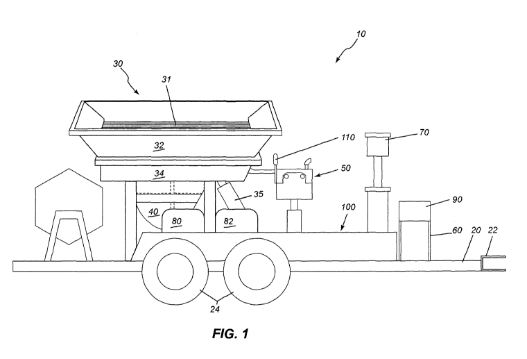
[0023] FIG. 1 is a left-side elevation view of the mobile
factory in accordance with one embodiment of the present
invention;
[0024] FIG. 2 is a right-side elevation view of the mobile
factory introduced in FIG. 1;
[0025] FIG. 3 is a frontal perspective view of the mobile
factory, showing the compression chamber with the door locked
down, as well as the product removal tray;
[0026] FIG. 4 is a rear perspective view of the mobile
factory, showing the tumbler and the hopper lifting cylinders;
[0027] FIG. 5 is a rear perspective view of the mobile
factory, showing the upper hopper tipped to extract oversized
materials;
[0028] FIG. 6 is a right-side elevation view of the mobile
factory, showing the mixer lifted by the hydraulic cylinders
into the material-dispensing mode;
[0029] FIG. 7A depicts the first step in a typical loading
sequence in which the mobile factory is positioned for
loading;
[0030] FIG. 7B depicts the second step in the loading
sequence in which local aggregate is dumped into the hopper
from a tractor bucket;
-6-
CA 02763379 2011-11-24
WO 2010/135802 PCT/CA2009/000775
08914110WO
[0031] FIG. 7C depicts the third step in the loading sequence
in which excessively large material is ejected after
screening;
[0032] FIG. 7D depicts the fourth step in the loading
sequence in which the hopper measure module is filled;
[0033] FIG. 7E depicts the fifth step in the loading sequence
in which the batcher bottom is opened to empty the material
into the mixer;
[0034] FIG. 7F depicts the sixth step of mixing the batch
using a hydraulically reversible four-paddle mixer;
[0035] FIG. 7G depicts the seventh step of dispensing mixed
material onto the material-holding slide and into the
compression chamber;
[0036] FIG. 8A depicts the compression chamber in a first
mode in which it is ready to receive material for compacting
into product;
[0037] FIG. 8B depicts the compression chamber in a second
mode in which the guillotine is affixed;
[0038] FIG. 8C depicts the compression chamber in a third
mode in which the PSI testing adapter is bolted to the
guillotine;
[0039] FIG. 9 depicts the threaded pins for scribing product
during manufacture or for prepping the block for subsequent
shearing;
[0040] FIG. l0A depicts the block extractor and material
levelling device with the twin-handle extractor retracted;
[0041] FIG. 10B depicts the block extractor and material
levelling device with the twin-handle extractor extended;
-7-
CA 02763379 2011-11-24
WO 2010/135802 PCT/CA2009/000775
08914110WO
[0042] FIG. 10C depicts the block extractor and material
levelling device with the twin-handle extractor retracted
during a compression cycle; and
[0043] FIG. 11 depicts three different types of reusable
injection-molded plates that enables the manufacture of a wide
variety of double-faced stone products.
[0044] It will be noted that throughout the appended
drawings, like features are identified by like reference
numerals. It should furthermore be noted that the drawings
are not necessarily to scale.
DETAILED DESCRIPTION
[0045] In general, and by way of overview, the present
invention provides a mobile, self-contained factory for not
only making stones, blocks, compressed earth blocks, pavers,
tiles, and other such stone products but also for processing
cement. In its broadest conception, the novel mobile factory
comprises four main components mounted on a trailer or other
such mobile or portable frame, namely (1) a power plant or
engine, (2) a receptacle for receiving local aggregate, (3) a
batching module for mixing aggregate with cementitious
material and water, and (4) a compression station for
receiving the batch and for compressing the batch into a
stone, block, brick, paver, interlock, tile, or other such
product. This novel machine enables a new method of
manufacturing stone products. As will be elaborated below,
this innovative technology revolutionizes the construction
industry by enabling builders to manufacture stone products
onsite using local aggregate, thus dramatically reducing
construction costs.
[0046] Main illustrative embodiments of this invention are
now described below having regard to the appended figures.
-8-
CA 02763379 2011-11-24
WO 2010/135802 PCT/CA2009/000775
08914110WO
Described below are the novel mobile factory, the novel
methods and the various products that can be made using this
mobile factory and the related methods.
[0047] MOBILE FACTORY
[0048] FIG. 1 is a left-side elevation view of the mobile
factory in accordance with one embodiment of the present
invention. This figure depicts a mobile factory generally
designated by reference numeral 10 comprising a portable frame
20 (e.g. a trailer or equivalent) for supporting the mobile
factory and for enabling the mobile factory to be displaced
(e.g. towed) to a construction site. The mobile factory also
comprises a receptacle 30 (e.g. a movable hopper with
aggregate screening) for receiving local aggregate. The
mobile factory also includes a batching module 40 (e.g. that
includes a measuring module and mixer) for mixing the local
aggregate with cementitious material and water to thereby
create a batch. The mobile factory further includes a
compression station 50 (e.g. with hydraulically operable
compression cylinder) for compressing the batch into a stone
product. A power plant 60 (e.g. a diesel engine) is provided
on the mobile frame for powering the batching module and the
compression station. Thus constituted, this novel mobile
factory is an entirely self-contained and self-sufficient
stone-making machine. In addition, the mobile factory has a
number of additional innovative features (e.g. custom-
patterned compression plates and mortar pump, to name but two
of the principal ones) that will also be introduced below.
These additional features facilitate the task of manufacturing
stone products and processing cement.
[0049] FIG. 1 shows a trailer-mounted mobile factory. The
trailer may be a standard roadworthy trailer having a trailer
hitch coupling 22 in the front, a plurality of wheels 24 with
-9-
CA 02763379 2011-11-24
WO 2010/135802 PCT/CA2009/000775
08914110WO
tires, brake-lights in the back, reflectors, etc. The
particular version of the mobile factory illustrated in this
application can easily be towed by a small utility vehicle or
a pickup truck, for example. Simple vertically extending feet
may be lowered from the frame to the ground and secured (e.g.
with locking pins) to stabilize the machine during operation.
Alternatively, screw-operated or hydraulic stabilizers can be
provided on the trailer to stabilize the machine during
operation.
[0050] FIG. 1 shows that the power plant 60 of the mobile
factory, in this particular case, is a removable diesel engine
that can be removed from the frame and operated at a distance
from the frame in order to reduce noise and vibration for the
operator. This can be accomplished easily by quick-coupled
hydraulic hoses to any desired length up to 50 ft
(approximately 15.5 metres), beyond which pressure losses in
the hydraulic lines begin to discernibly degrade hydraulic
power. The diesel engine can be controlled by a control
console shown in FIG. 1. A diesel fuel tank may be provided
on the trailer to supply fuel to the diesel engine via a
suitable fuel line. Other types of engines can be
substituted.
[0051] FIG. 1 shows how a top portion of a hopper or "hopper
top" (i.e. that is part of the receptacle 30 introduced above)
can be easily loaded with local aggregate using a mechanical
backhoe, front-end loader, tractor or even by manual labour
(i.e. a person shovelling in the aggregate). As is well known
in the art, the aggregate may include rock, crushed stone,
gravel, sand, slag, etc., or combinations thereof.
[0052] As depicted in FIG. 1, a vibrating aggregate screen 31
(having a variably sized mesh) disposed inside the movable
hopper top 32 can be used to separate larger unwanted
-10-
CA 02763379 2011-11-24
WO 2010/135802 PCT/CA2009/000775
08914110WO
particles or "chunks" of aggregate from the useable aggregate.
This vibrating aggregate screen can be vibrated using an
attached vibrator 33 (shown in FIGS. 2 and 3) that, in turn,
can be operated via remote control from the tractor operator's
station. The sifted aggregate will fall by gravity into the
hopper bottom aggregate storage compartment 34 for storage and
later use (i.e. into the bottom portion of the receptacle).
The top portion of the hopper can be tilted (pivoted) by way
of a hydraulic cylinder 35 (or equivalent) to eject (i.e.
dump) the unwanted larger chunks of aggregate back onto the
ground. The hydraulic cylinder that tilts the movable hopper
top can be controlled from the control console 70 shown in
FIG. 1. Accordingly, this novel machine allows local
aggregate to be used in the production of stone products, thus
saving the cost of handling and transport.
[0053] FIG. 1 also shows the water tank 80 for the storage of
wash-down and clean-up water, which is connected to a water
pressure pump (not shown) and a nozzled hose (also not shown)
which is accessible near the control console. Also, this
water tank stores the water (moisture) needed for the
aggregate and cement (or cementitious material). A water and
add mixture tank 82 may also be provided. An add mixture to
help repel water and assist in compaction may also be added,
as required by the operator in order to produce different
types of stone product. Other chemical admixtures may also be
added as required and carried with the mobile factory (e.g.
accelerators, retarders, plasticizers, pigments, air
entrainments, bonding agents, etc.). This figure also shows
the hydraulic fluid storage 90 coupled to, or otherwise
disposed above, the diesel engine.
[0054] All machinery and accessories, with the exception of
the hopper screening device, tumbler and mortar pump, which
can be operated by remote control as well, are controlled from
-11-
CA 02763379 2011-11-24
WO 2010/135802 PCT/CA2009/000775
08914110WO
the central control console 70 depicted in FIG. 1. This
control console is ergonomically disposed immediately beside
the operator platform 100. During stone production
operations, the operator typically stands on the operator
platform so as to be within easy reach of the control console
and also the block-extractor handles 110. A sunshade or
parasol (not shown) can be provided on a stand mounted to the
portable frame to provide shade for the operator. This
sunshade may be foldable for when the trailer is being towed.
All hydraulics are controlled electronically with the
exception of the mixer-lifting hydraulic cylinder and the
mixer paddles. The latter are stick-controlled because better
control can be achieved by manipulating stick-controlled
hydraulic valves. The mixer height can be adjusted more
precisely and the amount of batch material extracted into the
compression chamber via the mixing paddles can be regulated
and controlled more accurately with stick-controlled hydraulic
valves. Also, the amount of moisture injection into the
aggregate can be controlled by a timer from this station
(control console). For safety reasons, the operator is
required to hold the button (switch) that lowers the
compression chamber lid, locks the lid and initializes the
block forming. Requiring the operator to hold this button
(switch) down prevents fingers and limbs from being injured.
In a variant, two buttons (switches) are provided, thus
requiring both hands to be fully occupied when the lid is
closed and locked and the block compacted. It should be noted
that this compression chamber lid is a hydraulically operated
lid that has an inline throttle to control the speed of both
upward movement and downward movement, i.e. both the opening
and closing actions of the lid.
[0055] FIG. 2 is a right-side elevation view of the mobile
factory introduced in FIG. 1. FIG. 2 shows the aggregate
-12-
CA 02763379 2011-11-24
WO 2010/135802 PCT/CA2009/000775
08914110WO
dispensing chute 36. When raised, this chute funnels the
aggregate stored in the bottom of the hopper into the
measuring module 41 (that forms part of the batching module
40). On top of this chute 36 is the hydraulic removable
remote-controlled vibrating device (vibrator 33), which can
vibrate the chute to assist gravity with the sliding down the
chute of the stored aggregate. In other words, the vibrator
33 is not only useful for vibrating the vibrating aggregate
screen (as described earlier) for sifting the loaded aggregate
but is also useful in shaking the chute 36 to help the
aggregate fall into the measuring module 41. The sliding
aggregate material fills the measuring module 41 on top of the
mixer 42. It is then possible to add a desired percentage of
pre-packaged cement and optional colorant. This allows
accurate, repetitious batching to ensure desired strength and
color consistency. Directly in front of the measuring module
is the moisture injection nozzle 43. This nozzle 43 sprays
the aggregate with water and add mixture if desired, while the
various constituents in the mixer 42 are being agitated. This
nozzle 43 is located in the material outlet opening 44. The
mixer 42 has four arms 45 and paddles which are rotated by an
extremely powerful hydraulic motor. On the end of the paddles
are wear plates 45a (also known as wear pads or wear bars),
which can be adjusted to keep close tolerance with the contour
of the interior of the mixer. Such an arrangement ensures
rapid yet thorough mixing. Once mixed, the batch is
transferred to the compression station 50, i.e. into a
compression chamber 51 for compaction of the batch into a
block or stone product using a hydraulically powered
compression cylinder 52.
[0056] As also shown in FIG. 2, the compression station 50
has a compression chamber lid 53 (i.e. a compression chamber
cover) that includes locking pins 54 that hydraulically lock
-13-
CA 02763379 2011-11-24
WO 2010/135802 PCT/CA2009/000775
08914110WO
the compression chamber lid in place, allowing it to withstand
the extreme pressure required to form the product.
[0057] As further depicted in FIG. 2, the mobile factory may
also be configured to act as a mortar pump for delivering
mortar. The compression station includes a mortar pump hose
connection 120 to which a mortar-delivery hose (not shown) can
be connected. The mortar pump hose connection 120 is situated
in this particular version of the machine at the top of the
compression chamber. To deliver mortar, a mortar slurry is
mixed in the mixer 42. When the mixer 42 is elevated, the
mortar slurry travels down the material holding slide 130 and
into the compression chamber. The movable bottom of the
compression chamber 51 has been sealed with a travelling
gasket plate (not shown). As well, the top lid has a sealing
gasket (also not shown). When the compression chamber is
filled with mortar slurry, the lid is closed, sealed and
locked. When the compression cylinder is activated upwards,
the only outlet for the mortar slurry is through the mortar
pump hose connection 120 and into the mortar hose (not shown).
This outlet can be connected to a hose for delivering mortar
for many different functions and applications, such as, for
example, to fill in and strengthen brick and stone walls or
other structures. This is particularly useful for awkward,
hard-to-reach places, e.g. back yards, where large
conventional equipment cannot pass. The mortar pump can also
be used for spraying of stucco. The mortar can also be used
for the injection of molds for the forming of mortar-based
products, e.g. roof tiles. For this application, special
plastic molds are carried with the mobile factory to enable
the roof tiles or other mortar-based products to be produced
onsite.
[0058] FIG. 3 is a frontal perspective view of the mobile
factory, showing the compression chamber with the lid/door 53
-14-
CA 02763379 2011-11-24
WO 2010/135802 PCT/CA2009/000775
08914110WO
locked down, as well as the product removal tray 140. The
finished product is slid out onto this product removal tray
140 for removal. FIG. 3 also shows the aggregate screening
compartment (hopper top) 32 with attached vibrator 33, the
aggregate storage compartment (hopper bottom) 34 and its
adjacent aggregate dispensing chute 36. The lifting cylinders
35 tilt these hoppers 32, 34 from the posture illustrated in
FIG. 3 to a posture in which the dispensing chute 36 is above
the batching module 40 whereupon the aggregate is dispensed
through the chute 36 into the batching module 40 (in
particular into the measuring module 41). The outlet of the
measuring module 41 is then opened to deliver a measured
amount of aggregate into the mixer 42 below. The mixer 42
used its hydraulically driven paddles to mix the batch with
water and cementitious material. It should be noted that
cementitious material is not used for a compressed earth
block. Thereafter, the batch is delivered via the material
slide 48 to the compression chamber. The compressed block is
then extracted and disposed on the product removal tray 140
(the small platform that extends outwardly from the
compression station). Also visible in this figure are the
wash-down water tank 80, water and add mixture tank 82,
hydraulic fluid storage 90, removable engine pack 60, trailer
hitch coupler 22 and control console 70.
[0059] FIG. 4 is a rear perspective view of the mobile
factory, showing a tumbler 150 and the hopper-lifting
cylinders 35. The tumbler 150 shown on the back is a rotating
drum into which the product is placed for tumbling. This
tumbling creates different product effects and looks, such as
rounded or smooth edges and an old-stone appearance. As shown
in FIG. 4, the machine includes an aggregate screening
compartment 32, an aggregate storage compartment 34, a
vibrator 33, an aggregate dispensing chute 36, a measuring
-15-
CA 02763379 2011-11-24
WO 2010/135802 PCT/CA2009/000775
08914110WO
module 41, a mixer 42 and a control console 70. For the
purposes of this specification, the term "receptacle" (which
is generally designated by reference numeral 30) is meant to
include both the top and the bottom hoppers (i.e. both the
aggregate screening compartment 32 and the aggregate storage
compartment 34 as well as the aggregate dispensing chute 36).
For the purposes of this specification, the expression
"batching module" (which is generally designated by reference
numeral 40) is meant to include both the mixer 42 and the
measuring module 41.
[0060] FIG. 4 also shows how the frame 20 of the mobile
factory may have a bay-shaped opening 152 at one end to
provide a space through which tumbled product is allowed to
fall directly from the tumbler 150 onto the ground, onto a
waiting pallet, into a waiting wheelbarrow or the like.
[0061] FIG. 5 is a rear perspective view of the mobile
factory, showing the upper hopper (aggregate screening
compartment) 32 tipped to extract oversized materials. In
other words, as described earlier, this depicts how oversized
(and thus unwanted) aggregate is dumped out of the aggregate
screening compartment 32 by pivoting the top portion relative
to the bottom portion (i.e. relative to the aggregate storage
34). This tilting is accomplished by the hopper lifting
cylinders 35 controlled by the control console 70. Retained
aggregate in the storage compartment 34 is then dispensed via
the aggregate dispensing chute 36 into the measuring module
when the receptacle is tilted back to its main
loading/dispensing position. The measuring module 41 has an
outlet for delivering the aggregate into the mixer 42 below.
The underside of the vibrating aggregate screen 31 is clearly
visible in this figure. This screen 31 defines the bottom of
the aggregate screening compartment 32. As an optional
-16-
CA 02763379 2011-11-24
WO 2010/135802 PCT/CA2009/000775
08914110WO
feature, the screen 31 can have a variable mesh or can be
replaced with another screen having a different mesh size.
[0062] FIG. 6 is a right-side elevation view of the mobile
factory, showing the mixer 42 lifted by one or more hydraulic
cylinders 49 into the material-dispensing mode. In this
position, the mixing paddles 45 can be rotated by the
hydraulic motor (not shown but which is a component well known
in the art) and controlled by the stick-controlled hydraulic
valve (not shown but which is also a component well known in
the art) to push a desired amount of material (batch) out and
onto the material slide 48 (which may also comprise a holding
chute). The block-extractor slide 110 should be in the out
(fully extended) position to fill the compression chamber 51
with batch material.
[0063] FIG. 7A-7G depicts the process of loading aggregate,
making a batch and then loading the batch into the compression
chamber in accordance with one embodiment of the novel method.
FIG. 7A depicts the first step in a typical loading sequence
in which the mobile factory is positioned for loading. FIG.
7B depicts the second step in the loading sequence in which
local aggregate is dumped into the hopper from a tractor
bucket. FIG. 7C depicts the third step in the loading
sequence in which excessively large material is ejected after
screening. FIG. 7D depicts the fourth step in the loading
sequence in which the measuring module is filled by dispensing
aggregate through the aggregate dispensing chute. FIG. 7E
depicts the fifth step in the loading sequence in which the
batcher bottom (measuring module) is opened to empty the
material into the mixer. FIG. 7F depicts the sixth step of
mixing a batch using a hydraulically reversible four-paddle
mixer. FIG. 7G depicts the seventh step of dispensing mixed
material (the batch) onto the material-holding slide and into
the compression chamber.
-17-
CA 02763379 2011-11-24
WO 2010/135802 PCT/CA2009/000775
08914110WO
[0064] FIG. 8A depicts the compression chamber 51 in a first
mode in which it is ready to receive material for compacting
into product. In this figure, the compression chamber lid 53
(locking top) is shown locked in the opened position. First,
a patterned forming plate (also known herein as a patterned
compression plate) is inserted face up. Utilizing a spatula,
material (some the prepared batch) is loaded onto the top of
this plate for compacting. The plate may be vibrated while
the material is loaded to assist with composition. A
levelling bar is then passed over the top of the material
grading it flat and removing any excess material back to the
material holding area. The operator pushes and holds an
electrical switch which hydraulically closes the lid 53 and
locks the locking pins. This switch is held until a light
comes on, indicating full compaction by way of a preset PSI.
Another switch is pushed, the lid (door) is unlocked and
raised, the block is automatically lifted to the extraction
level and stops. The operator then pulls the block-extraction
handles of the block extractor 110, the block and forming
plates are extracted and the process can then be repeated to
produce a new block (i.e. another stone product). It is to be
noted also that in the embodiment depicted by way of example
in FIG. 8A that the compression station 50 includes a robust
locking bracket 55 having holes 56 for receiving the locking
pins.
[0065] FIG. 8B depicts the compression chamber in a second
mode in which a guillotine 160 is affixed. This is a U-shaped
steel device with a blade made of hardened steel (or
equivalent) that is bolted or otherwise mounted to the
compression cylinder. When the cylinder comes up, the block
is sheared.
[0066] FIG. 8C depicts the compression chamber in a third
mode in which a PSI testing adapter 170 is bolted or otherwise
-18-
CA 02763379 2011-11-24
WO 2010/135802 PCT/CA2009/000775
08914110WO
mounted to the guillotine. In one specific embodiment, this
PSI testing adapter is a vertical bar made of hardened steel
(or equivalent) having a cross-sectional profile of exactly
one square inch. The bar is configured to protrude into the
compression chamber. The product to be tested is placed in
the compression chamber and then pressed vertically upwardly
by the cylinder against the one-square-inch steel bar until it
shatters. A holding pressure gauge on the control console
records the highest pressure achieved by calculating this
pressure against the force of the cylinder, thereby
determining the breaking strength of the product.
[0067] FIG. 9 depicts threaded scribing pins 180 for scribing
stone products during manufacture or for prepping the block 8
for subsequent shearing. The scribing pins 180 are pointed
inwardly so that an inwardly facing tip 182 of each such pin
scribes (or scores) the block 8 as the block is pressed out of
the compression chamber 51, leaving a scribe line 9 (groove)
along each lateral surface. When subsequently the block 8 is
sheared, the shearing of the block 8 will thus follow the
scribe line 9 that has been formed by the scribing pins 180.
The scribing pins 180 may be made of hardened steel or
equivalent material. The scribing pins 180 are threadedly
engaged within respective threaded holes in the compression
station 50.
[0068] FIGS. 1OA-10C illustrate operation of the block
extractor and material-levelling device. FIG. 10A depicts the
block extractor and material-levelling device with the twin-
handle extractor 110 retracted. FIG. 10B depicts the block
extractor and material-levelling device with the twin-handle
extractor 110 extended. FIG. 10C depicts the block extractor
and material-levelling device with the twin-handle extractor
110 retracted during a compression cycle. In operation, the
two handles of the block extractor 110 are extended (pulled
-19-
CA 02763379 2011-11-24
WO 2010/135802 PCT/CA2009/000775
08914110WO
out) and the block extractor hits the forming plate and pushes
it onto the holding platform (product removal tray 140). This
activates a proximity switch (not shown but which is a
component well known in the art) to return the compression
cylinder 52 to its pre-set position. This pre-set cylinder
position is readily adjustable by a quick-change limit switch,
which determines the thickness of the block. Adjustment or
replacement of the limit switch enables the machine to vary
the thickness of the blocks being produced. Batch material 6
for the next block is pulled in by a spatula and the device
will level and return any excess material to the material-
holding area of the material slide and holding chute 48.
[0069] This novel technique therefore enables high-quality
blocks and stone products to be manufactured onsite
inexpensively, efficiently and rapidly.
[0070] FIG. 11 depicts three different types of reusable
injection-molded forming plates 200, 202, 204 that enables
the manufacture of a wide variety of double-faced stone
products. These forming plates (which are also known herein
as compression plates or compaction plates) may be, for
example, reusable PVC injection-molded plates although other
suitable materials may also be substituted. These forming
plates may also be made by techniques other than injection-
molding. To produce a block 8 with a patterned face 7, an
appropriately patterned compression plate 200, 202, 204 is
dropped into the compression chamber. This forming plate is
extracted with the compacted block 8 and remains with the
block until set. This could be as little as a half hour or up
to as many as 12 hours, depending on prevailing climatic
conditions. There are many advantages to this novel method of
forming blocks and stone products, including a superior-
looking, stronger and less expensive stone product. The
forming plates are inexpensive to manufacture. In fact, these
-20-
CA 02763379 2011-11-24
WO 2010/135802 PCT/CA2009/000775
08914110WO
forming plates may even be manufactured from recycled
material. Approximately four to five hundred such plates
could be easily transported with each mobile factory. By
compressing the blocks using these removable compression
plates, each block can have a different pattern, design, logo,
letter of the alphabet, number, or image (e.g. wildlife,
scenery, etc.) For example, as illustrated in FIG. 11,
forming plate 200 has two orthogonally intersecting lines.
Forming plate 202, also by way of example only, has the letter
A engraved in its top face. Again by way of example only,
forming plate 204 has a roughened surface finish to provide a
natural, rough-hewn look to the resulting block. These three
examples are merely provided to illustrate different ways in
which block faces may be designed using this novel technology.
[0071] Another corollary advantage of this two-plate
compression technique is that material moisture can be
increased to give a smoother appearance, stronger bonding and
finer imprint detail, all with less compaction pressure, thus
extending the service life of the mobile factory.
[0072] In a variant, one of the two compression plates can
have no pattern or design (simply smooth and flat) in which
case a pattern is produced on only one of the two sides of the
stone product. This capability to manufacture a double-faced
stone was previously not possible using prior-art technologies
known to Applicant.
[0073] METHOD
[0074] This novel stone-making machine enables a novel method
of making stone products. This novel method of onsite
manufacturing of stone products and processing of cement
therefore entails transporting a mobile self-contained stone-
making and cement-processing factory to a construction site
-21-
CA 02763379 2011-11-24
WO 2010/135802 PCT/CA2009/000775
08914110WO
(e.g. via trailer, boat, barge, truck, etc.). Once at the
site, the method then entails powering the mobile factory
using an onboard power plant, e.g. a diesel engine, which can
optionally be removed to a remote location to diminish noise
and vibration for the operator. A subsequent step then
involves loading local aggregate into a receptacle of the
mobile factory, e.g. using a front-end loader. Once the local
aggregate is loaded and sifted, the next general step entails
batching the local aggregate with water and cementitious
material to form a batch, and then compressing the batch in a
compression chamber to produce a stone product. Finally, the
stone product is extracted from the compression chamber.
Optionally, the stone products produced by this novel method
may be tumbled in a tumbler in order to give the stones a worn
appearance and/or to remove sharp edges. In main embodiments
of this novel method, the compaction of the block is performed
using forming plates (patterned compression plates) which can
be used to produce patterns, designs, logos, letters, numbers,
symbols, images, etc. on the outer (upper and lower) faces of
the block during compaction. The removable patterned
compression plates remain affixed to the stone product when it
emerges from the compression chamber and these plates are
typically only removed from the block after a predetermined
period of time has elapsed ranging from 30 minutes to 12
hours, depending on the nature of the batch and the local
climate conditions.
[0075] In most embodiments of this novel method, screening of
the local aggregate is performed prior to batching to ensure
that only aggregate of a size particle size is utilized. The
screening process may involve vibrating an aggregate screen,
storing excess aggregate that has passed through the screen in
a hopper bottom aggregate storage, and pivoting the aggregate
screen to dump out large pieces of aggregate that have not
-22-
CA 02763379 2011-11-24
WO 2010/135802 PCT/CA2009/000775
08914110WO
passed through the aggregate screen. Accordingly, screening
of aggregate and rejection of unwanted aggregate is important
to ensure that only properly sized aggregate particles are
utilized.
[0076] Batching may optionally involve adding colorant and
add mixtures to achieve the desired results. Accordingly,
this method enables a wide variety of differently coloured
stone products to be made. The coloured stone products can
easily and quickly be made onsite to match existing stones or
existing structures, thus providing unparalleled versatility
for the operator/constructor.
[0077] Optionally, the method further comprises mixing a
mortar slurry in a mixer, pouring the mortar slurry into the
compression chamber, and actuating the compression cylinder of
the compression chamber to thereby force the mortar slurry out
of the compression chamber through a mortar pump hose
connection and into an attached mortar hose. Accordingly,
this method can be used to deliver mortar for building or for
injection-molding of pre-cast products like roof tiles.
Combined with its novel self-contained stone-making capacity,
the ability to process and deliver mortar onsite makes the
machine even more versatile and useful as all stone and mortar
can be produced onsite using this single apparatus.
[0078] In some embodiments of this novel method, a limit
switch is employed to control a thickness of the stone
product. The use of one or more limit switches thus enables
the machine to produce stone products of varying thickness,
making the machine even more versatile.
[0079] In some embodiments of this novel method, a further
step requires an operator to press one or more buttons to
close the compression chamber lid. This serves as a safety
-23-
CA 02763379 2011-11-24
WO 2010/135802 PCT/CA2009/000775
08914110WO
measure to keep fingers and limbs safely away from the
compression chamber when the hydraulically driven lid is
closed and locked. As will be appreciated, various warning
lights and/or audible alarms may be provided to further warn
and alert the operator (and any other person nearby) that the
compression chamber lid is being hydraulically closed and
locked and that compression/compaction a block is about to
occur.
[0080] In some embodiments, the method further involves
scribing a line down opposite sides of the block to facilitate
subsequent shearing of the block using a guillotine. The
shearing can be performed using a guillotine attached to the
compression station. In another embodiment, the method may
involve attaching a PSI testing adaptor in the form of a steel
bar in order to perform a compression strength test on a
block. The ability to shear blocks and to perform compression
tests onsite adds yet further versatility to the mobile
factory.
[0081] A related aspect of this novel technology is a method
of producing stone products with patterned faces on two
opposing sides. This method entails inserting a first
patterned compression plate into a compression chamber,
inserting a second patterned compression plate into the
compression chamber, dispensing a batch from a mixer into the
compression chamber, compressing the batch in the compression
chamber to form a stone product, and separating the first and
second patterned compression plates from the stone product
after a predetermined period of time has elapsed to reveal
patterned faces on the stone product. This method can be
performed with or without the mobile factory. This method can
thus be performed using stationary stone-press machines to
produce dual-faced stone products. As will be appreciated, a
single plate may be used in lieu of two plates to produce a
-24-
CA 02763379 2011-11-24
WO 2010/135802 PCT/CA2009/000775
08914110WO
stone product having only one patterned face. Where two
plates are used, the plates may be either identical or
different. As noted above, the patterns may be symbols,
logos, letters, numbers, or any other design or image.
[0082] PRODUCTS
[0083] This self-contained mobile cement-processing and
stone-making factory is extremely versatile and can be used to
produce a surprisingly wide variety of stone products. For
example, the mobile factory can produce stones, blocks,
pavers, tiles, and other types of stone products. For the
purposes of this specification, the expression "stone
products" is meant to encompass all of these different types
of stones, blocks, bricks, pavers, tiles, curbs, edges,
veneers or any other stone-like product that is made by
compressing aggregate, sand or other local materials with
water and optionally cementitious materials, colorant or
additives.
[0084] Pavers of various shapes and sizes can be manufactured
with this machine, e.g. in sizes of 6 inches (15.2 cm), 8
inches (20.3 cm), 10 inches (25.4 cm) and 12 inches (30.5 cm)
with thicknesses ranging from 1 inch (2.5 cm) to 31% inches
(8.3 cm). Colours, shapes and face prints can be varied with
smooth and textured surfaces.
[0085] Locking retaining walls can also be made in various
sizes, e.g. from 3 to 12 inches (7.6 cm to 30.5 cm) , and can
also be made in variable shapes and colours.
[0086] Manufactured stone veneer siding can also be
manufactured in various sizes, e.g. from ultra-thin to 6
inches (15.2 cm) thick. These can be sheared to different
sizes and produced in different colours.
-25-
CA 02763379 2011-11-24
WO 2010/135802 PCT/CA2009/000775
08914110WO
[0087] Solid or hollow building blocks of various sizes can
also be made, with or without locks.
[0088] The mobile factory (machine) can also manufacture
compacted earth blocks (CEB), for example with dimensions of
12 x 12 x 6 inches (or 30 cm x 30 cm x 15 cm).
[0089] The mobile factory can also be used to make interior
floor tiles. Patio stones can also be made, e.g. up to 24
inches square (60 cm) with variable colours and thickness and
also in a multitude of different patterns.
[0090] Curbs (e.g. short sectional curbs) can also be
manufactured using this mobile factory.
[0091] Furthermore, this mobile factory is so versatile that
it can even manufacture traditional convex locking roof tiles
in a variety of colours. This can be done using special mold
inserts that can be loaded into the compression chamber.
[0092] In the specific context of the developing world, the
mobile factory can be used, with minor adaptations and
modifications, for processing liquid fertilizer, for
extracting plant and vegetable oil, and for forming charcoal
briquettes, to name but a few main applications that would be
relevant for the developing world. In addition, the mobile
factory can be equipped with other accessories such as, for
example, a ventilation fan to cool the operator, block storage
racks, a chute for delivering mortar or cement into a
wheelbarrow, wireless communications equipment, onboard
computer and printer for onsite billing of customers, a canopy
or an expandable sunshade, etc. In addition, the mobile
factory can be adapted for onboard storage of repair kit,
spare parts, spare tire, shovels, spades, rakes, a wheelbarrow
or other tools, a first aid kit, a cooler for food and drinks,
etc. Various storage compartments, racks, hooks, etc. can be
-26-
CA 02763379 2011-11-24
WO 2010/135802 PCT/CA2009/000775
08914110WO
optionally provided in variants of the machine. As will be
appreciated, variants of the machine can be adapted to include
foldout workbenches, seats, canopies, etc.
[0093] By way of summary, the mobile factory is a portable,
self-contained stone-making and cement-processing machine that
enables novel methods by which stone products of various
sizes, colours and shapes can be manufactured quickly, easily
and efficiently on a construction site using local aggregate,
thus saving the time, cost and effort of transporting finished
stone products from a factory to the construction site. This
innovative technology is particularly useful and valuable for
remote construction sites where the costs of transporting
stone products from the closest factory is prohibitively high.
[0094] The present invention has been described in terms of
specific embodiments, examples, implementations and
configurations which are intended to be exemplary or
illustrative only. Other variants, modifications, refinements
and applications of this innovative technology will become
readily apparent to those of ordinary skill in the art who
have had the benefit of reading this disclosure. Such
variants, modifications, refinements and applications fall
within the ambit and scope of the present invention.
Accordingly, the scope of the exclusive right sought by the
Applicant for the present invention is intended to be limited
solely by the appended claims and their legal equivalents.
-27-