Note: Descriptions are shown in the official language in which they were submitted.
CA 02763442 2011-11-23
WO 2010/144222
PCT/US2010/035380
TITLE:
Lithium-Iron Disulfide Cell Design
FIELD OF INVENTION:
[00011 The invention relates to primary electrochemical cells having a
jellyroll electrode
assembly that includes a lithium-based negative electrode, a positive
electrode with a coating
comprising iron disulfide deposited on a current collector and a polymeric
separator. More
particularly, the invention relates to a cell design relying on judicious
selection of the
electrolyte, a thicker lithium anode and a cathode with specific
characteristics selected to
cooperate with the electrolyte. The resulting cell has a reduced interfacial
surface area
between the anode and the cathode but, surprisingly, maintains excellent high
drain rate
capacity.
BACKGROUND:
100021 Electrochemical cells are presently the preferred method of
providing cost effective
portable power for a wide variety of consumer devices. The consumer device
market dictates
that only a handful of standardized cell sizes (e.g., AA or AAA) and specific
nominal voltages
(typically 1.5 V) be provided. Moreover, more and more consumer electronic
devices, such
as digital still cameras, are being designed with relatively high power
operating requirements.
As has been the practice within the market, consumers often prefer and opt to
use primary
batteries for their convenience, reliability, sustained shelf life and more
economical per unit
price as compared to currently available rechargeable (i.e., secondary)
batteries.
[0003] Within this context, it is readily apparent that design choices for
primary (i.e., non-
rechargeable) battery manufacturers are extremely limited. For example, the
necessity of
using specified nominal voltages significantly limits the selection of
potential electrochemical
materials, and the use of standardized cell sizes restricts the overall
available internal volume
available for active materials, safety devices and other elements typically
expected in such
consumer products. What's more, the variety of consumer devices and the range
of operating
voltages for those devices make smaller nominal voltage cells (which can be
provided
separately or in series, thereby giving device makers more design options)
more versatile as
CA 02763442 2011-11-23
WO 2010/144222
PCT/US2010/035380
compared to higher voltage electrochemical pairings typically associated with
secondary
batteries. Thus, 1.5 V systems, such as alkaline or lithium-iron disulfide
systems, are far
more prominent than others, such as 3.0 V and higher lithium-manganese
dioxide.
[0004] Within the realm of 1.5 V systems, lithium-iron disulfide batteries
(also referred to as
LiFeS2, lithium pyrite or lithium iron pyrite) offer higher energy density,
especially at high
drain rates, as compared to alkaline, carbon zinc or other systems. However,
current
regulatory limitations on the amount of lithium (the preferred
electrochemically active
material in the anode) make the FRO3 (AAA LiFeS2 cells) and FR6 (AA LiFeS2
cells) sizes
the most significant cell sizes for this chemistry within the consumer market.
[0005] The design considerations for 1.5V electrochemical systems (e.g.,
alkaline v. lithium-
iron disulfide, etc.) are significantly different. For example, alkaline and
nickel oxy-
hydroxide systems rely on an aqueous and highly caustic electrolyte that has a
propensity for
gas expansion and/or leakage, leading to very different approaches in terms of
selection of
internal materials and/or compatibility with containers and closures. In
rechargeable 1.5 V
systems (note that lithium-iron disulfide systems are not currently considered
suitable for
consumer-based rechargeable systems), various highly specialized
electrochemical and/or
electrolyte compositions may be used to best accommodate lithium ion
charge/discharge
cycling. Here, such high cost components are not a key design concern because
secondary
systems typically sell for a higher retail price than their primary battery
equivalents.
Moreover, the discharge mechanisms, cell designs and safety considerations
are, by and large,
inconsequential and/or inapplicable to primary systems.
[0006] Even with the inherent advantages of lithium-iron disulfide cells
for high power
devices (as compared to primary alkaline cells), LiFeS2 cell designs must
strike a balance
between the cost of materials used, the incorporation of necessary safety
devices and the
overall reliability, delivered capacity and intended use of the designed cell,
Normally, low
power designs emphasize the quantity of active materials, while high power
designs focus
more on configurations to enhance discharge efficiency. For example, a
jellyroll design
maximizes the surface area between the electrodes and allows for greater
discharge
efficiencies, but in doing so, might sacrifice capacity on low power and low
rate discharges
Page 2
CA 02763442 2011-11-23
WO 2010/144222
PCT/US2010/035380
because it uses more inactive materials, such as separator and current
collector(s) (both which
occupy internal volume, thereby requiring removal of active materials from the
cell design).
[0007] In addition to improved capacity, cell designers must also consider
other important
characteristics, such as safety and reliability. Safety devices normally
include venting
mechanisms and thermally activated "shutdown" elements, such as positive
thermal circuits
(PTCs). Improvements to reliability primarily focus on preventing internal
short circuits. In
both instances, these characteristics ultimately require elements that occupy
internal volume
and/or design considerations that are usually counterproductive to cell
internal resistance,
efficiency and discharge capacity. Moreover, there are additional challenges
because
transportation regulations limit the percent amount of weight lithium
batteries can lose during
thermal cycling, meaning that cell designs for smaller container sizes like AA
and AAA can
only lose milligrams of total cell weight (usually by way of evaporation of
the electrolyte).
Plus, the reactive and volatile nature of the non-aqueous, organic electrolyte
severely limits
the universe of potential materials available (particularly with respect to
interactions between
the electrolyte and cell closure, separator and/or current collector(s)
provided within the cell)
as compared to other electrochemical systems.
[0008] Ultimately, maximizing the amounts of active materials in lithium-
iron disulfide
batteries while maintaining optimal properties, particularly with respect to
the cathode, may
be the most difficult challenge. As noted above, the jellyroll electrode
assembly is the
preferred configuration in LiFeS2 systems. In order to accommodate iron
disulfide most
effectively, the iron disulfide is mixed into slurry with conductors and
binders and then coated
onto a metallic foil current collector, while the lithium is most effectively
provided without a
current collector. Lastly, the separator is a thin polymeric membrane whose
thickness is
preferably minimized to reduce the inactive inputs into the cell.
[0009] Because the reaction end products occupy more volume than the
inputs, the electrode
assembly swells as the battery discharges. In turn, swelling creates radial
forces that can
cause unwanted bulging of the cell container, as well as short circuits if the
separator is
compromised. Previous means of handling these problems include using strong
(often
thicker) materials for the cell housing and inactive components within the
cell. However,
thicker inactive materials limit the internal volume available and thicker,
more rugged
Page 3
CA 02763442 2011-11-23
WO 2010/144222
PCT/US2010/035380
electrodes were previously deemed not necessarily desirable because they allow
for fewer
winds possible in the jellyroll, resulting in less surface area between the
electrodes and the
expectation of comparatively lower performance at higher drain rates.
[0010] A number of other approaches have been taken to strike an
appropriate balance
between optimal internal volume utilization and acceptable LiFeS2 cell
capacity/performance.
For example, a possible solution for problems created by swelling, disclosed
in U.S. Patent
No. 4,379,815, is to balance cathode expansion and anode contraction by mixing
one or more
other active materials (such as CuO, Bi203, Ph2BI205, P304, CoS2) with pyrite,
although these
additional materials can negatively affect the discharge characteristics of
the cell, and the
capacity and efficiency of the overall cell may also suffer.
[0011] Other means of improving discharge capacity in LiFeS2 cell
contemplate the use of
thinner separators and/or specific cathode coating mixes and coating
techniques, as disclosed
in U.S. Patent Publication Nos. 20050112462 and 20050233214.
[0012] U.S. Patent Nos. 6,849,360 and 7,157,185 discloses the use of a
specific cathode
coating formulation and an anode provided as pure lithium (or a lithium-
aluminum alloy) to
obviate the need for an anode current collector. The amount of anode and
cathode are then
provided at specified ratio of anode to cathode interfacial active materials
(i.e., the theoretical
interfacial input capacity ratio) in order to enhance LiFeS2 cell high rate
performance.
[0013] U.S. Patent Publication Nos. 20090074953, 20090070989 and
20080050654 and
Chinese Patent Application No. 200410026754.0 all disclose cathodes that may
be pertinent
to a LiFeS2 cell.
SUMMARY OF INVENTION:
[0014] Improvements to capacity represent a fundamentally sound battery
design. That is, in
order to deliver greater capacity, careful consideration must be given for the
radial expansion
forces and other dynamics at work in a discharging lithium-iron disulfide
battery. For
example, if the design provides inadequate thickness in the anode or the
cathode current
collector then the radial forces during discharge may compress the jellyroll
to such a degree
so as to cause a disconnect in one or both electrodes and, once this
disconnect occurs, the
battery may cease to deliver capacity regardless of whether the active
materials have all been
Page 4
CA 02763442 2015-05-14
discharged. Similar situations arise with respect to the void volume (in the
cathode coating
and the interior of the cell as a whole), the electrical connections
throughout the battery, the
separator, the closure/venting mechanism for the battery and the like.
Therefore, the capacity
of a LiFeS2 cell is a significant metric for the overall viability and
robustness of a cell design,
particularly when the cell designer is limited to the use of a standard-sized
consumer battery
(e.g., AA or FR6; AAA or FR03; etc.)
10015] As a corollary to the capacity acting as a de facto metric for
battery design, those
skilled in the art will appreciate that design choices, and particularly the
selection of specific
components, must be made in consideration of the overall battery. A specific
composition
may have surprising, unexpected or unintended effects upon the other
components and
compositions within the cell. Similarly, in standard sized batteries, the
selection of a
particular element occupies volume within the container that might otherwise
have been
available for other elements. Thus, this interdependency of design choices
necessarily means
that any increase in capacity, and especially an increase that does not
negatively impact the
safety or performance of the battery in other regards, is much more than a
simple act of
adding more active materials.
100161 For example, United States Patent Publication 20090104520, which may
be referred to
for further details, provides a "holistic" approach to cell design for LiFeS2
systems. In
particular, this patent publication informs the artisan to select container
and cathode
formulations in a manner that efficiently accommodates the expected expansion.
In so doing,
the overall cell experiences increased capacity without any deleterious
effects upon safety or
reliability.
100171 As noted above, greater electrode interfacial area and more
efficient electrodes was
expected to yield better performing batteries for high rate tests (e.g., the
ANSI digital still
camera test, etc.). Thinner electrodes provide greater electrode interfacial
surface area, while
increased use of conductors, especially within the mix components, are
expected to increase
electrode efficiency. In turn, both of these design features are expected to
increase capacity
on high rate tests.
Page 5
CA 02763442 2011-11-23
WO 2010/144222
PCT/US2010/035380
100181 Yet another important consideration for cell designers in LiFeS2
systems relates to
minimizing the internal resistance of the cell. Generally speaking, the
internal resistance is
caused by the components used to make the cell, and can be expressed as
follows:
100191 Rea = Rcontainer Relectrode assembly
100201 The resistance from the container components (R.-.
-,ontainer) includes resistance caused by
the can (including external contact terminals), internal electrical
connections (e.g., welds or
pressure contacts), internal safety devices (e.g., PTC) and the like.
Typically, the resistance
from these container components will behave in a relatively predictable and
easy to control
manner, thereby making it relatively simple to minimize this contribution.
100211 However, the resistance caused by the electrode assembly (Relectrode
assembly) can be an
indicator of the overall quality of the design because this resistance is much
more difficult to
predict and control. Moreover, in a lithium cell where the anode consists
essentially of high
conductive lithium or a lithium-based alloy, the resistance of the electrode
assembly will
depend and vary almost entirely upon the selection of the separator and the
cathode. Thus,
how and what is coated onto the cathode current collector, in conjunction with
selection of an
appropriate separator, can be viewed as having a direct, measurable effect on
the overall
resistance of a cell. Extending this concept one step further, in a series of
cells where the
components of the container and the separator are essentially identical, the
overall resistance
of the cell will serve as an excellent proxy of comparison as to the
desirability of the cathodes
for those cells.
100221 The inventor has now discovered, quite unexpectedly, that for
certain types of LiFeS2
cells, it is possible to maintain excellent overall cell performance through
the use of a jellyroll
having a substantially reduced interfacial surface area between the electrodes
(i.e., less than
200 cm2 in an FR6 cell). In particular, such a cell will outperform a cell
with larger interfacial
surface area on the Digital Still Camera Test (defined below), while
essentially maintaining
parity on lower rate tests. Additionally, such a cell will experience a
significant drop in its
internal resistance as compared to a cell with similar container components,
electrical
connections, separator material and lithium anode. That is, a significant drop
in R10
resistance (as defined below) occurs during the Digital Still Camera Test at
approximately
two-thirds depth of discharge (which is between 175 and 220 minutes on the DSC
Test for
Page 6
CA 02763442 2011-11-23
WO 2010/144222
PCT/US2010/035380
currently available FR6 cells). The inventor has determined this R10
resistance drop on the
DSC Test serves as an excellent indicator for the combination of anode,
cathode and
electrolyte features described in detail below.
100231 The reduced interfacial surface area and/or improvements on the DSC
Test are caused
by the use of a thicker-than-normal lithium-alloy anode, a cathode coating
with specified
pyrite weight percent and loading in combination with a final solids packing.
The use of an
electrolyte containing a certain amount of ethers is also significant, insofar
as it is believed
that most ethers possess sufficiently low viscosity to interact with the
cathode coating.
[0024] In view of the foregoing, one aspect of the invention relates to an
electrochemical cell
comprising an R6 sized container having a height no greater than about 50.5 mm
and a
diameter no greater than about 14.5 mm; a jellyroll electrode assembly having
less than 200
cm2 of interfacial area between an anode consisting essentially of lithium or
lithium-based
alloy and a cathode comprising a mix coated onto a metallic foil current
collector, wherein the
mix has at least 91 wt.% pyrite and a final solids packing between 58% to 70%;
and an
electrolyte consisting essentially of one or more electrolytic salts
dissociated in one or more
solvents comprising at least 50 vol.% of one or more ethers based on total
volume of the
solvents, said one or more solvents not including any carbonate-based
solvents.
[0025] Another aspect of the invention relates to a lithium-iron disulfide
electrochemical cell
comprising a container; a jellyroll electrode assembly having a separator with
a thickness of
25 microns or less disposed between an anode consisting essentially of lithium
or lithium-
based alloy with a thickness of at least 200 microns and a cathode comprising
a mix coated
onto a metallic foil current collector, said mix having a solids packing
between 58% to 70%
and a loading of at least 28 mg of mix/cm2 on each side of the foil current
collector; an
electrolyte including at least one lithium-based salt dissociated in one or
more solvents having
at least 50 vol.% of one or more ethers, based on total volume of the
solvents; and wherein the
cell experiences a comparative drop of RIO resistance in excess of 20% at
about 66% depth of
discharge during the Digital Still Camera Test.
100261 Yet another aspect of the invention relates to a lithium-iron
disulfide electrochemical
cell comprising a container; a jellyroll electrode assembly having: i) a
separator with a
thickness between 16 and 25 microns, ii) an anode consisting essentially of
lithium or lithium-
Page 7
CA 02763442 2015-05-14
based alloy with a thickness of at least 175 microns, and iii) a cathode
comprising a mix with
at least 91 wt. % pyrite coated onto a metallic foil current collector, said
mix having a final
solids packing between 58% to 70% and a loading of at least 24 mg of mix/cm2
on each side
of the current collector. An electrolyte comprising one lithium-based salt and
one or more
solvents consisting of at least 50 vol. % of one or more ethers based on total
volume of the
solvents is also used.
[0026A] Yet another aspect of the invention relates to an electrochemical
cell comprising a
AA-sized cylindrical container having an external height of about 50.5 mm and
an external
diameter of about 14.5 mm. A jellyroll electrode assembly is included having:
i) a separator
with a thickness between 16 and 25 microns, ii) an anode consisting
essentially of lithium or
lithium-based alloy with a thickness of at least 225 microns, iii) a cathode
comprising a mix
with at least 91 wt. % pyrite coated onto a metallic foil current collector,
the mix having a
final solids packing between 58% to 70%, a loading of at least 28 mg of
mix/cm2 on each side
of the current collector and a thickness, inclusive of the current collector
and the mix coated
thereon, between 220 and 500 microns, and iv) an interfacial surface area of
less than 175
cm2. An electrolyte is further included comprising one lithium-based salt and
one or more
solvents consisting of at least 50 vol. % of one or more ethers based on total
volume of the
solvents.
[0026B] Yet another aspect of the invention relates to an electrochemical
cell comprising
a AA-sized cylindrical container having an external height of about 50.5 mm
and an external
diameter of about 14.5 mm. A jellyroll electrode assembly is included having:
i) a separator
with a thickness between 16 and 25 microns, ii) an anode consisting
essentially of lithium or
lithium-based alloy with a thickness greater than 200 microns, iii) a cathode
comprising a mix
with at least 91 wt. % pyrite coated onto a metallic foil current collector,
the mix having a
final solids packing between 58% to 70% and a loading of at least 28 mg of
mix/cm2 on each
side of the current collector, iv) an interfacial surface area of less than
185 cm2, and v) a ratio
of theoretical interfacial input capacity of the anode to theoretical
interfacial input ratio of the
cathode that is between 0.85 and 1.00. An electrolyte is further included
comprising one
Page 8
CA 02763442 2015-05-14
lithium-based salt and one or more solvents consisting of at least 50 vol. %
of one or more
ethers based on total volume of the solvents.
BRIEF DESCRIPTION OF DRAWINGS
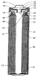
[0027] FIG. 1 illustrates one embodiment of a cell design for a lithium-
iron disulfide
electrochemical cell.
DESCRIPTION OF A PREFERRED EMBODIMENT OF THE INVENTION
[0028] Unless otherwise specified, as used herein the terms listed below
are defined and
used throughout this disclosure as follows:
[0029] ambient temperature or room temperature--between about 20 C and
about
25 C; unless otherwise stated, all examples, data and other
performance and manufacturing information were conducted at ambient
temperature;
[0030] anode--the negative electrode; more specifically, in a lithium-
iron disulfide
cell, it consists essentially of lithium or lithium-based alloy (i.e., an
alloy
containing at least 90% lithium by weight) as the primary
electrochemically active material;
[0031] capacity--the capacity delivered by a single electrode or an
entire cell during
discharge at a specified set of conditions (e.g., drain rate, temperature,
etc.); typically expressed in milliamp-hours (mAh) or milliwatt-hours
(mWh) or by the number of images taken under a digital still camera test;
[0032] cathode--the positive electrode; more specifically, in a lithium-
iron disulfide
cell, it comprises iron disulfide as the primary electrochemically active
material, along with one or more rheological, polymeric and/or conductive
additives, coated onto a metallic current collector;
Page 8A
CA 02763442 2011-11-23
WO 2010/144222
PCT/US2010/035380
[0033] cell housing ¨ the structure that physically encloses the electrode
assembly,
including all internally enclosed safety devices, inert components and
connecting materials which comprise a fully functioning battery; typically
these will include a container (formed in the shape of a cup, also referred to
as
a "can") and a closure (fitting over the opening of the container and normally
including venting and sealing mechanisms for impeding electrolyte egress and
moisture/atmospheric ingress); depending upon the context may sometimes be
used interchangeably with the terms can or container;
[0034] cylindrical cell size ¨ any cell housing having a circular-shaped
cylinder with a
height that is greater than its diameter; this definition specifically
excludes
button cells, miniature cells or experimental "hockey puck" cells;
[0035] Digital Still Camera Test (also referred to as the ANSI Digital
Still Camera Test) ¨
a camera takes two pictures (images) every minute until the battery life is
exhausted, following the testing procedure outlined in ANSI C18.3M, Part 1-
2005 published by the American National Standard for Portable Lithium
Primary Cells and Batteries¨ General and Specifications and entitled, "Battery
Specification 15LF (AA lithium iron disulfide), Digital camera test". This
test
consists of discharging a AA sized lithium iron disulfide battery at 1500 mW
for 2 seconds followed by 650 mW for 28 second, with this 30 second cycle
repeated for a total cycle of 5 minutes (10 cycles) and followed by a rest
period
(i.e., 0 mW) for 55 minutes. The entire hourly cycle 24 hours per day until a
final 1.05 voltage or less is recorded. Each 30 second cycle is intended to
represent one digital still camera image.
[0036] electrochemically active material ¨ one or more chemical compounds
that are part
of the discharge reaction of a cell and contribute to the cell discharge
capacity,
including impurities and small amounts of other moieties present;
[0037] electrode assembly interfacial area ¨ the total area of the
jellyroll electrode
assembly wherein the anode, cathode and separator are all aligned so as to
allow for an electrochemical reaction (for example, the electrode assembly
interfacial height in a cylindrically shaped jellyroll electrode assembly
would
Page 9
CA 02763442 2011-11-23
WO 2010/144222
PCT/US2010/035380
be determined by the longitudinal axis along all points where the anode,
cathode and separator are perpendicularly adjacent to one another on that
axis);
[0038] FR6 cell ¨ With reference to International Standard IEC-60086-1
published by the
International Electrotechnical Commission on after November 2000, a
cylindrical cell size lithium iron disulfide battery with a maximum external
height of about 50.5 mm and a maximum external diameter of about 14.5 mm;
[0039] FRO3 cell ¨ With reference to International Standard IEC-60086-1
published by
the International Electrotechnical Commission on after November 2000, a
cylindrical cell size lithium iron disulfide battery with a maximum external
height of about 44.5 mm and a maximum external diameter of about 10.5 mm;
100401 "jellyroll" (or "spirally wound") electrode assembly ¨ strips of
anode and cathode,
along with an appropriate polymeric separator, are combined into an assembly
by winding along their lengths or widths, e.g., around a mandrel or central
core;
[0041] loading ¨ with respect to the final dried and densified cathode mix
coated to the
foil current collector, the amount of specified material found a single facing
of
a specified area of the current collector, typically expressed as milligrams
of
total cathode mix (i.e., including pyrite, binders, conductors, additives,
etc.) on
a single side of a one square centimeter portion of the cathode collector that
is
interfacially aligned;
[0042] nominal ¨ a value, typically specified by the manufacturer, that is
representative of
what can be expected for that characteristic or property;
[0043] pyrite ¨ a mineral form of iron disulfide, typically containing at
least 95%
electrochemically active iron disulfide when used in batteries;
[0044] solids packing ¨ in a coating, but excluding the current collector,
the ratio of
volume in the coating occupied by solid particles (e.g., electrochemically
active material, binder, conductor, etc.) as compared to the total volume of
that
coating, measured after the coating has been dried and densified; typically
expressed as a percentage but also can be expressed as the inverse of the
coating's porosity (i.e., 100% minus the percent porosity of the coating);
Page 10
CA 02763442 2011-11-23
WO 2010/144222
PCT/US2010/035380
[0045] specific energy density ¨ the capacity of the electrode, cell or
battery, according to
the stated conditions (e.g., discharge at 200 mA continuous drain, total input
on an interfacial capacity, etc.) divided by the total weight of the entire
cell or
battery generally expressed in watt-hours/kilogram (Wh/kg) or milliwatt-
hours/gram (mWh/g);
100461 theoretical input capacity ¨ the capacity of the electrochemical
material(s) in a
single electrode or an entire cell based upon the theoretically available
electrochemical capacity of the material comprising the electrode/cell; may be
calculated by multiplying the weight of each active material in the electrode
by
the theoretical specific capacity of that active material, with theoretical
specific
capacity of each active material determined by: [(96,487 ampere-
seconds/mole)/(number of grams/mole of active material)] x (number of
electrons/mole of active material)/(3600 seconds/hour) x (1000 milliampere
hours/ampere-hour); Table 1 lists exemplary theoretical input capacities
calculated according to this formula:
Table 1.
Theoretical Input Capacities for Selected Materials.
Material Theoretical Input Capacity (mAh/g)
Li 3862
1672
FeS2 893.6
CFõ 864.3
CuO 673.8
CuS 560.7
Mn02 308.3
FeCuS2 292.1
[0047] theoretical interfacial input capacity ¨ the capacity of an
electrode or an entire cell
based on the overall cell discharge reaction mechanism(s) and the total amount
of active material contained within the portion of the active material mixture
adjacent to active material in the opposite electrode, assuming complete
reaction of all of the active material; if only one of the two major surfaces
of
an electrode strip is adjacent active material in the opposite electrode, only
the
Page 11
CA 02763442 2011-11-23
WO 2010/144222
PCT/US2010/035380
active material on that side of the electrode ¨ either the material on that
side of
a solid current collector sheet or that material in half the thickness of an
electrode without a solid current collector sheet ¨ is included in the
determination of interfacial capacity;
[0048] The invention will be better understood with reference to FIG. 1. In
FIG. 1, the cell 10
is one embodiment of a FR6 (AA) type cylindrical LiFeS2 battery cell, although
the invention
should have equal applicability to FRO3 (AAA) or other cylindrical cells. The
cell 10 has, in
one embodiment, a housing that includes a container in the form of can 12 with
a closed
bottom and an open top end that is closed with a cell cover 14 and a gasket
16. The can 12
has a bead or reduced diameter step near the top end to support the gasket 16
and cover 14.
The gasket 16 is compressed between the can 12 and the cover 14 to seal an
anode or negative
electrode 18, a cathode or positive electrode 20 and electrolyte within the
cell 10.
100491 The anode 18, cathode 20 and a separator 26 are spirally wound
together into an
electrode assembly. The cathode 20 has a metal current collector 22, which
extends from the
top end of the electrode assembly and is connected to the inner surface of the
cover 14 with a
contact spring 24. The anode 18 is electrically connected to the inner surface
of the can 12 by
a metal lead (or tab) 36. The lead 36 is fastened to the anode 18, extends
from the bottom of
the electrode assembly, and is folded across the bottom and up along the side
of the electrode
assembly. The lead 36 makes pressure contact with the inner surface of the
side wall of the
can 12. After the electrode assembly is wound, it can be held together before
insertion by
tooling in the manufacturing process, or the outer end of material (e.g.,
separator or polymer
film outer wrap 38) can be fastened down, by heat sealing, gluing or taping,
for example.
[0050] In one embodiment, an insulating cone 46 is located around the
peripheral portion of
the top of the electrode assembly to prevent the cathode current collector 22
from making
contact with the can 12, and contact between the bottom edge of the cathode 20
and the
bottom of the can 12 is prevented by the inward-folded extension of the
separator 26 and an
electrically insulating bottom disc 44 positioned in the bottom of the can 12.
[0051] In one embodiment, the cell 10 has a separate positive terminal
cover 40, which is held
in place by the inwardly crimped top edge of the can 12 and the gasket 16 and
has one or
Page 12
CA 02763442 2015-05-14
more vent apertures (not shown). The can 12 serves as the negative contact
terminal. An
insulating jacket, such as an adhesive label 48, can be applied to the side
wall of the can 12.
100521 In one embodiment, disposed between the peripheral flange of the
terminal cover 40
and the cell cover 14 is a positive temperature coefficient (PTC) device 42
that substantially
limits the flow of current under abusive electrical conditions. In another
embodiment, the cell
may also include a pressure relief vent. The cell cover 14 has an aperture
comprising an
inward projecting central vent well 28 with a vent hole 30 in the bottom of
the well 28. The
aperture is sealed by a vent ball 32 and a thin-walled thermoplastic bushing
34, which is
compressed between the vertical wall of the vent well 28 and the periphery of
the vent ball 32.
When the cell internal pressure exceeds a predetermined level, the vent ball
32, or both the
ball 32 and bushing 34, is forced out of the aperture to release pressurized
gases from the cell
10. In other embodiments, the pressure relief vent can be an aperture closed
by a rupture
membrane, such as disclosed in U.S. Patent Application Publication Nos.
20050244706 and
20080213651, which may be referred to for further details, or a relatively
thin area such as a coined
groove, that can tear or otherwise break, to form a vent aperture in a portion
of the cell, such
as a sealing plate or container wall.
100531 In one embodiment, the terminal portion of the electrode lead 36,
disposed between
the side of the electrode assembly and the side wall of the can, may have a
shape prior to
insertion of the electrode assembly into the can, preferably non-planar that
enhances electrical
contact with the side wall of the can and provides a spring-like force to bias
the lead against
the can side wall. During cell manufacture, the shaped terminal portion of the
lead can be
deformed, e.g., toward the side of the electrode assembly, to facilitate its
insertion into the
can, following which the terminal portion of the lead can spring partially
back toward its
initially non-planar shape, but remain at least partially compressed to apply
a force to the
inside surface of the side wall of the can, thereby making good physical and
electrical contact
with the can. Alternatively, this connection, and/or others within the cell,
may also be
maintained by way of welding.
100541 The cell container is often a metal can with a closed bottom such as
the can in FIG. 1.
The can material and thickness of the container wall will depend in part of
the active materials
and electrolyte used in the cell. A common material type is steel. For
example, the can may
Page 13
CA 02763442 2011-11-23
WO 2010/144222
PCT/US2010/035380
be made of cold rolled steel (CRS), and may be plated with nickel on at least
the outside to
protect the outside of the can from corrosion. Typically, CRS containers
according to the
invention can have a wall thickness of approximately between 7 and 10 mils for
a FR6 cell, or
6 to 9 mils for a FRO3 cell. The type of plating can be varied to provide
varying degrees of
corrosion resistance, to improve the contact resistance or to provide the
desired appearance.
The type of steel will depend in part on the manner in which the container is
formed. For
drawn cans, the steel can be a diffusion annealed, low carbon, aluminum
killed, SAE 1006 or
equivalent steel, with a grain size of ASTM 9 to 11 and equiaxed to slightly
elongated grain
shape. Other steels, such as stainless steels, can be used to meet special
needs. For example,
when the can is in electrical contact with the cathode, a stainless steel may
be used for
improved resistance to corrosion by the cathode and electrolyte.
100551 The cell cover can be metal. Nickel plated steel may be used, but a
stainless steel is
often desirable, especially when the closure and cover are in electrical
contact with the
cathode. The complexity of the cover shape will also be a factor in material
selection. The
cell cover may have a simple shape, such as a thick, flat disk, or it may have
a more complex
shape, such as the cover shown in FIG. 1. When the cover has a complex shape
like that in
FIG. 1, a type 304 soft annealed stainless steel with ASTM 8-9 grain size may
be used to
provide the desired corrosion resistance and ease of metal forming. Formed
covers may also
be plated, with nickel for example, or made from stainless steel or other
known metals and
their alloys.
100561 The terminal cover should have good resistance to corrosion by water
in the ambient
environment or other corrosives commonly encountered in battery manufacture
and use, good
electrical conductivity and, when visible on consumer batteries, an attractive
appearance.
Terminal covers are often made from nickel plated cold rolled steel or steel
that is nickel
plated after the covers are formed. Where terminals are located over pressure
relief vents, the
terminal covers generally have one or more holes to facilitate cell venting.
100571 The gasket used to perfect the seal between the can and the
closure/terminal cover
may be made from any suitable thermoplastic material that provides the desired
sealing
properties. Material selection is based in part on the electrolyte
composition. Examples of
suitable materials include polypropylene, polyphenylene sulfide, tetrafluoride-
perfluoroalkyl
Page 14
CA 02763442 2015-05-14
vinylether copolymer, polybutylene terephthalate and combinations thereof.
Preferred gasket
materials include polypropylene (e.g., PRO-FAX 6524 from Base11 Polyolefins
in
Wilmington, DE, USA) and polyphenylene sulfide (e.g., XTELTm XE3035 or XE5030
from
Chevron Phillips in The Woodlands, TX, USA). Small amounts of other polymers,
reinforcing inorganic fillers and/or organic compounds may also be added to
the base resin of
the gasket. Examples of suitable materials can be found in U.S. Patent
Publication Nos.
20080226982 and 20050079404, which may be referred to for further details.
100581 The gasket may be coated with a sealant to provide the best seal.
Ethylene propylene
diene terpolymer (EPDM) is a suitable sealant material, but other suitable
materials can be
used.
[0059] The anode comprises a strip of lithium metal, sometimes referred to
as lithium foil.
The composition of the lithium can vary, though for battery grade lithium the
purity is always
high. The lithium can be alloyed with other metals, such as aluminum, to
provide the desired
cell electrical performance or handling ease, although the amount of lithium
in any alloy
should nevertheless be maximized and alloys designed for high temperature
application (i.e.,
above the melting point of pure lithium) are not contemplated. Appropriate
battery grade
lithium-aluminum foil, containing 0.5 weight percent aluminum, is available
from Chemetall
Foote Corp., Kings Mountain, NC, USA. An anode consisting essentially of
lithium or a
lithium alloy (for example, 0.5 wt.% Al and 99+ wt.% Li) is preferred, with an
emphasis
placed on maximizing the amount of active material (i.e., lithium) in any such
alloy.
[0060] As in the cell in FIG. 1, a separate current collector (i.e., an
electrically conductive
member, such as a metal foil, on which the anode is welded or coated, or an
electrically
conductive strip running along substantial portions the length of the anode
such that the
collector would be spirally wound within the jellyroll) is not needed for the
anode, since
lithium has a high electrical conductivity. By not utilizing such a current
collector, more
space is available within the container for other components, such as active
materials. If used,
an anode current collectors could be made of copper and/or other appropriate
high
conductivity metals that are stable when exposed to the other interior
components of the cell
(e.g., electrolyte).
Page 15
CA 02763442 2011-11-23
WO 2010/144222
PCT/US2010/035380
[0061] The electrical connection is maintained between each of the
electrodes and the
opposing external battery terminals, which are proximate to or integrated with
the housing.
An electrical lead 36 can be made from a thin metal strip connecting the anode
or negative
electrode to one of the cell terminals (the can in the case of the FR6 cell
shown in FIG. 1).
This may be accomplished embedding an end of the lead within a portion of the
anode or by
simply pressing a portion such as an end of the lead onto the surface of the
lithium foil. The
lithium or lithium alloy has adhesive properties and generally at least a
slight, sufficient
pressure or contact between the lead and electrode will weld the components
together. The
negative electrode may be provided with a lead prior to winding into a
jellyroll configuration.
The lead may also be connected via appropriate welds.
[0062] The metal strip comprising the lead 36 is often made from nickel or
nickel plated steel
with sufficiently low resistance (e.g., generally less than 15mQ/cm and
preferably less than
4.5mQ/cm) in order to allow sufficient transfer of electrical current through
the lead.
Examples of suitable negative electrode lead materials include, but are not
limited to, copper,
copper alloys, for example copper alloy 7025 (a copper, nickel alloy
comprising about 3%
nickel, about 0.65% silicon, and about 0.15% magnesium, with the balance being
copper and
minor impurities); and copper alloy 110; and stainless steel. Lead materials
should be chosen
so that the composition is stable within the electrochemical cell including
the nonaqueous
electrolyte.
[0063] The cathode is in the form of a strip that comprises a current
collector and a mixture
that includes one or more electrochemically active materials, usually in
particulate form. Iron
disulfide (FeS2) is primary active material. The cathode can also contain
small amounts of
one or more additional active materials, depending on the desired cell
electrical and discharge
characteristics. The additional active cathode material may be any suitable
active cathode
material. Examples include metal oxides, Bi203, C2F, CF, (CF)n, CoS2, CuO,
CuS, FeS,
FeCuS2, Mn02, Pb2Bi205 and S. Preferably, the active material for a Li/FeS2
cell cathode
comprises at least about 95 weight percent FeS2, and most preferably FeS2 is
the sole active
cathode material. Pyrite having a purity level of at least 95 weight percent
FeS2 is available
from Washington Mills, North Grafton, MA, USA; Chemetall GmbH, Vienna,
Austria; and
Kyanite Mining Corp., Dillwyn, VA, USA. Note that the discussion of "purity"
of FeS2
Page 16
CA 02763442 2015-05-14
acknowledges that pyrite is a specific and preferred mineral form of FeS2.
however, pyrite
often times has small levels of impurities (typically silicon oxides) and,
because only the FeS2
is electrochemically active in pyrite, references to percent purity of FeS2
are made with
respect to the total amount of pyrite, usually on a weight percentage basis.
Thus, pyrite and
FeS2 may not be synonymous when read in proper context. A more comprehensive
description of the cathode, its formulation and a manner of manufacturing the
cathode is
provided below.
100641 The cathode mixture is coated onto one or both sides of a thin metal
strip which serves
as the cathode current collector. Aluminum is a commonly used material,
although titanium,
copper, steel, other metallic foils and alloys thereof are also possible. The
current collector
may extend beyond the portion of the cathode containing the cathode mixture.
This extending
portion of the current collector can provide a convenient area for making
contact with the
electrical lead connected to the positive terminal, preferably via a spring or
pressure contact
that obviates the need for a lead and/or welded contacts. It is desirable to
keep the volume of
the extending portion of the current collector to a minimum to make as much of
the internal
volume of the cell available for active materials and electrolyte. Examples of
typical coating
configurations for the cathode can be found in U.S. Patent Publication No.
20080026293,
which may be referred to for further details.
100651 The cathode is electrically connected to the positive terminal of
the cell. This may be
accomplished with an electrical lead, often in the form of a thin metal strip
or a spring, as
shown in FIG. 1, although welded connections are also possible. If used, this
lead can be
made from nickel plated stainless steel or other appropriate materials. In the
event an optional
current limiting device, such as a standard FTC, is utilized as a safety
mechanism to prevent
runaway discharge/heating of the cell, a suitable PTC is sold by Tyco
Electronics in Menlo
Park, CA, USA. A typical, standard FTC device generally comprises a resistance
of
approximately 36 inSI/cm. Other alternatives, including lower resistance
devices of
approximately 18 me/cm, are also available. Alternative current limiting
devices can be
found in U.S. Publication Nos. 20070275298 and 20080254343, which may be
referred to
for further details.
Page 17
CA 02763442 2015-11-30
100661 The
separator is a thin microporous membrane that is ion-permeable and
electrically
nonconductive. It is capable of holding at least some electrolyte within the
pores of the
separator. The separator is disposed between adjacent surfaces of the anode
and cathode to
electrically insulate the electrodes from each other. Portions of the
separator may also
insulate other components in electrical contact with the cell terminals to
prevent internal short
circuits. Edges of the separator often extend beyond the edges of at least one
electrode to
insure that the anode and cathode do not make electrical contact even if they
are not perfectly
aligned with each other. However, it is desirable to minimize the amount of
separator
extending beyond the electrodes.
100671 To provide
good high power discharge performance, it is desirable that the separator
have the characteristics (pores with a smallest dimension of at least about
0.005 i.tm and a
largest dimension of no more than about 5 pm across, a porosity in the range
of about 30 to 70
percent, an area specific resistance of from 2 to 15 ohm-em2 and a tortuosity
less than 2.5)
disclosed in U.S. Patent No.5,290,414, issued March 1, 1994, which may be
referred to
for details. Other desirable separator properties are described in U.S. Patent
Publication
No. 20080076022, which may be referred to for further details.
100681 Separators
are otten made of polypropylene, polyethylene or both. The separator can
be a single layer of biaxially oriented microporous membrane, or two or more
layers can be
laminated together to provide the desired tensile strengths in orthogonal
directions. A single
layer is preferred to minimize the cost. The membrane should have a thickness
between 16
and 25 microns, depending upon the cathode formulation and constraints on
container
strength disclosed herein. Suitable separators are available from Tonen
Chemical Corp.,
available from EXXON Mobile Chemical Co., Macedonia, NY, USA and Entek
Membranes
in Lebanon, OR, USA.
100691 A nonaqueous electrolyte, containing water only in very small
quantities as a
contaminant (e.g., no more than about 500 parts per million by weight,
depending on the
electrolyte salt being used), is used in the battery cell of the invention.
The electrolyte
contains one or more lithium-based electrolyte salts dissociated in one or
more organic
solvents. Suitable salts include one or more of the following: lithium
bromide, lithium
perchlorate, lithium hexafluorophosphate, potassium hexafluorophosphate,
lithium
Page 18
CA 02763442 2011-11-23
WO 2010/144222
PCT/US2010/035380
hexafluoroarsenate, lithium trifluoromethanesulfonate and lithium iodide,
although the salt
preferably includes F (e.g., by dissociation of LiI in the solvent blend).
Suitable organic
solvents include one or more of the following: methyl formate, y-
butyrolactone, sulfolane,
acetonitrile, 3,5-dimethylisoxazole, n,n-dimethyl formamide and ethers,
although at least 50
volume percent of the total solvents must be ether because its low viscosity
and wetting
capability appear to positively influence the thicker electrode constructions
described below.
Preferred ethers can be acyclic (e.g., 1,2-dimethoxyethane, 1,2-
diethoxyethane,
di(methoxyethyl)ether, triglyme, tetraglyme and diethyl ether) and/or cyclic
(e.g., 1,3-
dioxolane, tetrahydrofuran, 2-methyl tetrahydrofuran and 3-methy1-2-
oxazolidinone). 1,3-
dioxolane and 1,2-dimethoxyethane are the preferred solvents, while lithium
iodide is the
preferred salt, although it may be used in combination with lithium triflate,
lithium imide or
lithium perchlorate. Additives that result in the creation ofF dissociated in
the solvent blend
may also be used.
[0070] The anode, cathode and separator strips are combined together in an
electrode
assembly. The electrode assembly may be a spirally wound design, such as that
shown in
FIG. 1, made by winding alternating strips of cathode, separator, anode and
separator around
a mandrel, which is extracted from the electrode assembly when winding is
complete. At
least one layer of separator and/or at least one layer of electrically
insulating film (e.g.,
polypropylene) is generally wrapped around the outside of the electrode
assembly. This
serves a number of purposes: it helps hold the assembly together and may be
used to adjust
the width or diameter of the assembly to the desired dimension. The outermost
end of the
separator or other outer film layer may be held down with a piece of adhesive
tape or by heat
sealing. The anode can be the outermost electrode, as shown in FIG. 1, or the
cathode can be
the outermost electrode. Either electrode can be in electrical contact with
the cell container,
but internal short circuits between the outmost electrode and the side wall of
the container can
be avoided by matching the polarity of the outermost wind of the electrode
assembly to that of
the can.
[0071] The cell can be closed and sealed using any suitable process. Such
processes may
include, but are not limited to, crimping, redrawing, colleting and
combinations thereof. For
example, for the cell in FIG. 1, a bead is formed in the can after the
electrodes and insulator
Page 19
CA 02763442 2015-05-14
cone are inserted, and the gasket and cover assembly (including the cell
cover, contact spring
and vent bushing) are placed in the open end of the can. The cell is supported
at the bead
while the gasket and cover assembly are pushed downward against the bead. The
diameter of
the top of the can above the bead is reduced with a segmented collet to hold
the gasket and
cover assembly in place in the cell. After electrolyte is dispensed into the
cell through the
apertures in the vent bushing and cover, a vent ball is inserted into the
bushing to seal the
aperture in the cell cover. A PTC device and a terminal cover are placed onto
the cell over
the cell cover, and the top edge of the can is bent inward with a crimping die
to hold and
retain the gasket, cover assembly, PTC device and terminal cover and complete
the sealing of
the open end of the can by the gasket.
100721 With respect to the cathode, the cathode is coated onto a metallic
foil current collector,
typically an aluminum foil with a thickness between about 16 and 20 lint. The
cathode is
formed as a mixture which contains a number of materials that must be
carefully selected to
balance the processability, conductivity and overall efficiency of the
coating. These
components are mixed into a slurry in the presence of a solvent, such as
trichloroethylene, and
then coated onto the current collector. The resulting coating is preferably
dried and densified
after coating, and it consists primarily of iron disulfide (and its
impurities); a binder to hold
the particulate materials together and adhere the mixture to the current
collector; one or more
conductive materials such as metal, graphite and carbon black powders to
provide improved
electrical conductivity to the mixture; and various processing or rheological
aids, such as
fumed silica and/or an overbased calcium sulfonate complex. A preferred
cathode
formulation is disclosed in U.S. Patent Publication 20090104520, which may be
referred to for further
details. Additionally, it has been determined that lithium-irondisulfide
batteries intended
for high rate applications inure benefits by providing an excess of
theoretical interfacial input
capacity in the cathode as compared to the theoretical interfacial input
capacity of the anode
associated therewith, as described in U.S. Patent No. 7,157,185 which may be
referred to for
further details. Thus, in one embodiment, cells of the invention have an
interfacial anode to
cathode input ratio of less than 1.00.
100731 The following are representative materials utilized in the preferred
cathode
formulation. between 94 wt.% to 99 wt.% pyrite, 0.1-3.0 wt.% conductor, about
0.1-3.0 wt.%
Page 20
CA 02763442 2015-05-14
binder, and about 0-1.0 wt.% processing aids. It is more desirable to have a
cathode mixture
with about 95-98 wt.% pyrite, about 0.5-2.0 wt.% conductor, about 0.5-2.0 wt.%
binder, and
about 0.1-0.5 wt.% processing aids. It is even more desirable to have a
cathode mixture with
about 96-97 wt.% pyrite, about 1.0-2.0 wt.% conductor, about 1.0-1.5 wt.%
binder, and about
0.3-0.5 wt.% processing aids. The conductor may comprise PureBlackTm (carbon
black) 205-
110 from Superior Graphite Chicago, IL and/or MX15 from Timcal Westlake, OH.
The
binder/processing aids may comprise a polymeric binder comprising a styrene-
ethylene/butylenes-styrene (SEBS) block copolymer, such as g1651 from Kraton
Polymers
Houston, TX, and EFKA 6950 overbased calcium sulfonate complex previously
available
from Ciba, Heerenveen, Netherlands or AEROSIL 200 fumed silica from Evonik
Industries
AG, Essen, Germany.
100741 It is also desirable to use cathode materials with small particle
sizes to minimize the
risk of puncturing the separator. For example, FeS2 can be sieved, at least
through a 230
mesh (62 am) screen or smaller. More preferably, the FeS2 may be media milled
to have an
average d50 particle size than 10 p.m or less or processed, as described in
U.S. Patent
Publication No. 20050233214, which may be referred to for further details.
100751 The cathode mixture is applied to the foil collector using any
number of suitable
processes, such as three roll reverse, comma coating or slot die coating.
After or concurrent
with drying to remove any unwanted solvents, the resulting cathode strip is
densified via
calendering or the like to further compact the entire positive electrode. In
light of the fact that
this strip will then be spirally wound with separator and a similarly (but not
necessarily
identically) sized anode strip to form a jellyroll electrode assembly, this
densification
maximizes loading of electrochemical material in the jellyroll electrode
assembly. Particular
advantages have been demonstrated in one embodiment of the invention when the
cathode
loading exceeds at least 28 mg of mix/cm2 on one facing (i.e., one side) of
the current
collector, more preferably exceeding 30 mg/cm2 and most preferably exceeding
32 mg/cm2,
as illustrated in the examples below.
[0076] However, the cathode cannot be over-densified as some internal
cathode voids are
needed to allow for expansion of the iron disulfide during discharge and
wetting of the iron
disulfide by the organic electrolyte. More practically, there are also
operational limits as to
Page 21
CA 02763442 2015-11-30
the amount of force that can be applied to compact the coatings to high
densities, and the
stress on the current collector created by such forces can result in unwanted
stretching and/or
actual de-lamination of the coating. Therefore, it is preferable that the
solids packing
percentage in the final densified cathode must be sufficient to allow for the
electrochemical
reaction to proceed. Preferably, the final solids packing must be between
about 58 vol. %
and 70 vol. %.
[00771 Improvements to the electrochemical cell can be measured based on
the
electrochemical cell performance under a variety of different high rate tests.
Ultimately, the
best performing, prior art FR6 cell known to the inventor had a DSC
performance of about
330 minutes. This prior art cell also had approximately 22 mg of cathode mix,
including 92
wt.% of pyrite, per cm2 on a single side of the two-sided cathode current
collector and 220
cm2 of total interfacial surface area between the electrodes, resulting in
approximately 18
mWh/cm2 of interfacial surface area for the DSC test. Other known FR6 cells
typically varied
between about 18 mg to 25 mg of mix/cm2 of a single side of the cathode (based
on between
80 to 88 wt.% pyrite) and 200 to 220 cm2 of interfacial surface area; however,
these cells did
markedly worse on the DSC test, typically yielding no better than about 260 to
285 minutes
and about 15 to 17 mWh/cm2. In extreme cases, cells were observed to have
loading 28 mg
or more of mix/cm2, but these cells performed the worst of all known prior art
on the DSC test
(e.g., usually less than 250 minutes, sometimes even providing no service),
possibly explained
by their choice of electrolyte, solids packing and/or relatively low weight
percentage of pyrite.
In every instance, all known prior art FR6 cells had an anode consisting of at
least 99.5 wt.%
lithium with a thickness less than about 165 microns and a cathode coating
having less than
93 wt.% of pyrite. Similarly, all of these cells show less than 20% decrease
in the R 10
resistance during the DSC at two thirds (i.e., 66%) depth of discharge.
Notably, two thirds
depth of discharge is within the range where the maximum decrease in this
resistance is
observed.
100781 This data reflects the belief in the art is that the interfacial
surface area between the
electrodes should be maximized to optimize the cell's performance on high rate
applications
such as the DSC test. In a fixed space, such as an FR6 can, the thickness of
the electrodes
impacts the amount of interfacial surface area. Thicker electrodes will result
in fewer winds
Page 22
CA 02763442 2011-11-23
WO 2010/144222
PCT/US2010/035380
within the jellyroll and, by extension, an expectation of reduced interfacial
surface area and
reduced DSC performance. Additional processing and manufacturing difficulties
may also
occur; for example, the cathode mix formulation, coating and densification
operations will all
be impacted as the cathode thickness increases, as will the jellyroll winding
when the
electrode thickness changes. Consequently, it had been considered desirable to
maintain a
jellyroll interfacial area of about 200 to 220 cm2 in an FR6 cell, which
corresponds to an
anode thickness between 140 and 165 microns, a separator thickness between 16
to 25
microns and a cathode thickness between 180 and 220 microns (inclusive of the
current
collector).
100791 The inventor has now discovered, quite unexpectedly, that increasing
the thickness of
the anode, in combination with increasing the weight percent pyrite in the mix
and/or the
loading of mix on the current collector while maintaining the coating solids
packing within a
specific range, yields significantly improved high rate performance with
little to no impact on
the other performance characteristics of the cell, notwithstanding the fact
that these changes
necessarily reduces the overall interfacial surface area in the electrode
assembly. In
particular, an interfacial surface area of less than 200 cm2 is contemplated,
which corresponds
to an anode of thickness of at least 175 microns in an FR6 cell. The final
solids packing of
the cathode must be between 58% to 70%, while the cathode coating have at
least 24 mg, and
more preferably in excess of 28 mg, of mix per single side of current
collector and/or at least
91 wt.% of pyrite, and more preferably in excess of 93 wt.%. In each instance,
an electrolyte
having at least 50% ethers and substantially no carbonates is needed.
Preferably, the
electrolyte solution will have 1- as one of its dissociated electrolytic salts
or as an electrolyte
additive. F can be formed through the use of the lithium-based salt lithium
iodide being
dissolved in a solvent blend preferably having at least 90 vol.% of one or
more ethers (based
on the total volume of the solvents). However, carbonates cannot normally be
used in the
blend. While not intending to be bound by any specific theory, it is believed
carbonates
possess relatively high viscosity, wetting properties to interact beneficially
with the preferred
cathode described above.
[0080] The amount of FeS2 in the cathode coating can either be determined
by analyzing the
mixture prior to fabrication of the battery or by determining the iron content
post-formulation
Page 23
CA 02763442 2011-11-23
WO 2010/144222
PCT/US2010/035380
and correlating the detected level of iron to the weight percentage of pyrite
in the cathode.
The method of testing for iron content post-fabrication can be conducted by
dissolving a
known amount (in terms of mass and volume/area) of cathode in acid, then
testing for the total
amount of iron in that dissolved sample using common quantitative analytical
techniques,
such as inductively coupled plasma atomic emission spectroscopy or atomic
absorption
spectroscopy. Testing of known coated cathode formulations according to this
method have
verified that the total amount of iron is representative of FeS2 in the cell
(particularly to the
extent that is desirable to maximize the purity of FeS2 in the cathode
coating). It may also be
possible to determine cathode density using a pycnometer, although certain
binders may
experience volumetric changes when exposed to the internal environment of a
lithium-iron
disulfide cell such that the density established by such methods may need to
be adjusted
further in order to arrive at the cathode dry mix density.
[0081] Notably, testing for the quantity of aluminum in the sample will
allow for calculation
of the thickness of the current collector (when the collector is aluminum) in
a similar manner
(e.g., ICP-AES or AA spectroscopy). Other similar analytical techniques may be
employed to
test for binders, processing aids and the like, depending upon the atomic
and/or molecular
composition of those components, and analysis of the anode and/or separator is
possible using
similar analytical and quantitative/qualitative techniques.
[0082] To the extent that the weight per unit area of the cathode is to be
determined from a
post-fabrication, the cathode should be rinsed to remove any electrolyte
remnants and
thoroughly dried to insure solvent does not contribute to the measure weight.
The weight
contribution from the current collector may then be subtracted from this
measurement through
the appropriate empirical analysis of the collector described above.
[0083] R10 resistance, as used throughout this specification, is a specific
cell resistance
measurement technique using a current interrupt method. The R10 resistance
primarily
reflects the ohmic resistance of the cell (i.e., the resistance to electrical
current flow that
follows Ohm's law).
100841 RIO resistance can be measured during any service test, although as
used herein, the
R10 resistance is measured during the Digital Still Camera Test. Specifically,
a double pulse
technique is employed with the measured voltage and the current data being
first observed at
Page 24
CA 02763442 2011-11-23
WO 2010/144222
PCT/US2010/035380
the 10th high power pulse step in each cycle of the DSC test (e.g., the 10th
1500mW pulse of
an FR6 DSC Test) and also at the 100 millisecond interval of the corresponding
low power
step of that same cycle (e.g., the 650W pulse). Similar measurements are
recorded on the 10th
pulse of every cycle for the entire DSC Test. In turn, the first measurement
(i.e., taken when
approximately 5 minutes have elapsed in the test) can be compared to another
measurement at
predetermined point during the discharge regime. As used throughout the
specification, the
R10 resistance of the first cycle will compared to a second measurement at
approximately the
two thirds depth of discharge point during the DSC Test.
[0085] The precise calculation for the two comparative measurements (i.e.,
the first interval
being the 10th pulse of the first cycle and the second interval being the 10th
pulse of the cycle
closest to the two thirds depth of discharge point) is as follows, with Vhp
and Ihp being the
voltage and current of the high power step at the end of the 10th pulse of the
discharge cycle
(e.g., 5 minutes or 66% depth of discharge) and V1p and lip being the voltage
and current 100
milliseconds into the low power pulse immediately following the aforementioned
high power
step, respectively.
Vhp Vlp (t=100 ms)
[0086] R101nterval ¨ , \
'hp (t=100 ms/
[0087] To the extent that data may not be recorded precisely at the two
thirds depth of
discharge point, it is possible to interpolate between the two closest data
points in order to
accurately and effectively determine the necessary value. It should also be
apparent that the
DSC Test must be run to its completion in order to definitively establish the
comparison
points inherent to the R10 resistance measurements contemplated herein. Also,
R10
resistance for FRO3 cells (or any other size) can be determined accordingly
using the same
method for FR6, but with the high and low power pulses adjusted for AAA size
according to
ANSI CI 8.3M, Part 1 2005 standard (or the appropriate standard).
[0088] The entirety of the above description is particularly relevant to
FR6 and FRO3 cells.
However, the invention might also be adapted to other cylindrical cell sizes
where the
sidewall height exceeds the diameter of the container, cells with other
cathode coating
schemes and/or seal and/or pressure relief vent designs.
Page 25
CA 02763442 2011-11-23
WO 2010/144222
PCT/US2010/035380
[0089] Features of the invention and its advantages will be further
appreciated by those
practicing the invention. Furthermore, certain embodiments of the components
and the
performance of the cell assembled as described will be realized. It will be
understood by
those who practice the invention and those skilled in the art that various
modifications and
improvements may be made to the invention without departing from the teachings
of the
disclosed concepts. The scope of protection afforded is to be determined by
the claims and by
the breadth of interpretation allowed by law.
[0090] The invention will now be described with reference to the following
non-limiting
examples.
EXAMPLE
[0091] A series of FR6 cells were constructed as shown in Tables la and lb
below. For Lots
1-8, an identical cell housing, electrolyte solution and separator thickness
were used, such that
only the thickness of the lithium, solids packing and loading of the cathode
and separator
manufacturer were appreciably altered. Lots 1 and 3 represent comparative
examples created
by the inventor (i.e., these cells do not represent prior art examples), while
lot 2 represents the
best performing, prior art FR6 cell known to the inventor (also referenced
above). Lots 4, 5,
6, 7 and 8 are various embodiments of the invention. In this manner, direct
comparisons can
be made regarding the effects of anode thickness and cathode formulation for
Lots 1-8.
[0092] Additional comparative examples are shown, Lots A, B and C. Lots A-C
are other
FR6 cells from the prior art. While many of the components, including the cell
housing
materials and anodes, for Lots A-C are believed to be substantially similar to
those used in
Lots 1-8, Lots A-C have different/unknown electrolyte formulations (possibly
based on
lithium trifiate, lithium imide and/or lithium perchlorate salts dissolved in
all ether solvents),
thicker separators and different cathode formulations. In this manner, further
comparisons on
these points can be made between Lots 4-8 and A and B.
Page 26
CA 02763442 2011-11-23
WO 2010/144222 PCT/US2010/035380
Table la
Lot 1 2 3 A B C
-
Pyrite wt. /0 of total mix 96.5 92 85.7 -to -80 to -85
to
88 88
Cathode loading -20 to -22 to -22
to
14.6 21.8 31.9
(mg mix/cm2) 22 24 24
i-5
Cathode solids packing 0/0 70 64 70 -63 to -60 to 8 to
67 69 64
Li thickness (pm) 102 152 203 -150 -145 -155
Lithium width (cm) 3.899 3.899 3.899 -3.900 -4.000 -
3.990
Interfacial area (cm2) 327 219 175 -215 -210 -201
Electrolyte LiI (molality) 0.75 0.75 0.75 N/A N/A N/A
Separator thickness (pm) 20 20 20 25 25 25
Table lb __________________________________
Lot 4 5 6 7 8
Pyrite wt.% of total mix 96.4 96.4 91 _ 96.5 96.5
Cathode loading
28.3 28.3 30.0 33.6 33.6
(mg mix/cm2)
Cathode solids packing % 58 70 64 60 60
Li thickness (pm) 203 203 203 229 254
Lithium width (cm) 3.899 3.899 3.899 3.899 3.899
Interfacial area (cm2) 182 195 178 157 145
Interfacial anode to
0.90 0.90 0.90 0.85 0.85
cathode input ratio
Electrolyte LiI (molality) 0.75 0.75 0.75 0.75 0.75
Separator thickness (pm) 20 20 20 20 20
100931 All cells were constructed with a ratio of theoretical interfacial
input capacity of the
anode to theoretical interfacial input ratio of the cathode that is less than
1.00, thereby
allowing for fair comparisons on high rate tests. In turn, these cells were
tested on the Digital
Still Camera test while their R10 resistance was monitored. Results for these
tests are shown
in Tables 2a and 2b.
Table 2a
Lot 1 2 3 A B C
DSC performance
328 333 303 275 264 285
(minutes)
Energy on DSC test (mWh) 3866 3922 3565 3239 3109
3356
Energy per unit interfacial
area on DSC test 11.8 17.9 20.4 15.1 14.8
16.7
(mWh/cm2)
R101st (n) 1 0.102 0.103 0.097 0.066 0.146
0.118
Page 27
CA 02763442 2011-11-23
WO 2010/144222 PCT/US2010/035380
Lot 1 2 3 ¨ A B C
DSC service at 2/3 (min) 219 222 202 183 176 203
R102nd (Q) at 2/3 DOD on
0.093 0.091 0.082 0.055 0.136
0.110
DSC
% of decrease 9% 12% 16% 17% 7% 7%
Table 2b
Lot 4 5 6 7 8 __
DSC performance
374 389 347 363 340
(minutes)
Energy (mWh) on DSC test 4405 4581 4084 4275 3998
Energy per unit interfacial
area on DSC test 24.2 23.6 22.9 27.2 27.7
(mWh/cm A 2) __
R101st (Q) 0.113 0.114 0.109 0.156 0.164
DSC service at 2/3 (min) 249 259 231 242 226
R102,-,d (Q) at 2/3 DOD on
0.076 0.073 0.081 0.083 0.081
DSC
% of decrease 33% 36% 26% 470/0 50%
[0094] With respect to the foregoing results, it should be noted that high
interfacial surface
area design in Lot 1 is still inferior to Lots 4-8 (in terms of DSC test
results), mostly like
because of Lot 1 does not utilize the requisite cathode loading. Similarly,
although Lot 3
possesses a relatively high cathode loading and low interfacial surface area,
Lot 3 is inferior
to Lots 4-8 due to its cathode mix failing to have enough weight percent of
pyrite. In place of
pyrite in Lot 3, graphite conductor attributed approximately 12 wt.% of this
particular
formulation; however, notwithstanding the expectation of improved cathode
efficiency
expected from extra conductor, Lot 3 failed to approach the high rate results
of Lots 4-8. In
this manner, it can be seen that only cells possessing the appropriate
combination of lithium
thickness, cathode final solids packing, weight percent pyrite in the cathode
mix and cathode
loading achieve improved high rate performance characteristics.
[0095] In view of the foregoing, an electrochemical cell comprising any
combination of the
following features is contemplated:
= an R6 sized container having a height no greater than about 50.5 mm and a
diameter no greater than about 14.5 mm;
Page 28
CA 02763442 2011-11-23
WO 2010/144222
PCT/US2010/035380
= a jellyroll electrode assembly having less than 200 cm2 of interfacial
area between
an anode consisting essentially of lithium or lithium-based alloy and a
cathode
comprising a mix coated onto a metallic foil current collector, wherein the
mix has
at least 91 wt.% pyrite and a final solids packing between 58% to 70%;
= an electrolyte consisting essentially of one or more electrolytic salts
dissociated in
one or more solvents comprising at least 50 vol.% of one or more ethers based
on
total volume of the solvents, said one or more solvents not including any
carbonate-based solvents;
= wherein the cell has an energy per unit of interfacial area in excess of
21 mWh/cm2
on the Digital Still Camera Test;
= wherein energy per unit of interfacial area in excess of 23 mWh/cm2 on
the
Digitial Still Camera Test;
= wherein the cell has an energy per unit of interfacial area in excess of
27 mWh/cm2
on the Digital Still Camera Test;
= wherein the interfacial area is less than 185 cm2;
= wherein the interfacial area is less than 175 cm2;
= wherein the mix has at least 93 wt.% of pyrite;
= wherein the mix has at least 96 wt.% of pyrite;
= wherein the one or more solvents comprise greater than 90 vol.% of one or
more
ethers; and/or
= wherein the one or more electrolytic salt, when dissociated in the one or
more
solvents, includes F.
100961
Additionally, an electrochemical cell comprising any combination of the
following
features is contemplated:
= a container;
= a jellyroll electrode assembly having a separator with a thickness of 25
microns or
less disposed between an anode consisting essentially of lithium or lithium-
based
alloy with a thickness of at least 200 microns and a cathode comprising a mix
coated onto a metallic foil current collector, said mix comprising a final
solids
Page 29
CA 02763442 2011-11-23
WO 2010/144222
PCT/US2010/035380
packing is between 58% to 70% and having a loading of at least 28 mg of
mix/cm2
on each side of the two sides of the current collector (i.e., 56 mg when both
sides
of a two sided collector are considered);
= an electrolyte including at least one lithium-based salt and one or more
solvents
having at least 50 vol.% of one or more ethers, based on total volume of the
solvents;
= wherein the cell experiences a comparative drop of R10 resistance in
excess of
20% at about 66% depth of discharge during the Digital Still Camera Test;
= wherein the drop of R10 resistance is in excess of 30%;
= wherein the drop of R10 resistance is in excess of 45%;
= wherein the thickness of lithium is at least 225 microns;
= wherein the thickness of the lithium is at least 250 microns;
= wherein the thickness of the separator is greater than 16 microns;
= wherein the mix has a loading of at least 30 mg/cm2;
= wherein the one or more solvents have greater than 90 vol.% of one or
more
ethers;
= wherein the one or more solvents do not contain any carbonates; and/or
= wherein the electrolyte further comprises 1- dissociated in the one or
more solvents.
100971
Finally, an electrochemical cell comprising any combination of the following
features
is contemplated:
= a container;
= a jellyroll electrode assembly having: i) a separator with a thickness
between 16
and 25 microns, ii) an anode consisting essentially of lithium or lithium-
based
alloy with a thickness of at least 175 microns, and iii) a cathode comprising
a mix
with at least 91 wt.% pyrite coated onto a metallic foil current collector,
said mix
having a final solids packing between 58% to 70% and a loading of at least 24
mg
of mix/cm2 on each side of the two sides of the current collector;
Page 30
CA 02763442 2011-11-23
WO 2010/144222
PCT/US2010/035380
= an electrolyte comprising one lithium-based salt and one or more
solvents, said
one or more solvents consisting of at least 50 vol.% of one or more ethers
based on
total volume of the solvents;
= wherein the jellyroll electrode assembly has a ratio of theoretical
interfacial input
capacity of the anode to theoretical interfacial input ratio of the cathode
that is less
than 1.00;
= wherein the jellyroll electrode assembly has a ratio that is less than or
equal to
0.90;
= wherein the jellyroll electrode assembly has a ratio that is less than or
equal to
0.85;
= wherein the thickness of the anode is at least 200 microns, the mix
comprises at
least 94 wt.% pyrite and the mix has a loading at least 28 mg/cm2;
= wherein the thickness of the anode is at least 225 microns, the mix
comprises at
least 96 wt.% pyrite and the mix has a loading of at least 30 mg/cm2;
= wherein the cell has at least one during the Digital Still Camera test
selected from
the group consisting of: i) a comparative drop of R10 resistance in excess of
20%
at about 66% depth of discharge, and ii) an energy per unit of interfacial
area in
excess of 21 mWh/cm2;
= wherein the cell has at least one during the Digital Still Camera test
selected from
the group consisting of: i) a comparative drop of R10 resistance in excess of
30%
at about 66% depth of discharge, and ii) an energy per unit of interfacial
area in
excess of 23 mWh/cm2;
= wherein the one or more solvents do not contain any carbonates and
consist of
greater than 90 vol.% of one or more ethers; and/or
= wherein the electrolyte further comprises I- dissociated in the one or
more solvents.
Page 31