Note: Descriptions are shown in the official language in which they were submitted.
CA 02763512 2015-05-14
REMOVAL OF MOISTURE FROM PROCESS GAS
Background
[002] When high concentrations of an acidic component, such as 002, H2S, HF,
HCI, H2SO4,
or H3NO3, are present in a gas, the gas is generally referred to as an "acid
gas." The acidic
component of acid gas will generally cause the pH of liquids contained in the
gas, such as
water, to fall to between about 3 and 5, for example. In gas compression
technology, liquids
(e.g., water) with a pH below 4 have been shown to cause Sulfide Stress
Cracking (SSC), a
form of corrosion, in the metal or alloy components of the gas compression
equipment.
Typically, corrosion is the most severe during the initial stages of
compression, or after an
inter-cooler, where the gas temperature is lowered and condensate is formed,
but is not
completely removed from the gas.
[003] Gases are often cooled before compression and between stages of
compression to
improve the efficiency of compression, and to keep the gas temperature low
enough to be
handled with common materials of construction. Process gases are often cooled
by water or
air-cooled heat exchangers to lower their temperature to near ambient, or at
least below about
120 F. If the gas has water vapor in it, the cooling of the gas below the dew
point results in the
condensation of water from the gas. The dew point is the temperature and
pressure at which
water vapor condenses from the gas phase to the liquid phase.
[004] Conventional compressor systems may include one or more dehydration
systems
configured to remove moisture from a process gas before it enters a
compressor. A
dehydration system may include a glycol system that is capable of removing all
free moisture
and all but about 1Oppm of water (or less). However, such glycol systems may
be expensive,
because the component parts must be made of highly expensive alloys that can
tolerate
corrosive conditions.
[005] More commonly, a conventional compressor system may include an cooling
unit
configured to cool a process gas to produce condensate, and then pass the
cooled gas
containing the condensate to a demister configured to remove condensate from
the cooled
process gas. However, demisters are known to be incapable of removing all
condensate from
a process gas. The extent to which condensate is removed varies with the
design of the heat
exchanger and the demister. Thus, a cooling unit/demister configuration may,
at best, leave
the process gas saturated with water, and depending on the efficiency of the
demister, a
cooling unit/demister configuration could even leave condensate in the process
gas.
[006] Thus, there is a need for a more effective and less expensive system
and/or method for
reducing corrosion in turbomachines by reducing or eliminating liquid water
from process gas.
1
CA 02763512 2011-11-24
WO 2010/138403 PCT/US2010/035721
Summary
[007] In a broad embodiment of the present disclosure, an exemplary method is
provided for
operating a compressor system. The method may include providing a process gas
containing water
vapor to a cooling unit. The cooling unit may be configured to cool the water
vapor to a temperature
below the dew point. Cooling the water vapor to a temperature below the dew
point causes water
vapor present in the process gas to form a condensate. At least a portion of
the condensate is then
removed. The process gas, along with any remaining condensate, is then
directed to a heat
exchanger configured to heat the process gas and any remaining condensate to a
temperature
above the dew point. Heating the process gas and any remaining condensate to
the temperature
above the dew point causes any remaining condensate to evaporate, thus
creating a dry and non-
corrosive gas to be supplied to the compressors.
[008] Exemplary embodiments of the disclosure may further provide an exemplary
method for
operating a compressor system that may include providing a process gas having
water vapor to a
moisture removal unit located at the front of the turbomachine upon starting
the turbomachine. The
moisture removal unit may include a heating unit configured to heat the
process gas to a
temperature at which the condensate evaporates. The method may also include
providing a dry
gas to the turbomachine upon shutting down the turbomachine, and providing an
increasing amount
of heated water to the heating unit as the turbomachine shuts down.
[009] Exemplary embodiments of the disclosure may further provide an exemplary
moisture
removal unit for a compressor system, which may include a cooling unit and a
heating unit. The
cooling unit may include a means for cooling a process gas containing water
vapor to a first
temperature, wherein the water vapor forms a condensate at the first
temperature, and the means
for cooling the process gas produces residual heat when cooling the process
gas. The cooling unit
may also include a means for removing at least a portion of the condensate
from the process gas,
wherein any condensate not removed is a remaining condensate. The heating unit
may include a
means for using the residual heat to heat the remaining condensate to a second
temperature,
wherein the remaining condensate in the process gas evaporates at the second
temperature.
[0010] Exemplary embodiments of the disclosure may further provide an
exemplary method for
operating a turbomachine, wherein the method may include providing, a process
gas having water
vapor to a moisture removal unit located at the front of the turbomachine upon
starting the
turbomachine. The moisture removal unit may include a cooling unit and a
heating unit. The
cooling unit may include a means for cooling a process gas comprising water
vapor to a first
temperature, wherein the water vapor forms a condensate at the first
temperature. The means for
cooling the process gas may produce residual heat when cooling the process
gas. The cooling unit
may also include means for removing at least a portion of the condensate from
the process gas,
wherein any condensate not removed is a remaining condensate. The heating unit
may be
2
CA 02763512 2011-11-24
WO 2010/138403 PCT/US2010/035721
configured to heat the process gas to a temperature at which the remaining
condensate evaporates.
The¨rifethod may further include providing a dry gas to the tiirtiolfiathiW0p-
on-shutting-down-the-----
turbomachine, and providing an increasing amount of heated water to the
heating unit as the
turbomachine shuts down.
[0011] Exemplary embodiments of the disclosure may further provide an
exemplary method of
operating a compressor system. The method may include providing heated water
to one or more
compressors of the compressor system upon starting the compressor system,
providing a dry gas
into the compressor system upon shutting down the compressor system, and
providing heated
water to one or more cooling units of the compressor system upon shutting down
the compressor
system.
Brief Description of the Drawings
[0012] The present disclosure is best understood from the following detailed
description when read
with the accompanying figures. it is emphasized that, in accordance with the
standard practice in
the industry, various features are not drawn to scale. In fact, the dimensions
of the various features
may be arbitrarily increased or reduced for clarity of discussion.
[0013] Figure 1 illustrates a schematic view of an exemplary compressor system
according to one
or more aspects of the present disclosure.
[0014] Figure 2 illustrates a flow chart of an exemplary method for reducing
corrosion in
compressors according to one or more aspects of the present disclosure.
[0016] Figure 3 illustrates a schematic view of an exemplary compressor
according to one or more
aspects of the present disclosure.
[0016] Figure 4 illustrates a flow chart of an exemplary method for reducing
corrosion in
compressors according to one or more aspects of the present disclosure.
Detailed Description
[0017] It is to be understood that the following disclosure describes several
exemplary
embodiments for implementing different features, structures, or functions of
the invention.
Exemplary embodiments of components, arrangements, and configurations are
described below to
simplify the present disclosure, however, these exemplary embodiments are
provided merely as
examples and are not intended to limit the scope of the invention.
Additionally, the present
disclosure may repeat reference numerals and/or letters in the various
exemplary embodiments and
across the Figures provided herein. This repetition is for the purpose of
simplicity and clarity and
does not in itself dictate a relationship between the various exemplary
embodiments and/or
configurations discussed in the various Figures. Moreover, the formation of a
first feature over or
on a second feature in the description that follows may include embodiments in
which the first and
second features are formed in direct contact, and may also include embodiments
in which additional
features may be formed interposing the first and second features, such that
the first and second
3
CA 02763512 2011-11-24
WO 2010/138403 PCT/US2010/035721
features may not be in direct contact. Finally, the exemplary embodiments
presented below may be
combined iflaryciPmbination-of-waysT-ke:,-any-element from- a-n-exerriplaty
embodiment may be
used in any other exemplary embodiment, without departing from the scope of
the disclosure.
[0018] Additionally, certain terms are used throughout the following
description and claims to refer
to particular components. As one skilled in the art will appreciate, various
entities may refer to the
same component by different names, and as such, the naming convention for the
elements
described herein is not intended to limit the scope of the invention, unless
otherwise specifically
defined herein. Further, the naming convention used herein is not intended to
distinguish between
components that differ in name but not function. Further, in the following
discussion and in the
claims, the terms "including" and "comprising" are used in an open-ended
fashion, and thus should
be interpreted to mean "including, but not limited to." All numerical values
in this disclosure may be
exact or approximate values unless otherwise specifically stated. Accordingly,
various
embodiments of the disclosure may deviate from the numbers, values, and ranges
disclosed herein
without departing from the intended scope,
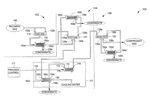
[0019] Figure 1 illustrates a turbomachine system 100 according to an
exemplary embodiment of
the present disclosure. For purposes of this disclosure, a turbomachine may
include any rotating
machinery configured to act on or with a gas, such as a turbine, compressor,
turboset, etc. The
turbomachine system 100 may include a plurality of stages 102, 104, and 106,
which may include
compressors 110, 120, and 130, respectively. In an exemplary embodiment,
compressor 110 may
be a D16A6 model number compressor manufactured by Dresser-Rand Company,
compressor 120
may be a 016R7B model number compressor manufactured by Dresser-Rand Company,
and
compressor 130 may be a D12R9 model number compressor manufactured by Dresser-
Rand
Company. In other exemplary embodiments, compressors 110, 120, 130 may be any
compressor
manufactured by any manufacturer.
[0020] Compressor 110 may include two compressor inlets 132a-b and one
compressor outlet 133.
Further, compressor 120 may include two inlets 134a-b and two outlets 136a-b.
Compressor 130
may include two inlets 138a-b, and two outlets 139a-b. Other compressor
configurations are also
within the scope of the present disclosure.
[0021] The turbomachine system 100 may further include one or more cooling
units 150a-d. Each
of the cooling units 150a-d, may include a heat exchanger (not shown) that is
configured to cool a
process gas to a temperature and pressure below the dew point, thereby causing
formation of
condensate. For example, each of the cooling units 150a-d may include water-
cooled heat
exchangers, such as shell and tube configurations. Each of the cooling units
150a-d may include
air-cooled heat exchangers rather than water-cooled heat exchangers. In
another exemplary
embodiment, the cooling units 150a-d may include refrigeration units in lieu
of heat exchangers.
The cooling units 150a-cl may include any conventional heat exchanger
configuration. Each cooling
4
CA 02763512 2011-11-24
WO 2010/138403 PCT/US2010/035721
unit 150a-d may include one cooling unit inlet 152a-d and one cooling unit
outlet 154a-d,
respe-ctiV-ely. Further, each cooling unit 150a-d may include a
condensate¨diSCharge158a=d7--
respectively. Each cooling unit 150a-d may also include one or more demisters
(not shown) that
are configured to remove condensate from the process gas. The cooling units
150a-d may also be
configured to collect and subsequently remove condensate using conventional
methods of
removing condensate from the cooling unit (e.g., a drain, evaporation, etc.).
[0022] Cooling unit 150c may also include a cooling water inlet 156 that
provides cool water to the
cooling unit 150c. Other cooling unit configurations are also within the scope
of the present
disclosure. For example, each cooling unit 150a-d may be any type of cooling
unit that may be
configured to cool gas to a temperature and pressure below the dew point, and
thereby cause
formation of condensate.
[0023] The heat exchanger (not shown) of cooling unit 150, may be referred to
herein as a "primary
heat exchanger." The primary heat exchanger may be configured to cool a
process gas to a
temperature and pressure below the dew point. Cooling unit 150c and heating
unit 170 may form a
moisture removal unit 171. Heating unit 170 may include a "secondary heat
exchanger" (not
shown) that is configured to heat a process gas to a temperature and pressure
above the dew point,
and thereby cause evaporation of condensate. Heating unit 170 may include an
inlet 174, which
receives output from outlet 154c of cooling unit 150c. Further, heating unit
170 may include an
outlet 176 that is coupled to compressor inlet 138a. Other heating unit
configurations are also
within the scope of the present disclosure. Furthermore, cooling unit outlet
153c may be coupled to
heat exchanger inlet 175, and a valve 178 may be coupled between the cooling
unit outlet 153c and
the heat exchanger inlet 175.
[0024] A process control mechanism 177 may be communicably coupled to the
moisture removal
unit 171. Each of the compressors 110, 120, 130 may be coupled to cooling
units 150a-d and
heating unit 170. For example, according to an exemplary embodiment, the
compressors 110, 120,
130 may be coupled to the cooling units 150a-d and heating unit 170, as shown
in Figure 1 and
described herein, Compressor 110 may be coupled to an incoming process gas
source 180, which
is configured to provide process gas at compressor inlets 132a-b. Compressor
outlet 133 may be
coupled to cooling unit inlet 152a. Cooling unit outlet 154a may be coupled to
compressor inlet
134a, Each of the condensate discharges 158a-d may optionally be coupled to a
condensate
recycling system (not shown). The condensate recycling system may direct all
removed
condensate to a single location.
[0025] Compressor outlet 136a may be coupled to cooling unit inlet 152b, and
cooling unit outlet
154b may be coupled to compressor inlet 134b. Further, compressor outlet 136b
may be coupled
to cooling unit inlet 152c. Cooling unit outlet 154c may be coupled to heating
unit inlet 174, and
heating unit outlet 176 may be coupled to compressor inlet 138a.
CA 02763512 2011-11-24
WO 2010/138403
PCT/US2010/035721
[0026] Compressor outlet 139a may be coupled to cooling unit inlet 152d, and
cooling unit outlet
154d may be co-Lk:ladle-compressor Finallrcompressor outlet 139b may be
coupled-to
another turbomachine system 100 component, such as a cooling unit or a
compressor, in an
additional compressor stage that is not shown in Figure 1 in an exemplary
embodiment, the
compressor 130 may be the final stage of a multi-stage compressor system,
Other coupling
configurations among the compressors 110, 120 and 130, the cooling units 150a-
d, and the heating
unit 170 are also possible according to other exemplary embodiments of the
present disclosure.
[0027] Operation of the turbomachine system 100, according to an exemplary
embodiment, may
begin at stage 102, wherein incoming process gas may be provided to the
compressor inlets 132a-
b. The compressor 110 may compress the process gas, and may direct the process
gas from
compressor outlet 133 to cooling unit inlet 152a. The cooling unit 150a may
lower the temperature
and pressure of the process gas below the dew point to produce condensate, and
remove the
resulting condensate from the process gas. Various conventional methods may be
used to remove
condensate from the process gas (e.g., demisters). The removed condensate may
collect at
condensate discharge 158a. At the condensate discharge 158a, the condensate
may be
evaporated, or directed to a recycling system (not shown), The process gas may
then proceed to
stage 104 by flowing from cooling unit outlet 154a to inlet 134a of compressor
120.
[0028] According to an exemplary embodiment, in stage 104, the compressor 120
may further
compress the process gas received from the cooling unit 15Da. The process gas
may then exit
compressor outlet 136a and flow to cooling unit inlet 152b. Cooling unit 150b
may once again
lower the temperature and pressure of the process gas below the dew point to
form condensate and
remove the condensate from the process gas. The cooling unit 150b may use
various conventional
methods of removing condensate from the process gas (e.g., demisters). The
removed condensate
may collect at condensate discharge 158b. At the condensate discharge 158b,
the condensate
may be evaporated, or directed to a recycling system (not shown). The process
gas may then flow
from cooling unit outlet 154b to compressor inlet 134b, where the process gas
may be compressed
even further.
[0029] The moisture removal unit 171 may further dehydrate the process gas.
The process gas
may flow from compressor outlet 136b to cooling unit inlet 152c. Cooling unit
150c may cool the
process gas to a temperature and pressure below the dew point. As a result of
the cooling, water
vapor in the process gas becomes condensate. The cooling unit 150c may use
various
conventional methods of removing condensate from the process gas (e.g.,
demisters).
[0030] in an exemplary embodiment, cooling the process gas may produce
residual heat. The
residual heat may be transferred to the cooling water, thereby producing
heated water. The heated
water may be directed to the inlet 175 of heating unit 170. In an exemplary
embodiment, a portion
of the removed condensate may collect at condensate discharge 158c, At the
condensate
6
CA 02763512 2011-11-24
WO 2010/138403 PCT/US2010/035721
discharge 158c, a portion of the condensate may be evaporated, or directed to
a recycling system
(notshown).
[0031] The process gas may flow from cooling unit outlet 154c to heat
exchanger inlet 174. The
secondary heat exchanger of the heating unit 170 may be configured to vaporize
any condensation
remaining in the process gas by heating the process gas and any remaining
condensate to a
temperature and pressure above the dew point.
[0032] According to an exemplary embodiment, the heating unit 170 may use the
heated water to
heat the process gas. For example, the temperature of the process gas entering
the cooling unit
150c at cooling unit inlet 152c may be about 300 F, and the temperature of the
cooling water
entering the cooling unit 150c at cooling unit inlet 156 may range from
ambient temperature to
about 110 F. If the process gas and the cooling water flow in the cooling unit
150c according to a
counter flow setup, the exiting water temperature will have a temperature that
is intermediate
between the incoming water temperature and the incoming gas temperature.
[0033] If the heat exchanger of the cooling unit 150c (not shown) is properly
designed to the heat
load, the exiting water temperature will approach the incoming gas
temperature. For almost all
gases, the exiting water will likely contain adequate heat content to
evaporate the remaining
condensate. Even with co-current flow, there will likely be enough heat in the
exiting water to
evaporate the remaining condensate, However, the heat transfer area of the
heating unit 170 will
need to be larger than with the co-current flow scenario than the counter-
current flow scenario.
[0034] In order to minimize the loss of compression efficiency that may result
from (1) the pressure
loss in going through a second heat exchanger, and (2) the temperature rise of
the process gas in
the heating unit 170, the heating unit 170 may be configured to minimize the
pressure drop, and
may use a controlled heat input to achieve the target temperature increase.
[0035] Alternatively, to compensate for the loss of compression efficiency
that may result from
heating the process gas above the dew point, the process gas can be cooled to
a temperature that
is several degrees lower than the dew point temperature before moving the gas
to the next
compressor, and then heating the process gas to above the dew point.
[0036] In an exemplary embodiment, the heating unit 170 may use means other
than heated water
to heat the process gas, including without limitation rod or wire heaters,
electricity, gaseous fuel, or
fuel oil. As may be appreciated, each means for heating the process gas may be
used alone or in
combination. The other means for heating the process gas may be controlled by
either the heating
unit 170 or a process control mechanism as described above.
[0037] If the quantity of water to be removed and the composition and quantity
of gases involved
are known, then it may be possible to calculate the amount of energy required
to heat the process
gas to a temperature and pressure above the dew point. In an exemplary
embodiment, if such
variables are unknown, it may be possible to determine their values, because
heat capacities of
7
CA 02763512 2011-11-24
WO 2010/138403
PCT/US2010/035721
most commercial gas mixtures are well known, or may be estimated. Furthermore,
it may be
possible to calculate the amount of heat necessary to heat the process gas and
any condensate
present in the composition to a temperature and pressure above the dew point,
even if the only
known variables are the water content of the incoming gas and the quantity of
water that was
condensed and removed. Such variables may be determined via conventional
sensors located at
various places in the turbomachine system 100.
[0038] In an exemplary embodiment, the process control mechanism 177 may be
communicably
coupled to a sensor (not shown) that is configured to detect the quantity of
water still present in the
process gas. The process control mechanism 177 may estimate the amount of
energy required to
vaporize water remaining in the process gas based on input from a sensor (not
shown), and may
control valve 178, so as to regulate the amount of heated water entering the
heating unit 170. For
example, the process control mechanism may control the valve 178, and thereby
control the
amount of heated water entering the heating unit 170, based on readings of
temperature and water
content of the gas exiting the heating unit 170.
[0039] A "Sereda" humidity sensor, or other similar sensor, can be used to
determine if the gas
leaving the heating unit 170 contains condensate. The process control
mechanism 177 may then
adjust components of the turbomachine system 100 based upon data provided by
the sensor. For
example, depending on the data provided by the sensor, the process control
mechanism 177 may
lower the temperature of the cooling unit 150c, raise the temperature of the
heating unit 170, and/or
increase the efficiency of a demister unit. Furthermore, the process control
mechanism 177 may
control the flow rate of heating and cooling water based upon feedback loops
that are
communicably coupled to temperature sensors.
[0040] In an exemplary embodiment, the secondary heat exchanger of the heating
unit 170 may
heat the process gas to a temperature that is about 5 F to about 10 F higher
than the temperature
of the process gas entering the heating unit 170. For example, the temperature
of the process gas
entering the heating unit 170 may be about 115 F and the temperature of the
process gas after
heating may be about 120 F.
[0041] A moisture removal unit similar to the moisture removal unit 171 may
also be used at other
locations of the turbomachine system 100. In some embodiments, implementation
of multiple
heating units 170 in a back-to-back configuration may be necessary to prevent
corrosive conditions
in locations of the turbomachine system 100 that may be more prone to
corrosion, for example, at
the initial stages of a compressor train. The corrosion is typically more
severe during the initial
stages of compression, because liquid water is most likely to be present in
the process gas during
the initial stages. Corrosion can also be problematic in later stages of
compression for very wet
gases, or when condensate is formed from process upsets, shut downs and
startups that allow
cooling of a gas below its dew point in a given stage of compression,
8
CA 02763512 2011-11-24
WO 2010/138403 PCT/US2010/035721
[0042] In an exemplary embodiment, the heating unit 170 may include a first
heating unit and a
second heating-uhrWifereiffthe second heating unit receives process gas frOrii
the-firstlie-ating-
unit, and heats the process gas and any remaining condensate to a temperature
and pressure that
is above the dew point. As an added benefit, utilizing a heating unit 170 may
be less expensive and
safer than using more corrosion-resistant materials in a turbomachine system
100.
[0043] The heating unit 170 may be built from the same material as the primary
heat exchanger of
cooling unit 150c. As a result of the relatively small size and simplicity of
the heating unit 170 as
compared to the heat exchanger present in cooling units 150a-d, the heating
unit 170 may be
relatively inexpensive to implement and maintain. Care should be taken to not
oversize the heat
exchanger of the cooling unit 150c with respect to the heating unit 170. Also,
the amount of cooling
water provided to the cooling unit 150 at inlet 156 should be monitored so
that the temperature of
the heated water provided at outlet 153c has enough heat content,
[0044] Still referring to Figure 1, the process gas may flow from heat
exchanger outlet 176 to
compressor inlet 138a. Compressor 130 may compress the process gas, and direct
the process
gas from compressor outlet 139a to cooling unit inlet 152d. Cooling unit 150d
may cool the process
gas and remove condensate using the methods described above with respect to
cooling units 150a-
c. The cooling unit 150d may direct the process gas from cooling unit outlet
154d to compressor
inlet 138b. Compressor 130 may recompress the process gas, and may either
direct the process
gas to another component of the turbomachine system 100, or may provide the
process gas to
another system for further processing.
[0045] Figure 2 shows an exemplary method 200 of removing water from a process
gas according
to an exemplary embodiment. The method 200 may include a primary stage 210 and
a secondary
stage 220. The primary stage 210 may include a step 250, at which process gas
may flow to a
primary heat exchanger, such as the heat exchanger present in the cooling unit
150c (not shown)
described above with respect to Figure 1. The primary heat exchanger may lower
the temperature
of the process gas to a first temperature that causes water vapor in the
process gas to form water
condensate, as at step 260. The first temperature is below the dew point
temperature. The heat
exchanger may be any heat exchanger known in the art, including without
limitation an air-cooled
heat exchanger and a water-cooled heat exchanger. In another exemplary
embodiment, instead of
using a heat exchanger, the process gas may be cooled using a refrigeration
unit.
[0046] Further, the primary stage 210 may also include a step 270, wherein
water condensate may
be removed from the process gas. In an exemplary embodiment, removal of the
water condensate
may be performed by one or more demisters using conventional methods. The
process of cooling
the process gas at step 260 may produce residual heat, which may in turn heat
the cooling water to
form heated water. This heated water may be used in a later step of method
200, as described
below.
9
CA 02763512 2011-11-24
WO 2010/138403 PCT/US2010/035721
[0047] The method 200 may continue to the secondary stage 220. The secondary
stage 220 may
include a step 280, Wherein tl--fe-p-roc-e-ss-gasnay-flow-to-a heating-unksuch
as the-heating unit 170
described above with respect to Figure 1. In an alternate embodiment, the
process gas may be
cooled further prior to step 280. At the secondary stage 220, a secondary heat
exchanger of the
heating unit may be configured to heat the process gas to a temperature and
pressure above the
dew point, thereby causing a portion of any remaining condensate that is
present in the process gas
to evaporate. This may further reduce the amount of remaining water condensate
within the process
gas, and may reduce the potential of corrosion in a turbomachine.
[0048] The amount of heat required to evaporate any condensate remaining in
the process gas
may depend on the efficiency of the primary heat exchanger and the associated
demisters used to
remove the condensate in the primary stage 210. Further, the heat required to
evaporate the
remaining condensate may be partially or wholly provided by the heated water
produced by the
primary heat exchanger at step 260. In an exemplary embodiment, rod or wire
heaters, electricity,
gaseous fuel, or fuel oil may be used to heat the process gas leaving the
heating unit. All of the
foregoing are means for heating the process gas leaving the heating unit.
[0049] In an exemplary embodiment of the method 200, in the secondary stage
220, the process
gas may be heated to a temperature that is about 5 F to about 10 F higher than
the temperature of
the process gas entering the secondary stage 220. For example, the temperature
of the process
gas entering the secondary stage 220 may be about 115 F and the temperature of
the process gas
after heating may be about 120 F or higher.
[0050] Conditions that may be conducive to corrosion may also be present
during startup and/or
shutdown of a turbomachine system. For example, when a turbomachine system is
shut down, as
the pressure falls throughout the turbomachine system, the temperature in the
turbomachine
system may also fall. Each of the various turbomachine system components may
progressively
reach the dew point as the system shuts down, resulting in the formation of
condensation from any
water vapor that is present in the process gas. If precautions are not taken
to dry the turbomachine
system components after condensation occurs, the moisture may result cause
corrosion, such as
Sulfide Stress Cracking or general corrosion.
[0051] Figure 3 shows a turbomachine system 300 according to another exemplary
embodiment of
the present disclosure. The turbomachine system 300 may be similar to the
turbomachine system
100, as described above. Reference numbers that are used in Figure 1 are also
used in Figure 3 to
identify identical components.
[0052] Turbomachine system 300 may further include a dry gas source 310 and a
dry gas transport
320. In an exemplary embodiment, the dry gas transport 320 may include a pipe
that fluidicly
couples the dry gas source 310 to compressor inlets 132a-b, and may also
include a valve 322 that
is coupled to the dry gas transport 320.
CA 02763512 2011-11-24
WO 2010/138403 PCT/US2010/035721
[0053] The turbomachine system 300 may also include an outside water source
330 and an outside
watertransp-ort-340 that coOples- the oUtside water source 330 to the inline
water heater 350-.-The'
inline water heater 350 may be coupled to the heating unit 170. A valve 360
may be coupled
between the inline water heater 350 and the heating unit 170.
[0054] The process control mechanism 177 may be communicably coupled to the
valves 178, 322,
360, The turbomachine system 300 may also include a moisture removal unit 370
located at the
front of the compressor train between the process gas source 170 and the
compressor 110. The
moisture removal unit 370 may be similar to heating unit 170 of the moisture
removal unit 171
described above with respect to Figure 1, In an exemplary embodiment, the
moisture removal unit
370 may include a cooling unit 378 and a heating unit 379, The heating unit
379 may be coupled to
the valve 360. The valve 360 may also be coupled to the inline water heater
350 and the heating
units 170.
[0055] An exemplary operation of the turbomachine system 300 may include
providing a process
gas to the cooling unit 378 of moisture removal unit 370. The operation of the
cooling unit 378 and
the heating unit 379 may be similar to the operation of the cooling unit 150c
and the heating unit
170, respectively, as described above with respect to Figure 1. Placing the
moisture removal unit
370 at the head of the turbomachine system 300 facilitates maintaining
operating temperatures and
pressures in the compressor train above the dew point during startup of the
turbomachine system
300. The turbomachine system 300 may then operate as described above with
respect to Figures 1
and 2.
[0056] During the shutdown of turbomachine system 300, the turbomachine system
300 may
provide a dry gas from the dry gas source 310 to the compressor inlets 132a-b.
The valve 322 may
gradually increase the quantity of dry gas provided to the compressor inlets
132a-b as the quantity
of process gas in the turbomachine system 300 decreases. A process control
mechanism 178 may
be configured to control the valve 322 based upon environmental conditions of
the turbomachine
300. For example, the process control mechanism 177 may be communicably
coupled to sensors
configured to detect the quantity of process gas in the turbomachine system
300.
[0057] As discussed above, residual heat generated by the cooling unit 150c
during cooling of the
process gas may be used to heat removed condensate, and thereby create heated
water. During
shutdown, the turbomachine system 300 may increase the amount of heated water
that is provided
from the cooling unit 150c to the heating unit 170. As compressors 110, 120,
130 are shut off,
beginning at the back of the compression train and moving towards the front of
the compression
train, valve 178 may control the quantity of heated water provided to the
heating unit 170. Valve
178 may increase the quantity of heated water directed to the heating unit 170
in order to keep the
temperature and pressure of downstream component environments above the dew
point. The
process control mechanism 177 may be configured to control valve 178 based
upon environmental
11
CA 02763512 2011-11-24
WO 2010/138403 PCT/US2010/035721
conditions in the turbomachine 300. For example, the valve 178 may control the
amount of heated
water entering th itiñi unit 170 of
temperature-and-water-conteraif tl'ie gas
exiting the heating unit 170.
[0058] In addition to increasing the amount of heated water that is provided
from the cooling unit
1500 to the heating unit 170, additional heated water may be provided from
other sources. For
example, the outside water source 330 may provide water to the inline water
heater 350, and the
inline water heater 350 may heat the water, and provide the heated water to
the heating units 360,
379. The valve 360 may control the provision of the heated water from the
inline water heater 350
to the heating units 360, 379.
[0059] In another exemplary embodiment, process control mechanism 178 may be
configured to
control the valve 360 based upon environmental conditions in the turbomachine
300. A person of
ordinary skill in the art may utilize modeling tools to design a process
control mechanism that
efficiently coordinates the injection of gas and provision of heated water to
components of the
turbomachine system 300 upon shutdown.
[0060] Figure 4 shows an exemplary embodiment of a method 400 for reducing
corrosion resulting
from the startup and shutdown stages of a turbomachine system. The method 400
may include
starting the turbomachine system at step 402. At step 404, a process gas may
be provided to a
moisture removal unit that is placed at the front of the turbomachine system,
such as moisture
removal unit 370 shown in Figure 3. After continued operation, the
turbomachine system may be
shut down at a step 406. When the turbomachine system is shut down, a dry gas,
such as nitrogen
or sweet gas, may be injected into the turbomachine system at step 408 to
replace the decreasing
amount of process gas that is entering the turbomachine system 300. The
turbomachine system
may also increase the amount of heated water provided from cooling units to
heating units at step
410. At a step 412, heated water from an outside water source may be provided
to the heating
units as the amount of heated water generated by the cooling units decreases.
The heated water
from the outside water source compensates for the reduced amount of heated
water that is
provided by the cooling units to the heating units during the shut down of the
turbomachine system.
[0061] In a case study of a turbomachine system similar to the turbomachine
system 100 shown in
Figure 2, the gas coming into a Dl 2R9 compressor manufactured by Dresser-Rand
Company, at
stage 8, was 355 psig, 120 F, and wet. The calculated partial pressure of
hydrogen sulfide was 20
bar, which is greater than that currently allowed by NACE for 17-4 PH
stainless steel, However, if
the gas were dry, and could be guaranteed to always be dry, 17-4 PH stainless
steel could be used
to manufacture the compressor.
[0062] In this study, there was a cooling unit before stage 8, which dropped
the temperature of the
gas from 297 F to 120 F while the pressure dropped from 361 to 355 psig.
Assuming 90% of the
12
CA 02763512 2015-05-14
moisture was removed via this cooling unit, the gas entering the D12R9
compressor was still
wet. The use of a heating unit could ensure that the gas entering the
compressor is dry.
[0063] Assuming the cooling unit is a water-cooled heat exchanger, such as a
tube and shell
heat exchanger, then a secondary tube and shell heat exchanger can be added to
raise the
gas temperature before entering the D12R9 compressor. Assuming the cooling
unit has the
gas and cooling water flowing in a counter-current manner, then the water
exiting the heat
exchanger of the cooling unit could be well over 200 F, and more likely in
excess of 250 F.
Some of this water could be fed into the heating unit to raise the temperature
of the gas.
[0064] Assuming the temperature of the gas is raised from 120 F to 130 F in
the heating unit,
and that there is an additional pressure drop across the heating unit equal to
what occurred in
the heat exchanger of the cooling unit, then the gas entering the D12R9
compressor will be
130 F and 350 psig. Under these conditions, the gas will be dry. It is
estimated that the
pressure drop across the heating unit could cause about a one half percent
drop in
compressor efficiency. This compressor efficiency decrease may be lessened by
cooling the
process gas even further below the dew point prior to heating the process gas.
[0065] The exemplary embodiments of methods and systems of the present
disclosure may
be inexpensive to manufacture and operate in comparison to other dehydration
systems. One
reason for this is that exemplary embodiments of the present disclosure may
include relatively
simpler component parts as compared to those used in other dehydration
systems. Further,
the exemplary embodiment of the present disclosure may ease integration into
existing
systems, because the primary heat exchanger may already exist in the
compressor system to
cool the process gas. Thus, only the heating unit may need to be added to the
system.
Nonetheless, it should be understood that the exemplary embodiments of the
present
disclosure may also be used in conjunction with other dehydration systems to
reduce
corrosion in compressor systems.
[0066] Although the present disclosure has described embodiments relating to
specific
compressors, it is understood that the apparatus, systems and methods
described herein
could applied to other turbomachine environments.
[0067] The foregoing has outlined features of several embodiments so that
those skilled in the
art may better understand the detailed description that follows. Those skilled
in the art should
appreciate that they may readily use the present disclosure as a basis for
designing or
modifying other processes and structures for carrying out the same purposes
and/or achieving
the same advantages of the embodiments introduced herein. Those skilled in the
art should
also realize that such equivalent constructions do not depart from the scope
of the present
disclosure, and that they may make various changes, substitutions and
alterations herein
without departing from the scope of the present disclosure.
13