Note: Descriptions are shown in the official language in which they were submitted.
CA 02763590 2011-11-25
WO 2010/143213 PCT/IT2009/000259
1
DESCRIPTION
"MOULDING METHOD OF A COMPONENT AND COMPONENT
THEREOF"
[001] The present invention relates to the
moulding method of a component and relative
component made using said moulding method.
[002] It is known of in the art to make moulded
components comprising a body and a covering or
insert, for example in fabric or leather, joined at
least partially to the body.
[003] According to the technique known by the
name of `back injection', the insert is fitted
onto the die of the mould using hooks positioned
outside the injection chamber; so that the surface
of the insert is always bigger than the surface of
the component body.
[004] The mould is closed therefore blocking the
insert at its respective fastenings and the plastic
material is injected from the back so as to press
the insert against the die of the mould, making the
insert adapt to said mould.
[005] The pressure of the injection is such as
not to pierce the covering of faux fabric or faux
leather which is therefore solidly joined to the
CA 02763590 2011-11-25
WO 2010/143213 PCT/IT2009/000259
2
component body.
[006] When the moulding cycle is completed, the
piece is sent to a (laser or manual) cutting
station to eliminate the part of the covering
excess to the outline of the component body; lastly
the piece is sent to a (manual or automatic) gluing
or attachment station to "seal" the free edges of
the covering onto the back of the piece, for
example by gluing or stapling.
[007] The state of the art technique presents
numerous drawbacks and limitations.
[008] First of all, the considerable production
waste. Moreover, the known state of the art method
foresees various processing phases essentially
connected with removal of the strips of covering in
excess of the body outline, following extraction of
the piece from the mould.
[009] High processing costs due overall to the
time, waste, and presence of specific cutting
stations of the covering result.
[0010] The purpose of the present invention is to
resolve the drawbacks mentioned with reference to
the known technique.
[0011] Such drawbacks are resolved by a method
according to claim 1 and by a component according
CA 02763590 2011-11-25
WO 2010/143213 PCT/IT2009/000259
3
to claim 19.
[0012] Other embodiments of the method and of the
component according to the invention are described
in the subsequent claims.
[0013] Further characteristics and advantages of
the present invention will be more easily
comprehended from the description below, made by
way of a preferred, non-limiting example of
embodiment, wherein:
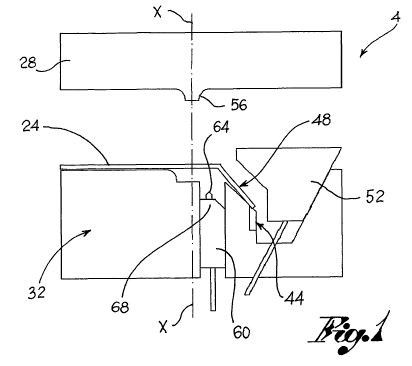
[0014] Figures 1-5 shows schematic cross-section
views of successive moulding phases of a component
according to the method of the present invention;
[0015] Figure 6 shows an enlarged view of a part
of a mould according to the present invention.
[0016] With reference to the aforesaid figures
reference numeral 4 globally denotes a mould for
injection moulding, specifically for the production
of a component 8.
[0017] The component 8 comprises a component body
12 having a first portion 16 and a second portion
20, and an insert 24 able to cover at least
partially said component body 12.
[0018] The mould 4 comprises a die 28 and a punch
32 reciprocally moving according to an axial
direction X-X of opening/closing of the mould 4.
CA 02763590 2011-11-25
WO 2010/143213 PCT/IT2009/000259
4
[0019] The die 28 and the punch 32, in a closed
configuration, define a first and a second
injection chamber 36,40 which respectively
reproduce in negative the first and the second
portion 16,20 of the component body 12 to be
moulded.
[0020] The injection chambers 36,40 are defined by
the die 28 and the punch 32, and are beside each
other.
[0021] According to one embodiment, said insert 24
is a sheet of fabric and/or faux leather able to
cover the moulded component 8 at least partially.
[0022] Said insert 24 may also be a reinforcement
element of the component 8, such as a mesh, a
preliminary mould and/or metal sheet.
[0023] According to one embodiment, the insert 24
is attached to the inside of the mould 4 by means
of a suction device 44 able to create negative
pressure between an attachment portion 48 of the
insert 24 and the punch 32.
[0024] According to a further embodiment, the
insert 24 is blocked inside the mould 4 by a moving
block 52 which clamps it for example to the punch
32 at an attachment portion 48 of the insert 24.
[0025] According to one embodiment, the die 28 of
CA 02763590 2011-11-25
WO 2010/143213 PCT/IT2009/000259
the mould 4 comprises a separation wall 56 between
the first and second injection chamber 36,40; as
better described below, the wall 56 influences the
insert 24 and co-operates with it to prevent the
5 passage of the injected material between the first
and the second injection chamber 36,40.
[0026] The mould 4 comprises, in addition, a
moving cursor 60 able to tauten the insert 24
inside the mould 4. The cursor 60 co-operates with
the wall 56 and with the insert 24 to insulate the
two injection chambers'36,40 from each other.
[0027] According to one embodiment, the cursor 60
is aligned with the wall 56 so that, in an
extracted configuration, it forms, with the insert
24 a barrier to the passage of the first injection
in the second injection chamber 40.
[0028] Preferably, the cursor 60 is fitted with at
least one nipper 64 positioned on a work head 68
which comes into contact with the insert 24 in the
extracted configuration of the cursor 60, to make
at least one hole on the insert 24.
[0029] According to one embodiment, the cursor 60
comprises at least one tooth 72 able to grasp the
insert 24, so as to facilitate the phase of
tautening the insert 24 and of making through holes
CA 02763590 2011-11-25
WO 2010/143213 PCT/IT2009/000259
6
on the insert 24.
[0030] Preferably, the cursor 60 is positioned
between the wall 56 and the attachment portion 48
of the insert 24.
[0031] In other words, in the closed configuration
of the mould 4, the insert 24 is blocked both by
the punch 32, at the attachment portion 48, and by
the wall 56.
[0032] The cursor 60, by means of the work head
68, acts on the portion of insert projecting
between the punch 32 and the wall 56, tautening it
and making the holes using nippers 64.
[0033] The method of the present invention
comprises the phases of positioning the insert 24
inside the first injection chamber 36, for example
resting it on the punch 32 at the first injection
chamber 36 (figure 1).
[0034] The insert 24 is then blocked into position
by the suction device 44 and/or moving block '52
which is made to hit against the punch 32, pinching
it in the middle of the attachment portion 48 of
the insert 24 (figure 2).
[0035] The insert 24 is predisposed so as to
separate the first injection chamber 36 from the
second injection chamber 40 which reproduces in
CA 02763590 2011-11-25
WO 2010/143213 PCT/IT2009/000259
7
negative the second portion 20 of the component
body 12 to be moulded.
[0036] , The first injection of plastic material is
made inside the first injection chamber 36.
Preferably, the first injection is made from the
side of the punch 32 so as to fill the first
injection chamber 36 and compress the insert 24
against the die 28, joining the insert 24 at the
first injection (figure 3).
[0037] During the first injection, the cursor 60
is in an extracted position so as to tauten the
insert 24 pinched between the wall 56 and the block
52.
[0038] Preferably, the cursor itself advances so
as to form a barrier to the passage of the first
injection which remains confined in the first
injection chamber 36.
[0039], Following the first injection, at least one
hole is made in the portion of insert occupying the
second injection chamber 40, .so as to put the
second injection chamber 40 in communication with
the first moulded portion 16.
[0040] Preferably, the holes in the insert 24 are
made by the nippers 64 placed on the work head 68
of the cursor 60 during the extraction of the
CA 02763590 2011-11-25
WO 2010/143213 PCT/IT2009/000259
8
cursor 60 to tauten the insert 24 (figure 3).
[0041] The tautening of the insert is in turn
facilitated by the teeth 72 placed on the cursor 60
which catch in the insert and pull it with the
movement of the.cursor 60.
[0042] After the solidification of the first
injection, the cursor 60 moves rearwards so as to
free the holes made by the nippers 64 on the
insert, and the second injection of plastic
material is made inside the second injection
chamber 40. In this phase, the cursor 60 defines
the second injection chamber 40, together with the
die 28 and the punch 32.
[0043] The injected material. traverses at least
one hole so as to join the second moulded portion
to the.first moulded portion 16 and to include
the portion of insert 24 lodged in the second
chamber .(figure 4).
[0044] :Spe-cifically, the second- injection may
20 cause .breakage of the insert 24 at the holes
previously made;- in any case the torn edges of. the
insert 24 are included in the second injection.
[0045] The second injection is made directly into
the second injection chamber 40, for example on the
side opposite the wall 56 which defines the first
CA 02763590 2011-11-25
WO 2010/143213 PCT/IT2009/000259
9
and the second injection chamber 36,40.
[0046] The first and the second injections are
made injecting plastic materials compatible with
each other, so as to produce adhesion between the
first and second portions 16,20 of the component
body 12. In other words, the second injection
traverses the holes in the insert and joins with
the first portion 16 creating the moulded component
in a single piece.
[0047] After having made the second injection, the
mould 4 is opened and the component 4 expelled in a
single piece, comprising the first portion 16, the
insert 24 and the second portion 20.
[0048] For example, the expulsion phase of the
component 8 from the mould 4 may be facilitated by
the block 52 (figure 5).
[0049] As may be seen from the description, the
method of the present invention makes it possible
to overcome the drawbacks presented in the 'known
technique.
[0050] Advantageously, the piece moulded according
to the present invention, once extracted from the
mould requires no further processing and is ready
for assembly.
[0051] In fact the edges of insert comprised
CA 02763590 2011-11-25
WO 2010/143213 PCT/IT2009/000259
between the first and the second portion are
directly included in the second injection; any
edges not included are in any case located on the
inner side of the component, that is on the side
5 opposite the insert and therefore not on view,
thereby requiring no subsequent removal operations.
All the manual or automatic cutting phases
subsequent to extraction of the piece from the
mould are thus eliminated.
10 [0052] As a result, the piece extracted from the
mould is already ready for assembly in that it
requires no further processing in terms of cutting
or attachment to any other part.
[0053] This way production costs and times of
moulded pieces comprising coverings are
considerably reduced.
[0054] The spheres of application of the present
invention are varied. For example, bodywork parts
of vehicles may be made, such as door panel parts
or car mouldings.
[0055] In addition, it is also possible to make
parts such as airbag pieces, where the mesh holding
the cover which explodes after the airbag opens, is
used as the insert.
[0056] It is also possible to make parts such as
CA 02763590 2011-11-25
WO 2010/143213 PCT/IT2009/000259
11
engine sheaths, where a preliminary mould or metal
sheet is used as the insert.
[0057] A person skilled in the art may make
numerous modifications and variations to the
methods described above so as to satisfy contingent
and specific aims while remaining within the sphere
of protection as defined by the following claims.