Note: Descriptions are shown in the official language in which they were submitted.
1
AN ASSEMBLY SYSTEM FOR CONNECTING FURNITURE ELEMENTS
Technical field
The present invention relates to an assembly system for furniture, a g for
connecting
elements of a piece of furniture such as cupboard elements and the like
Background of the invention
Furniture like cupboards, bookshelves, loudspeakers and the like often
comprise plate
shaped wall sections, top elements and bottom elements, which are connected
along
the edges and thereby form spatial shapes
Since assembling of furniture requires different forms of tool and in some
cases
machinery, furniture is traditionally assembled at the factory where produced
and
subsequently delivered in an assembled state Transportation, handling and
storages
of such spatially shaped furniture require a great deal of space compared to
non-
assembled furniture elements, not least for furniture shops and end-users
Therefore, attempts have been made to deliver non-assembled furniture elements
which have to be assembled at the place of use, When the end-user receives the
furniture, it is typically packed with a set of assembly elements which often
comprises a
large amount of screws, nails and similar assembly features. First, the user
has to get
an overview of the large amount of pieces received. Subsequently, each piece
has to be
fastened correctly often by use of different tools. It often happens that
pieces are mixed
up so that assembling of the furniture elements has to be redone, or '
alternatively that the user has to live with a defective, and possibly
unstable and
lopsided furniture,
An example is described in applicant's International Patent Publication No. WO
2009-
044235 Al .
Summary of the inventor' =
It is an abject of the present invention to provide an improved assembly
system for
connecting furniture elements.
CA 2763841 2017-11-24
CA 02763841 2011-11-29
WO 2010/115967 PCT/EP2010/054668
2
In a first aspect, the invention provides a system for assembling a piece of
furniture,
the piece of furniture comprising a first plane wall element and a second
element, the
system comprising.
-an elongated track element defining a longitudinal direction, the
elongated track element including a recessed bottom wall and opposite front
flanges
defining there between a channel of a specific width, the recessed bottom wall
being
spaced at a specific distance behind said opposite front flanges and having a
plurality
of equidistantly spaced apart indentations or apertures, the elongated track
element
being attachable to or attached to, preferably being countersunk in the first
plane wail
element of the piece of furniture, and
-a fitting element having a main portion defining opposite parallel side
surfaces spaced apart a distance equal to or slightly smaller than the
specific width
and defining a front surface and an opposite rear surface, and the fitting
element
having an arresting pin extending outwardly from the rear surface of the main
portion
of the fitting element, further having a transversal bar and a length
exceeding the
specific width and having a maximum thickness smaller than the specific width,
the
transversal bar extending parallel with the front and rear surfaces of the
main portion
of the fitting element,
-the fitting element being mounted in and arrested relative to the
elongated track element in a three-step operation,
-a first step involving positioning the fitting element having the fitting
element positioned in front of the channel and having the transversal bar
orientated
parallel with the longitudinal direction and having the front and rear
surfaces of the
main portion of the fitting element extending parallel with the opposite front
flanges of
the elongated track element and introducing the transversal bar into the
channel of the
elongated track element,
-a second step involving rotating the fitting element while maintaining the
transversal bar within the channel of the elongated track element so as to
position the
transversal bar perpendicular to the longitudinal direction of the elongated
track
element and positioning the rear surface of the main portion of the fitting
element
juxtaposed the bottom wall of the elongated track element for allowing the
fitting
element to be shifted along the longitudinal direction relative to the
elongated track
element, and
-a third step involving receiving the arresting pin within a single
indentation or aperture of the bottom wall of the elongated track element so
as to
arrest the fitting element relative to the elongated track element
CA 02763841 2011-11-29
WO 2010/115967 PCT/EP2010/054668
3
The system offers a simple way of assembling the furniture, merely by
reorientation of
the fitting element relative to the elongated track element, whereby the use
of tools
can be avoided,
The elongated track element may be attached to the first furniture element at
the
factory where the furniture elements are produced A plurality of elongated
track
elements may be attached to each of the first furniture elements, e g by
providing a
set of elongated track elements in parallel at a surface of the first
furniture element
The elongated track element may be countersunk in a surface of the first
furniture
element To provide a plane surface, an upper surface of the elongated track
element
may form part of the furniture surface whereby the channel may extend in the
first
furniture element below the surface of the first furniture element. To
countersink the
elongated track element in the surface of the first furniture element, the
first furniture
element may be provided with an elongated groove with a cross sectional shape
which
matches the cross sectional shape of the elongated track element so that an
inner
surface of the groove is in contact with an outer surface of the elongated
track element
when the elongated track element is located in the groove
The elongated track element can be attached adhesively to the first furniture
element,
or the elongated track element may be interlocked in a groove in the surface
by
providing a cross sectional shape of the elongated track element which
cooperates
with a cross sectional shape of the groove, e,g to form a dovetail joint, or
the
elongated track element may be attached by nails, screws, rivets, etc
Alternatively or
additionally, the outer surface of the elongated track element may have a
frictional
coefficient, which reduces or prevents sliding of the elongated track element
in the
groove of the first furniture element In one embodiment, protrusions may be
provided
at the outer surface of the elongated track element to engage the inner
surface of the
groove The elongated track element may be formed of metal, e g aluminium, of
plastic or of other materials, e g. by an extrusion process
The elongated track element may comprise a flange portion defining an opening
Into
the channel and which allows passage of the first locking portion Into the
channel in
the open mutual orientation and which prevents movement of the first locking
portion
out of the channel in the closed mutual orientation.
CA 02763841 2011-11-29
WO 2010/115967 PCT/EP2010/054668
4
To enable assembling of several furniture elements, the fitting element may
further
comprise a second locking portion adapted to retain a second furniture element
In the open mutual orientation, the first locking portion is allowed passage
into and out
of the channel, e.g.by turning the fitting element 90 degrees relative to the
direction of
use and then inserting the first locking portion into the channel. In the
closed mutual
orientation, the fitting element may be attached to the elongated track
element, e.g by
turning the fitting element 90 degrees whereby the first locking portion may
be locked
in the channel by the flange portion. In the closed mutual orientation, the
first locking
portion is moveable in the axial direction within the channel. In the fixed
mutual
orientation, the first locking portion is locked immovably relative to the
elongated track
element
The fitting element may in the fixed mutual orientation form an essentially
plane
surface portion which is in level with the upper surface of the elongated
track element
The first locking portion may be provided as a T-shaped portion with a
transverse
portion extending perpendicularly to a main portion The main portion
may be shaped so that it extends in the axial direction when the fitting
element is in the
fixed mutual orientation, The second locking portion may form a protrusion
extending
from the plane surface portion of the fitting element, e,g extending
perpendicular to
the plane surface portion
The first furniture element may e g be a sidewall element or a back wall
element of a
cupboard or the like, whereas the second furniture element may be a shelf
element, a
top element, a bottom element, a door element, etc Thus, the assembly system
comprising the elongated track element and the fitting element may be used for
joining
a cupboard and the like. The assembly system may comprise different types of
fitting
elements for the same type of elongated track element As an example, one
fitting
element may be suitable for a shelf element, whereas another type of fitting
element
may be suitable for a door element, both types of fitting elements being
suitable for the
same elongated track element, e.g. an elongated track element which may be
attached to a first furniture element in the form of a sidewall element
When the sidewall elements with the countersunk elongated track elements have
been
produced at a factory, they could be packed together with a top element and a
bottom
element and possibly a number of shelf elements The top element and the bottom
CA 02763841 2011-11-29
WO 2010/115967 PCT/EP2010/054668
element may be formed with depressions or holes for receiving the second
locking
portion of the fitting element In a similar manner, the shelf elements could
be provided
with depressions or holes. A number of fitting elements may be located in the
package
and the package can be shipped to a buyer. The fitting elements may e g be
5 completely
identical elements, which are all provided with a first locking portion, which
can enter the channel in the elongated track element and be fixated therein
They may
further comprise a second locking portion, which can engage a depression or
hole in
the top and bottom elements or in the shelf elements The fitting elements may
also
have different second locking portions One group of the fitting elements may
have a
second locking portion which is adapted to engage the depressions or holes in
the top
and bottom elements, This second locking portion may in some embodiments form
an
upwardly extending protrusion with a conically shaped outer surface which can
enter
Into the depressions or holes and which thereby pulls the top or bottom
element
towards the sidewall element. Another group of the fitting elements may have a
second locking portion which can be attached e g. to a hinge for supporting a
door, or
the second locking portion may simply serve to be attached to any kind of
elements,
e.g.. by providing a body In which a screw or nail may be fastened
When the package is received, the user may attach the fitting elements at
various
places along the elongated track elements by inserting the first looking
portion in the
channel and by reorienting the fitting element until it is locked in a fixed
position
relative to the elongated track element Subsequently, the user may connect the
top
and bottom elements and optionally the shelf elements without using any tools
If all
the fitting elements are identical, almost nothing can go wrong, and if the
fitting
elements are different, it is not very critical if the user locates them
wrongly in the first
attempt The fitting elements will just have to be reoriented in the opposite
sequence
until the element can be removed from the elongated track element to be
repositioned
at a new location
In order to prevent movement of the fitting element in the axial direction
when the
fitting element and the elongated track element define the fixed mutual
orientation, the
fitting element and elongated track element may comprise locking features
adapted to
cooperate
The invention may provide a flexible assembly system according to which the
locking
features may provide a plurality of locking positions along the axial
direction of the
CA 02763841 2011-11-29
WO 2010/115967 PCT/EP2010/054668
6
elongated track element At these locking positions, movement of the fitting
element
may be prevented and the fitting element may be positioned optionally at one
of the
locking positions Providing a plurality of locking positions along the
elongated track
element may furthermore allow for the use of a plurality of fitting elements
in
combination with each elongated track element, whereby a first furniture
element may
be connected to a plurality of second furniture elements As an example, a
first
furniture element in the form of a sidewall element or a back wall element may
be
connected to a plurality of second furniture elements in the form of shelf
elements and
may further be connected to a top element and to a bottom element, each
element
being connected via a fitting element at a locking portion along the axial
direction,
in order to fixate the fitting element in the elongated track element, the
locking features
of the fitting element may comprise protrusions adapted to engage
corresponding
cavities in the channel
Alternatively or additionally, the locking features may comprise an indented
surface of
one of the fitting element and the elongated track element arranged to engage
a
projection or indentation in the other one of the fitting element and
elongated track
element The projection or indentation may in some embodiments form part of an
indented surface of the other part,
In some embodiments, the channel may form end portions on opposite side of an
intermediate portion in a cross section perpendicular to the axial direction
The end
portions may extend towards an opening into the channel, whereby the end
portions
may define the flange portion
The elongated track element may define a channel which is open at both ends
These
open ends may be dosed using end stops The fitting element may form these end
stops
In a simple embodiment, the channel may form a quadrangular shape in a cross
section perpendicular to the axial direction The channel may thus comprise a
front
wall, a rear wall and two sidewalls The opening may be formed in the front
wall in this
embodiment, the front wall and rear wall may be essentially parallel, and the
sidewalls
may be essentially parallel. Furthermore, the front and rear walls may be
perpendicular to the sidewalls..
CA 02763841 2011-11-29
WO 2010/115967 PCT/EP2010/054668
7
The cavities, which may be part of the locking features, may be formed in the
rear wall
of the channel Alternatively or additionally, the cavities may be formed in
the sidewalls
or the front wall The locking features of the fitting element may be
positioned in order
to fit into these cavities If the cavities are formed in the rear wall of the
channel, the
protrusions of the fitting element may be formed at the backside of the main
portion
In some embodiments, the second locking portion may be formed to engage a
depression or a hole of the second furniture element, whereby the second
locking
portion may be hidden when the first and second furniture elements are
connected
The fitting element may be shaped to reduce the distance between the first and
second furniture elements when the second locking portion engages the
depression or
hole of the second furniture element As an example, the second locking portion
may
comprise a protrusion having a conically shaped upper part, allowing the
fitting
element to attract the second furniture element when this element is attached
to the
second locking portion
In some embodiments, the fitting element may be used in connection with hinges
and
the like As an example, the second locking portion may be connected to a hinge
in
order to support a door element One part of the hinge may be connected to
cavities
provided at the front side of the second locking portion, while the other part
of the
hinge may be connected to a door element for a piece of furniture, e.g for a
cupboard
In a second aspect, the invention provides a piece of furniture being
assembled by the
use of the system according to any of the claims 1-6 and/or the fitting
element
according to claim 7 and/or the elongated track element according to claim 8.
In a third aspect, the invention provides a method of assembling the system
according
to claim 1 by performing the three-step operation of claim 1 in the sequence
step 1,
step 2, step 3
In a fourth aspect, the invention provides a method of disassembling the
system
according to claim 1 by performing the three-step operation of claim 1 in the
sequence
step 3, step 2, step 1..
Brief description of the drawings
CA 02763841 2011-11-29
WO 2010/115967 PCT/EP2010/054668
8
Embodiments of the invention will now be further described with reference to
the
drawings, in which.
Figs 1-la show a first embodiment of an elongated track element,
Figs 2-3 show a first embodiment of a fitting element
Figs 4-6 show the fitting element of Figs, 2 and 3 and an embodiment of an
elongated
track element,
Figs. 7-8 show a second embodiment of a fitting element,
Figs 9-12 show the fitting element of Figs, 7 and 8 and an embodiment of an
elongated track element,
Fig. 13 shows a third embodiment of a fitting element,
Figs.. 14-15 show a second embodiment of an elongated track element,
Fig 16 shows a piece of furniture including a system according to the present
invention,
Figs 17A and 17B show perspective views of a further embodiment of an
elongated
track element,
Figs. 17C-17H show elevational views of the elongated track element shown in
Figs
17A and 17B,
Figs 18A and 18B show perspective views of a further embodiment of a fitting
element
to be used in combination with the elongated track element shown in Figs 17A-
17H,
Figs 18C-18H show elevational views of the fitting element shown in Figs 18A
and
18B,
Figs 19A and 198 show perspective views of a shelf brick element to be built
into a
furniture element and to be used in combination with the fitting element shown
in Figs
18A-18H,
Figs 19C-19F show elevational views of the shelf brick element shown in Figs
19A-
198,
Figs 20A and 20B show perspective views of a connector element to be used in
combination with the elongated track element shown in Figs. 17A-17H,
Figs 20C-20H show elevational views of the connector element shown in Figs 20A
and 208,
Figs. 21A and 218 show perspective views of an alternative embodiment of the
connector element shown in Figs. 20A-20H,
Figs 21C-21H show elevational views of the connector element shown in Figs..
21A
and 21B,
CA 02763841 2011-11-29
WO 2010/115967 PCT/EP2010/054668
9
Figs. 22A and 22B show perspective views of an alternative fitting element to
be used
for supporting a tabletop and intended to be used in combination with the
elongated
track element shown in Figs 17A-17H,
Figs 22C-22H show elevational views of the alternative fitting element shown
in Figs
22A and 22B,
Figs 23A and 23B show perspective views of a connector element constituting a
blocker and intended to be used in combination with the elongated track
element
shown in Figs 17A-17H,
Figs 23C-23H show elevational views of the connector element shown in Figs..
23A
and 23B,
Figsõ 24A and 24B show perspective views of a further connector element
including
two closing magnets and intended to be used in combination with the elongated
track
element shown in Figs 17A-17H,
Figs 24C-24H show elevational views of the connector element shown in Figs.
24A
and 24B,
Figs 25A and 25B show perspective views of a further connector element to be
used
in combination with the elongated track element shown in Figs 17A-17H,
Figs 25C-25H show elevational views of the connector element shown in Figs.
25A
and 25B,
Figs 26A and 26B show perspective views of a further connector element for
connection to a side panel or blend panel and intended to be used in
combination with
the elongated track element shown in Figs. 17A-17H or alternatively the shelf
brick
element shown in Figs. 19A-19F,
Figs 26C-26H show elevational views of the connector element shown in Figs 26A
and 26B,
Figs 27A and 27B show perspective views of a further built-in connector for
use in
combination with the connector elements shown in Figs. 25A-25H, and
Figs 27C-27H show elevational views of the connector shown in Figs 27A and
27B.
Detailed description of the drawings
Figs. 1 and 2 show an example of an elongated track element 1 (Fig, 1) and an
example of a fitting element 2 (Fig. 2) for connecting a first and a second
furniture
element The elongated track element 1 is attachable to the first furniture
element and
defines a channel 3 extending in the axial direction. The fitting element 2
has a first
locking portion 4 and a second locking portion 5 The channel 3 comprises a
flange
portion 6 allowing passage of the first locking portion 4 into and out of the
channel 3
CA 02763841 2011-11-29
WO 2010/115967 PCT/EP2010/054668
Furthermore, the configuration of the flange portion 6 and the locking portion
4
prevents movement of the first locking portion 4 out of the channel 3 in a
closed
mutual orientation, in which orientation the first locking portion 4 is
movable in the axial
direction within the channel 3
5
The first furniture element may e.g.be a sidewall element or a back wall
element of a
cupboard, whereas the second furniture element may be a shelf element, a top
element, a bottom element or a door element so that the assembly system
comprising
the elongated track element 1 and the fitting element 2 may be used for
joining
10 cupboard elements.
In a cross section perpendicular to the axial direction (see Fig la), the
channel 3
forms end portions 7 on the opposite side of an intermediate portion 8 The end
portions 7 extend towards an opening into the channel 3 In the embodiment
shown in
Figs, 1 and la, the channel 3 forms a quadrangular shape with a front wall 9,
a rear
wall 10 and two sidewalls 11 in a cross section perpendicular to the axial
direction
Thus, the opening in the channel 3 is formed in the front wall 9 In this
embodiment,
the front wall 9 comprises the end portions 7 and the rear wall 10 comprises
the
intermediate portion 8 Furthermore, this embodiment comprises a front wall 9
and a
rear wall 10, which are essentially parallel, and sidewalls 11 also being
essentially
parallel. Due to the quadrangular shape of the channel of this embodiment, the
front
and rear walls 9, 10 are essentially perpendicular to the sidewalls 11
Fig. 3 shows the fitting element 2 shown in Fig, 2 in a different view.
Figs 4-6 show the elongated track element 1 and the fitting element 2
cooperating to
define different orientations, In the open mutual orientation, the first
locking portion 4 is
allowed passage into and out of the channel 3, which orientation can be seen
in Fig.. 4..
Fig 5 shows how the fitting element 2 is turned, while the first locking
porting 4 is in
the channel 3 When the fitting element 2 is turned 90 degrees around an axis
perpendicular to the axial direction, the fitting element 2 and the elongated
track
element 1 define a closed mutual orientation (not shown), where the first
locking
portion 4 is movable in the axial direction within the channel 3
Fig. 6 shows the fixed mutual orientation, in which orientation the first
locking portion 4
CA 02763841 2011-11-29
WO 2010/115967 PCT/EP2010/054668
11
is locked immovably relative to the elongated track element 1 When locking the
first
locking portion 4 immovably, the fitting element 2 is tilted 90 degrees along
the axial
direction and possibly lifted upwards or pushed downwards to ensure
cooperation
between locking features 12, 13
In order to lock the fitting element 2 immovably relative to the elongated
track element
1, the fitting element 2 and elongated track element 1 comprise locking
features 12, 13
cooperating to prevent movement of the fitting element 2 in the axial
direction when
the elongated track element 1 and the filling element 2 cooperates to define
the fixed
mutual orientation These locking features 12, 13 provide a plurality of
locking
positions at the elongated track element 1 along the axial direction As shown
in Figs,
3-5, the locking features of the fitting element 2 comprise protrusions 12
adapted to
engage corresponding cavities 13 in the channel 3 in order to fixate the
fitting element
2 in the elongated track element 1 The corresponding cavities 13 being formed
in the
rear wall 10 are shown in Fig, 1. The cavities 13 are positioned with a
predetermined
distance along the whole length of the elongated track element 1 in order to
be able to
lock the fitting element 2 at a plurality of locking positions, and in order
to be able to
attach a plurality of fitting elements 2 to the elongated track element 1
As shown in Fig. 6, the fitting element 2 forms an essentially plane surface
portion 17
when the first locking portion 4 is locked immovably relative to the elongated
track
element 1, which plane surface portion 17 Is in level with the upper surface
13 of the
elongated track element 1 The first locking portion 4 is provided as a T-
shaped portion
with a transverse portion 19 extending perpendicularly to a main portion 20
(see Fig
2) In this position, the main portion 20 is shaped so that it extends in the
axial
direction. The second locking portion 5 has a protrusion with a conically
shaped upper
surface 21, which protrusion extends perpendicular to the plane surface
portion 17 of
the fitting element 2
As shown in Figs, 2-6, this embodiment of the fitting element 2 comprises a
second
locking portion 5, which is formed to engage a depression or hole at the
second
furniture element, e.g. a shelf element or a bottom element The second locking
portion 5 comprises a protrusion with a conically shaped upper surface 21,
whereby
the distance between the first furniture element, e.g a sidewall element of a
cupboard,
and the second furniture element, e g a shelf element, may be reduced when the
second locking portion 5 engages the depression or hole of the second
furniture
CA 02763841 2011-11-29
WO 2010/115967 PCT/EP2010/054668
12
element The elongated track element I may be countersunk into the first
furniture
element in order to reduce the distance between the furniture elements even
further.
Figs 7-8 show a second embodiment of a fitting element 2 according to the
invention
The second locking portion 5 of this embodiment is elongated and therefore not
formed to engage a depression or hole of the second furniture element.
Instead, the
second locking portion 5 comprises hinge cavities 14 at the front side (see
Fig 8)
These hinge cavities 14 may be use to attach a hinge to the fitting element 2
by
screws which are screwed into the hinge cavities 14 The other part of the
hinge may
be attached to a second furniture element in the form of e.g a door element,
whereby
this embodiment of a fitting element 2 together with an elongated track
element I may
be used to connect a first furniture element In the form of a sidewall element
and a
second furniture element In the form of a door
element or drawer system etc
At the backside (see Fig, 7), the fitting element 2 comprises locking features
in the
form of protrusions 12 adapted to engage corresponding cavities 13 at the
elongated
track element 1 (see Fig, 1) The first locking portion 4 of this embodiment of
a fitting
element 2 is identical to the first locking portion 4 of the first embodiment
of a fitting
element 1 as shown in Figs 2-3
Figs 9-12 show that the second embodiment of the fitting element 2 and the
elongated
track element 1 also cooperate to define different orientations In the open
mutual
orientation, the first locking portion 4 is allowed passage into and out of
the channel 3,
which orientation can be seen in Fig 9 Fig. 10 shows how the fitting element 2
is
turned, the first locking porting 4 being in the channel 3 When the fitting
element 2 is
turned 90 degrees around an axis perpendicular to the axial direction, the
first locking
portion 4 is in the closed mutual orientation (not shown), where the first
locking portion
4 is moveable in the axial direction within the channel 3 Fig, II shows how
the fitting
element 2 is tilted 90 degrees along the axial direction In order to lock the
first locking
portion 4 immovably relative to the elongated track element 1.. The fitting
element 2
may possibly be lifted upwards or pushed downwards in connection with the
tilting
thereof in order to ensure cooperation between the locking features 12, 13 Fig
12
shows the fixed mutual orientation, in which the first locking portion 4 is
locked
immovably.
CA 02763841 2011-11-29
WO 2010/115967 PCT/EP2010/054668
13
As shown in the above-described Figs 1-12; the two different embodiments of
the
fitting element 2 are adapted to for the same type of elongated track element
1,
whereby the assembly system Is flexible and easy to use. The elongated track
element 1 may be countersunk in a sidewall element or a back wall element of
cupboard (a first furniture element) and depending on the type of second
furniture
element (a shelf element, a top element, a bottom element, a door element,
etc,); the
applicable embodiment of a fitting element 2 may be chosen.
Fig 13 shows a third embodiment of a fitting element 2 according to the
present
invention In this embodiment, the first locking portion 4 comprises additional
locking
features in the form of sideways extending protrusions 15 These sideways
extending
protrusions 15 are adapted to engage corresponding side cavities 16 in the
sidewall 11
of the channel 3, see Figs 14-15 The side cavities 16 are elongated cavities
in order
to be able to turn the fitting element 2 90 degrees around an axis
perpendicular to the
axial direction, and thereby be able to rotate it from the open mutual
orientation to the
dosed mutual orientation.
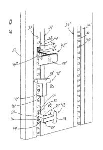
Fig 16 shows a perspective view of a piece of furniture 30 The piece of
furniture may
constitute a book case, a cabinet, a cupboard or the like. The piece of
furniture 30
comprises a plane wall element 32 extending in a longitudinal direction, which
typically
is being a vertical direction_ The plane wall element 32 may be positioned on
a solid
surface (not shown) or alternatively be mounted on a wall (not shown). The
plane wall
element 32 comprises a pair of countersunk track elements 34 and 34, which
extend
parallel in the vertical direction of the plane wall element 32 The track
element 34
comprises a bottom wall 36, which is recessed in relation to the surface of
the plane
wall element 32, The track element 34 further comprises two opposite front
flanges 38,
which are extending outwardly in relation to the bottom wall 36 and
subsequently
extend inwardly towards each other. The front flanges 38 each thus define an L
shape
and defining between them a channel 39 having a specific width between them
constituting and opening for accessing the bottom wall 36. The bottom wall 36
further
comprises a multitude of substantially rectangular indentations 40, which are
spaced
apart equidistantly a specific distance. The indentations 40 may optionally be
replaced
by apertures The track element should be made of a rigid material, typically a
metal
material and preferably either steel or aluminium
CA 02763841 2011-11-29
WO 2010/115967 PCT/EP2010/054668
14
The piece of furniture 30 further comprises fitting elements 42 The fitting
elements 42
are preferably made of the same material as the track elements, e g aluminium
or
steel. The fitting elements 42 comprise a main portion 44 constituting a
rectangular
body defining a pair of opposite parallel side surfaces 45 and 451 and a plane
rear
surface 46. The rear surface 46 is plane and oriented perpendicularly in
relation to the
side surfaces 45 451 which as well are both plane Both side surfaces 45 and
451 are
further connected to an extension part 48, which is positioned opposite the
rear
surface 46 The side surfaces 45 and 451 define a distance between them, which
is
equal or slightly smaller than the width of the channel 39 between the front
flanges 38
The rear surface 46 further comprise an arresting pin 50 protruding outwardly
in
relation to the rear surface The arresting pin has a substantially rectangular
shape
equal to or slightly smaller than the indentation 40 of the bottom wall 46 of
the track
element 34 for being able to fit within the indentation 40
The fitting element 42 further comprises a junction part 52 extending from the
main
portion 44 in a direction to the rear surface 44 and a side surface 45. The
junction part
52 is rounded and having a width equal to or slightly smaller than the width
of the
channel 39 of the track element 34 The junction part 52 is further connected
to a
transversal bar 54 having a length perpendicular to the side surface 45
exceeding the
specific width of the channel 39 between the front flanges 38, however not
exceeding
the width of the bottom wall 36 The thickness of the transversal bar 54 should
be
smaller than the specific width of the channel 39.. The transversal bar 54 may
be
optionally rounded
The fitting element 42 is being mounted and arrested to the track element 54
by
following a three-step operation The three step operation is described in fig
16 by a
first fitting element 42 defining a first position, the fitting element 42'
defining a second
position and the fitting element 4211 defining a third position of the three
step operation
The first step of the three-step operation, which is shown in relation to the
first position
of the fitting element 42, involves positioning the fitting element 42 in
front of the
channel 39 of the track element 34 so that the transversal bar 54 is oriented
having its
length parallel with the vertical direction of the channel 39 of the track
element 34. The
transversal 54 is then introduced into the channel 39 and accommodated in the
channel , the junction part 52 is positioned in the channel 39 between the
front flanges
38 and the remaining portion of the fitting element including the main portion
44 is
positioned in front of the front flanges 38
CA 02763841 2011-11-29
WO 2010/115967 PCT/EP2010/054668
In the second step, the fitting element 42 is rotated by 90 degrees around an
axis
defined by the junction part 52 in a direction as indicated in the figure by
arrow A, i.e
the extension part 48 is being rotated upwardly by 90 degrees while
maintaining the
5 transversal bar 54 within the channel for achieving the second position
as indicated by
the fitting elements 481 In the second position the rear surface 461 is
oriented in a
downwardly direction. The fitting element 421 is then subsequently rotated
around an
axis defined by the transversal bar 54 in a direction as indicated by the
arrow B such
that the rear surface 46 is juxtaposed the bottom wall 36 of the track element
34.. The
10 transversal bar 54 remains within the channel 39 for achieving a third
position
indicated by the fitting element 42"
In a third step, the fitting element 4211 is shifted vertically along the
direction of the track
element 34 by the user. When the user has found a suitable position among the
15 available positions defined by the multitude of indentations 40 of the
fitting element
42", the arresting pin 50 is caused to enter a single indentation 40 for the
fitting
element 42 and be arrested at the user-selected position When the arresting
pin 50
has been arrested within the single indentations 40, the fitting element 42 is
locked in
place and may withstand a downwardly oriented force which is applied to the
extension part 48 In the present embodiment, the cooperation between the
arresting
pin 50 and the indentation 40 will hold a downwardly force applied to the
extension
part 48 The arresting pin 50 is kept within the indentation 40 by the
cooperation
between the transversal bar 54 and the front flanges 38 counteracting the
rotation
momentum induced by a downwardly directed force on the extension part 48 and
preventing the arresting pin 50 from slipping out of the indentation 40
A single fitting element 42 may be used for accommodating e.g. a hinge for a
door or a
gate etc. Two opposing fitting elements mounted on two opposing track elements
34 of
two opposing wall elements 32 may be used to hold a horizontal wall element
(not
shown), which may constitute e.g. a shelf
The fitting element 42 may be removed by performing the three step operation
in
reverse order, i.e.. first rotating the fitting element 42 upwardly around the
transversal
bar, subsequently sideward around the junction part 52 and finally removing
the fitting
element 42 from the channel 39.
CA 02763841 2011-11-29
WO 2010/115967 PCT/EP2010/054668
16
In the below description of variants of elongated track elements and fitting
elements
and further fittings and connectors, components or elements serving the same
purpose as components or elements, respectively, described above with
reference to
the drawings' figures 1-16 however differing in the geometrical configuration
or shape,
the fittings, connectors etc. are designated the same reference numeral as
used
above, however, added a marking for indicating the geometrical difference.
In Figs. 17A and 17B, a further embodiment of the elongated track elements
described
above is shown designated the reference numeral 3411. The elongated track
element
3411 shown in Figs 17A and 17B basically serves the same function as described
above with reference to Fig. 16 and further includes as evident from Fig. 17B
rear side
corrugations for allowing the elongated track element to be fixated in a
countersunk
recess of a wall not shown in Figs.. 17A and 17B The elongated track element
3411
shown in Fig 17A and 17B further comprises the features described above with
reference to Fig. 16, such as the bottom wall 36 and the flanges 38 and the
indentations 40 No further description of these features or elements are
presented
here as reference is made to the above description referring to figure 16 In
Figs 17C-
17H the elongated track element 3411 is shown in elevational rear view,
elevational side
view, elevational front view, elevational side view, elevational end view and
elevational
end view, respectively.
In Fig.. 18, the fitting element 42 described above with reference to Fig 16
is shown in
greater detail and in Figs 18C-18H, the fitting element 42 is shown in top
elevational
view, side elevational view, bottom elevational view, side elevational view,
end
elevational view and front elevational view, respectively. The element is not
to be
described in greater detail here as reference is made to the above detailed
description
of the configuration and function of the fitting element referring to Fig. 16
In Figs 19A and 19B, a shelf brick is shown which shelf may be used as an
alternative
to the elongated track element 3411 shown in Fig 17A-17H, as the brick element
is
fitted into a circular recess of a plane wall element such as the plane wall
element 32
shown in Fig 16. The shelf brick element shown in Figs 19A and 19B is
designated
the reference numeral 60 and constitutes a basically circular cylindrical body
having a
facial cut-away front wall 62 and defines a bottom side shown in Fig. 19A and
a top
side shown in Fig 19B In the top side a substantially T-shaped recess 64 is
provided
having a configuration corresponding to the freely extending part 48 of the
fitting
CA 02763841 2011-11-29
WO 2010/115967 PCT/EP2010/054668
17
element 42 shown in Figs 18A-18H and further shown and described with
reference to
Fig. 16 Figs 19C-19F show a front elevational view, top elevational view, side
elevational view and a bottom elevational view, respectively, of the shelf
brick element
5
In Figs 20A and 20B, an alternative connector element is shown designated the
reference numeral 421 The connector element 421 shown in Figs 20A and 20B
constitutes an alternative to the fitting element 42 shown in Figs 16 and 18A-
18F as
the connector element is provided with an extension 66 as compared to the
fitting
10 element 42 which extension is provided with outwards protruding
connectors 68 for the
mounting of hinge or other component to be fixated relative to the piece of
furniture in
which the connector element 421 is fixated similar to the fixation described
above with
reference to Fig 16 of the fitting element 42
15 In Figs. 20C-20H, the connector element is shown
in side elevational view, rear
elevational view, side elevational view, front elevational view, bottom
elevational view
and top elevational view, respectively..
In Fig 21A and 21B, an alternative connector element 4211 is shown, which
element
20 constitutes a variant of the connector element 421 described above with
reference to
Figs 20A-20H as the connector element 4211 shown in Figs 21A and 21B is
provided
with a single outwards protruding connectors 68.
Similar to the views Figs 20C-20H, Figs 21C-21H illustrate the alternative
connector
25 element 4211 shown in Figs 21A and 21B in side elevational view, rear
elevational
view, side elevational view, front elevational view, bottom elevational view
and top
elevational view, respectively..
In Figs 22A and 22B a further variant of the fitting element 42 described
above with
30 reference to Figs. 16 and 18A-18H is shown which differs from the above-
described
fixation element 42 in that the element 42.111 shown in Figs 22A and 22B is
provided
with a sidewise eyelet extension 70 substituting the transversal extension
part 48 of
the fixation element 42 described above. The eyelet extension 70 may be used
for
fixating a screw, nail or similar element to a supporting horizontal surface
which is
35 fixated relative to a side panel by means of the connector element 42111
In Figs 22C-
22H, the connector element 42111 is shown in side elevational view, front
elevational
CA 02763841 2011-11-29
WO 2010/115967 PCT/EP2010/054668
18
view, side elevational view, rear elevational view, top devotional view and
bottom
elevational view, respectively..
In Fig. 23A and 23B, a further alternative connector element 421v is shown
constituting
a variant of the above-described connector elements 421 and 4211 shown in
Figs. 20A-
20H and 21A-21H, respectively, as the connector element 42v shown in Figs 23A
and
23B is provided with an extension 66 similar to the above-described extensions
66
and 661 of the connector elements 421 and 4211, respectively, which extension
66" is
provided with curved end face 69 serving as supporting face or a rest In Figs
23C-
23H, the connector element 421v is shown in side elevational view, front
elevational
view, side elevational view, rear elevational view, bottom elevational view
and top
devotional view, respectively.
In Figs 24A and 24B, a further connector element 42v is shown differing from
the
above-described connector elements 421 and 42" shown in Figs 20A-20H and Figs
21A-21H, respectively, in that the connectors 68 are substituted by a pair of
magnets
42 received within the recesses of the extension 661v of the connector element
42" In
Figs. 240-24H, the connector element 42' shown in Figs. 24A and 2413 is shown
in
side elevational view, rear elevational view, side elevational view, front
elevational
view, bottom elevational view and top elevational view, respectively.
In Figs. 25A and 25B, a further connector element 42v1 is shown differing from
the
above-described connector element 421 - 42" described above with reference to
Figs
18-24 in that the element is provided with a major transversal bar 74 serving
for the
support of a plate which may be supported on the top surface of the bar 74 or
alternatively fixated at the ends of the transversal bar 74 In Figs 25C-25H,
the
connector element 42v1is shown in side elevational view, bottom elevational
view, front
elevational view, top elevational view, side devotional view and rear
elevational view,
respectively.
In Figs, 26A and 268 a further connector element 42v" is shown having an
extension
66" similar to the extensions 66-66v of the connector embodiments shown in
Figs 20,
21 23 and 24 At the bottom end of the extension 66V, a clips is provided
designated
the reference numeral 76 servicing for receiving a side or rear panel of a
piece of
furniture In Figs. 26C-26H, the connector 42" shown in Figs. 26A and 26B is
shown
CA 02763841 2011-11-29
WO 2010/115967 PCT/EP2010/054668
19
in rear elevational view, side elevational view, front elevational view, side
elevational
view, bottom elevational view and top elevational view, respectively.
In Figs 27A and C, a further fitting element 601 is shown similar to the shelf
brick
element 60 described above with reference to Figs 19A-19F The fitting 601
serves to
corporate with the above connector element 42" for fixating the fitting 601 at
the
outmost ends of the transversal bar 74 of the connector element 42v1. The
fitting 601 is
basically an oval, cylindrical body having a central inwardly tapering
rectangular
aperture The aperture serves to allow a panel in which the fitting 601 is
mounted to be
cooperating with and fixated relative to the end part of the transversal bar
74 of the
connector element 42v1 In Figs 27C-27H, the fitting 601 is shown in front
elevational
view, side elevational view, rear elevational view, side elevational viewõ top
elevational view and bottom elevational view, respectively
Although the present invention has above been described with reference to
specific
preferred embodiment, it is evident to person skilled in the art, that
numerous
modifications may be incorporated in the above-described embodiment and
further,
alternative embodiments may be deduced in accordance with the teachings of the
present invention and the teachings is defined in the appending patent claims
25
CA 02763841 2011-11-29
WO 2010/115967 PCT/EP2010/054668
POINTS CHARACTERISING THE INVENTION.
1 An assembly system for furniture, the system comprising.
- an elongated track element which is attachable to a first furniture element
and which
5 defines a channel extending in an axial direction and
- a fitting element with a first locking portion,
the elongated track element and fitting element cooperating to define.
- an open mutual orientation, wherein the first locking portion is allowed
passage into
and out of the channel,
10 - a closed mutual orientation, wherein the first locking portion is
movable in the axial
direction within the channel, and
- a fixed mutual orientation, wherein the first locking portion is locked
immovably
relative to the elongated track element
15 2 An assembly system according to point 1, wherein the elongated track
element
comprises a flange portion defining an opening into the channel and allowing
passage
of the first locking portion into the channel in the open mutual orientation
and which
prevents movement of the first locking portion out of the channel in the
closed mutual
orientation
3, An assembly system according to points 1-2, wherein the fitting element
further
comprises a second locking portion adapted to retain a second furniture
element
4. An assembly system according to any of the preceding points, wherein the
fitting
element and elongated track element comprise locking features cooperating to
prevent
movement of the fitting element in the axial direction when the fitting
element and the
elongated track element define the fixed mutual orientation
5 An assembly system according to point 4, wherein the locking features
provide a
plurality of locking positions at the elongated track element along the axial
direction at
which locking positions movement of the fitting element Is prevented
6. An assembly system according to point 4 or 5, wherein the locking features
of the
fitting element comprise protrusions adapted to engage corresponding cavities
in the
channel to fixate the fitting element in the elongated track element
CA 02763841 2011-11-29
WO 2010/115967 PCT/EP2010/054668
21
7. An assembly system according to any of points 4-6, wherein the locking
features
comprise an indented surface of one of the fitting element and the elongated
track
element arranged to engage a projection or Indentation in the other one of the
fitting
element and elongated track element
8. An assembly system according to any of the preceding points, wherein the
channel
in a cross section perpendicular to the axial direction forms end portions on
opposite
side of an intermediate portion, the end portions extending towards an opening
into the
channel
9.. An assembly system according to point 8, wherein the channel in a cross
section
perpendicular to the axial direction forms an quadrangular shape with a front
wall, a
rear wall and two sidewalls, the opening being formed in the front wall
10 An assembly system according to point 9, wherein the front wall and rear
wall are
essentially parallel..
11 An assembly system according to point 9, wherein the sidewalls are
essentially
parallel
12 An assembly system according to point 9, wherein the front and rear walls
are
perpendicular to the sidewalls
13. An assembly system according to any of points 6-12, wherein the cavities
are
formed in the rear wall.
14.. An assembly system according to any of points 3-13, wherein the second
locking
portion is formed to engage a depression of the second furniture element,
15, An assembly system according to point 14, wherein the fitting element is
shaped to
reduce the distance between the first and second furniture elements when the
second
locking portion engages the depression
16 An assembly system according to any of point 1-13, wherein the second
locking
portion is connected to a hinge to support a door element
CA 02763841 2011-11-29
WO 2010/115967 PCT/EP2010/054668
22
17 A piece of furniture with at least a first furniture element and a second
furniture
element, the furniture elements being connected by an assembly system, said
assembly system comprising,
- an elongated track element attached to the first furniture element, which
elongated
track element defines a channel extending In an axial direction, and
- a fitting element with a first locking portion,
the elongated track element and fitting element cooperating to define.
- an open mutual orientation, wherein the first locking portion is allowed
passage into
and out of the channel,
- a closed mutual orientation, wherein the first locking portion is movable In
the axial
direction within the channel, and
- a fixed mutual orientation, wherein the first locking portion is locked
immovably
relative to the elongated track element
18. An assembly for making furniture, the assembly comprising
- at least one furniture element comprising an elongated track element which
defines a
channel extending in an axial direction,
- at least one fitting element with a first locking portion, and
- at least one additional furniture element to be joined to the other
furniture element via
the fitting element,
the elongated track element and fitting element cooperating to define:
- an open mutual orientation, wherein the first locking portion is allowed
passage into
and out of the channel,
- a dosed mutual orientation, wherein the first locking portion is movable in
the axial
direction within the channel, and
- a fixed mutual orientation, wherein the first locking portion is locked
immovably
relative to the elongated track element
19 A method of assembling a piece of furniture from at least two furniture
elements,
one of which being provided with an elongated track element which defines a
channel
extending in the axial direction and the other furniture element being
provided with a
feature which cooperate with a fitting element with a first locking portion,
the elongated track element and fitting element cooperating to define.
- an open mutual orientation, wherein the first locking portion Is allowed
passage into
and out of the channel,
- a closed mutual orientation, wherein the first locking portion Is movable In
the axial
CA 02763841 2011-11-29
WO 2010/115967 PCT/EP2010/054668
23
direction within the channel, and
- a fixed mutual orientation, wherein the first locking portion is locked
immovably
relative to the elongated track element,
the method comprising the steps of
- inserting the first locking portion into the channel of the elongated track
element,
- reorienting the fitting element in the channel, and
- attaching the other furniture element to the fitting element