Note: Descriptions are shown in the official language in which they were submitted.
CA 02763995 2012-01-10
Attorney Docket No. 010121-8282-US00
GAS-FIRED WATER HEATER WITH AN EXHAUST ASSEMBLY
BACKGROUND
[0001] The present invention relates to water heaters, and more
particularly to gas-fired
water heaters with exhaust assemblies.
[0002] Typical gas-fired water heaters produce exhaust gases or products
of combustion
that must be exhausted outside of the residence or other building in which the
water heater is
installed. An exhaust assembly, blower, or fan moves the exhaust gases
generated by the water
heater from the water heater to the atmosphere outside the building.
SUMMARY
[0003] The present invention provides, in one aspect, an exhaust assembly
for use with a
gas-fired water heater. The exhaust assembly includes a hood for receiving
exhaust gas from the
gas-fired water heater, a housing, and a fan positioned in the housing to move
exhaust gas from
the hood out of the exhaust outlet. The hood includes a first hood mounting
location and a
second hood mounting location. The housing includes an exhaust outlet and a
housing mounting
location. In a first configuration, the exhaust outlet faces a first direction
and the housing
mounting location is aligned with and secured at the first hood mounting
location. In a second
configuration, the exhaust outlet faces a second direction different than the
first direction and the
housing mounting location is aligned with and secured at the second hood
mounting location.
[0004] The present invention provides, in another aspect, an exhaust
assembly for use
with a gas-fired water heater. The exhaust assembly includes a hood for
receiving exhaust gas
from the gas-fired water heater, a back plate coupled to the hood, a housing,
multiple tabs, and a
fan positioned in the housing to move exhaust gas from the hood out of the
exhaust outlet. The
hood includes a first hood mounting location and a second hood mounting
location. The back
plate includes a rearwardly extending cylindrical rim with a locking groove
formed in the outer
surface of the rim. The housing includes an exhaust outlet, a housing mounting
location, and a
cylindrical collar with multiple slots through the collar. The rim is
positioned within the collar.
Each of the tabs is coupled to the housing and extends through a corresponding
slot and into the
1
CA 02763995 2017-01-20
67363-1739
locking groove, thereby rotatably coupling the housing to the hood. In a first
configuration,
the exhaust outlet faces a first direction and the housing mounting location
is aligned with and
secured at the first hood mounting location. In a second configuration, the
exhaust outlet faces
a second direction different than the first direction and the housing mounting
location is
aligned with and secured at the second hood mounting location.
[0005] The present invention provides, in another aspect, a gas-fired
water heater. The
gas-fired water heater includes a storage tank, a combustion chamber, a burner
for producing
products of combustion, the burner positioned in the combustion chamber, a
flue extending
from the combustion chamber through the storage tank, and an exhaust assembly
positioned
above the flue. The exhaust assembly includes a hood for receiving the
products of
combustion from the gas-fired water heater, a housing, and a fan positioned in
the housing to
move the products of combustion from the hood out of the exhaust outlet. The
hood includes a
first hood mounting location and a second hood mounting location. The housing
includes an
exhaust outlet and a housing mounting location. In a first configuration, the
exhaust outlet
faces a first direction and the housing mounting location is aligned with and
secured at the
first hood mounting location. In a second configuration, the exhaust outlet
faces a second
direction different than the first direction and the housing mounting location
is aligned with
and secured at the second hood mounting location.
[0005a] The present invention provides, in another aspect an exhaust
assembly for use
with a gas-fired water heater, the exhaust assembly comprising: a hood for
receiving exhaust
gas from the gas-fired water heater, the hood including a first hood mounting
location and a
second hood mounting location; a back plate coupled to the hood, the back
plate including a
rearwardly extending cylindrical rim with a locking groove formed in the outer
surface of the
rim, the cylindrical rim including a center axis; a housing including an
exhaust outlet, a
housing mounting location, and a cylindrical collar with a plurality of slots
through the collar,
the rim positioned within the collar; a plurality of tabs separate from the
housing, hood, and
backplate, each tab inserted through the slots in the collar and into the
locking groove and
fastened to the housing, thereby rotatably coupling the housing to the hood
with the tabs free
to slide within the locking groove so that the housing is rotatable about the
center axis of the
cylindrical rim; and a fan positioned in the housing to move exhaust gas from
the hood out of
2
CA 02763995 2017-01-20
=
67363-1739
the exhaust outlet; wherein in a first configuration, the exhaust outlet faces
a first direction
and the housing mounting location is aligned with and secured at the first
hood mounting
location; and wherein in a second configuration, the exhaust outlet faces a
second direction
different than the first direction and the housing mounting location is
aligned with and secured
at the second hood mounting location.
[0006] Other features and aspects of the invention will become
apparent by
consideration of the following detailed description and accompanying drawings.
BRIEF DESCRIPTION OF THE DRAWINGS
[0007] FIG. 1 is a front view of a water heater including an exhaust
assembly.
[0008] FIG. 2 is a perspective view of the exhaust assembly of FIG. 1
in a first
configuration.
[0009] FIG. 3 is an exploded view of the exhaust assembly of FIG. 1.
[0010] FIG. 4 is a perspective view of a hood of the exhaust assembly
of FIG. 1.
2a
CA 02763995 2012-01-10
Attorney Docket No. 010121-8282-US00
LOOM FIG. 5 is a perspective view of a back plate of the exhaust
assembly of FIG. 1.
[0012] FIG. 6 is a front perspective view of a blower housing of the
exhaust assembly of
FIG. 1.
[0013] FIG. 7 is a rear perspective view of the blower housing of FIG. 6.
[0014] FIG. 8 is a section view through a portion of the exhaust assembly
of FIG. 1.
[0015] FIG. 9 is a rear perspective view of the blower housing of FIG. 6.
[0016] FIG. 10 is a perspective view of the exhaust assembly of FIG. 1 in
a second
configuration.
[0017] FIG. 11 is a perspective view of the exhaust assembly of FIG. 1 in
a third
configuration.
[0018] FIG. 12 is a perspective view of a second embodiment of an exhaust
assembly.
[0019] FIG. 13 is an exploded view of the exhaust assembly of FIG. 12.
[0020] FIG. 14 is a perspective view of a third embodiment of an exhaust
assembly.
[0021] FIG. 15 is an exploded view of the exhaust assembly of FIG. 14.
[0022] Before any embodiments of the invention are explained in detail,
it is to be
understood that the invention is not limited in its application to the details
of construction and the
arrangement of components set forth in the following description or
illustrated in the following
drawings. The invention is capable of other embodiments and of being practiced
or of being
carried out in various ways. Also, it is to be understood that the phraseology
and terminology
used herein is for the purpose of description and should not be regarded as
limiting.
DETAILED DESCRIPTION
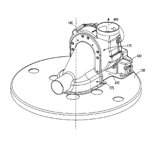
[0023] FIG. 1 illustrates a gas-fired water heater 100. The water heater
100 includes a
water storage tank 105 and a combustion chamber 110 positioned below the
storage tank 105. A
3
CA 02763995 2012-01-10
Attorney Docket No. 010121-8282-US00
gas burner 115 is positioned in the combustion chamber 110. A flammable gas is
provided to the
gas burner 115 by a gas inlet or manifold 120 connected to a gas valve 125.
The gas valve 125 is
also connected to a gas supply. The combustion chamber 110 communicates with
an air supply,
for example, the atmosphere around the water heater 100. A jacket 130
including a cover 135
surrounds the storage tank 105 and combustion chamber 110. Foam insulation is
provided
between the storage tank 105 and jacket 130. A flue 140 extends from the
combustion chamber
110, through the storage tank 105, and through the cover 135. The flue 140
includes a
longitudinal axis 145. The products of combustion or exhaust gases created by
the gas burner
115 flow through the flue 140 to heat the water stored in the storage tank
105. A cold water inlet
pipe 150 is connected to a dip tube 155 to supply cold water to the storage
tank 105. A hot water
supply pipe 160 is connected to the storage tank 105 to supply hot water to an
end-use location,
for example, a faucet. An exhaust assembly 165 is coupled to the cover 135 and
positioned
above the flue 140. The exhaust assembly 165 receives the exhaust gas exiting
the flue 140. The
structure of the gas-fired water heater 100 other than the exhaust assembly
165 is typical of
known gas-fired water heaters. The exhaust assembly 165 could also be used
with other known
gas-fired water heaters, including instantaneous or tankless water heaters or
tank-tankless water
heaters. Directional language refers to the exhaust assembly 165 as installed
for normal,
intended use with a gas-fired water heater 100.
[0024]
As shown in FIGS. 2 and 3, the exhaust assembly 165 includes a hood 170, a
back
plate 172, a blower housing 175, a fan, blower, or impeller 180, and a motor
185. As shown in
FIG. 4, the hood 170 includes a chamber 190 with an open bottom portion 195
and an open rear
portion 200. The open bottom portion 195 is open to the flue 140 so the
chamber 190 receives
exhaust gas from the flue 140. A cover mounting flange 205 extends from the
periphery of the
bottom portion 195 for securing the hood 170 to the cover 135. The cover
mounting flange 205
includes cut-outs or indentations 210 as necessary to accommodate the cold
water inlet pipe 150
and the hot water supply pipe 160. The indentations 210 allow the hood 170 to
be positioned
between the cold water inlet pipe 150 and the hot water supply pipe 160. An
air inlet 215 is
connected to the chamber 190. Ambient dilution air is drawn through the air
inlet 215 into the
chamber 190. The dilution air mixes with the exhaust gas in the chamber 190,
thereby reducing
the concentration of undesirable chemicals formed during the combustion
process and lowering
4
CA 02763995 2012-01-10
Attorney Docket No. 010121-8282-US00
the temperature of the exhaust gas before the mixture enters the blower
housing 175. A housing
mounting flange 220 extends from the periphery of the rear portion 200. The
housing mounting
flange 220 includes three hood mounting locations 225, 230, and 235. The first
hood mounting
location 225 is spaced ninety degrees from the second hood mounting location
230 and one
hundred eighty degrees from the third hood mounting location 235. As shown,
each hood
mounting location 225, 230, and 235 includes a pair of apertures, holes, or
openings 240 through
the housing mounting flange 220.
100251 As shown in FIG. 3, the back plate 172 is secured to the hood 170
to partially
cover the open rear portion 200. As shown in FIG. 5, the back plate 172
includes a wall 250, a
circular opening 255 through the wall 250, and a rim 260 surrounding the
opening 255 and
extending rearwardly from the wall 250. The rim 260 is cylindrical and coaxial
with the opening
255. As best shown in FIG. 8, the rim 260 includes a protrusion 265 where the
outer diameter of
the rim 260 decreases from a wide portion 270 to a narrow portion 275. The rim
260 also
includes a locking groove 280 formed in the outer surface of the rim 260 about
the circumference
of the rim 260. Additionally, two seal grooves 285 are formed in the outer
surface of the rim 260
about the circumference of the rim 260. An o-ring or seal 290 is positioned in
one or both of the
seal grooves. The o-ring 290 is compressed between the back plate 172 and the
blower housing
175 to provide a substantially air-tight seal between the back plate 172 and
the blower housing
175. As shown in FIG. 3, a gasket or seal 295 is positioned between the back
plate 172 and the
hood 170. The gasket 295 is compressed between the back plate 172 and the hood
170 to
provide a substantially air-tight seal between the back plate 172 and the hood
170. In some
embodiments, the back plate 172 is an integral component of the hood 170.
[0026] As shown in FIGS. 6 and 7, the blower housing 175 includes a front
wall 300, an
outer wall 305, an open rear portion 310, and an exhaust outlet 315. An
opening 320 is formed
through the front wall 300. A collar 325 surrounds the opening and extends
rearwardly from the
front wall 300. The collar 325 is cylindrical and coaxial with the opening
320. As best shown in
FIG. 8, the collar 325 includes a stop 330 where the inner diameter of the
collar 325 decreases
from a wide portion 335 to a narrow portion 340. As shown in FIGS. 6 and 7,
four slots or
openings 345 extend through the collar 325. The slots 345 are positioned
ninety degrees apart
from one another about the center axis of the collar 325 and opening 320. Four
tab mounting
CA 02763995 2012-01-10
Attorney Docket No. 010121-8282-US00
locations 350 are positioned radially outwardly of the slots 345 on the front
wall 300. Each tab
mounting location 350 includes a pair of bosses 355 and a pair of openings
360, each opening
360 extending through a boss 355 and the front wall 300. In some embodiments,
the openings
360 are threaded. In other embodiments, a threaded insert is positioned in
each opening 360. A
housing mounting location 365 is positioned radially outwardly from one of the
tab mounting
locations 350 on the front wall 300. The housing mounting location 365
includes a pair of
bosses 370 and a pair of openings 375, each opening extending into a boss 370.
In some
embodiments, the openings 375 are threaded. In other embodiments, each boss
370 includes a
threaded insert positioned in the opening 375 extending into the boss 370.
[0027] The outer wall 305 is generally cylindrical and the exhaust outlet
315 extends
tangentially from the outer wall 305. Exhaust gases exit the blower housing
175 through the
opening 380 along an outlet axis 385. The exhaust outlet 315 faces in the
direction of the
exhaust gases exiting the blower housing 175 along the outlet axis 385.
[0028] As shown in FIG. 8, the blower housing 175 is coupled to the back
plate 172 so
that the collar 325 receives the rim 260 and the collar 325 and the rim 260
are coaxial. The
protrusion 265 abuts the stop 330 to limit the axial insertion of the rim 260
into the collar 325
and to align the slots 345 with the locking groove 280. A tab 390 is inserted
through each of the
slots 345 so that a lower portion of the tab 390 is positioned in the locking
groove 280. As
shown in FIG. 9, each tab 390 includes a pair of openings 395 that are aligned
with the openings
360 of a tab mounting location 350 when the tab 390 is inserted into a slot
345. A fastener is
inserted through each opening 395 and into a corresponding opening 360 to
secure each tab 390
to the blower housing 175 at a tab mounting location 350. The fasteners can
be, for example, a
threaded bolt or a sheet-metal screw. After the tabs 390 are secured to the
blower housing 175,
the tabs 390 are free to slide within the locking groove 280 so that the
blower housing 175 is
rotatable about the center axis of the rim 260 and cannot be non-destructively
uncoupled from
the hood 170 without unsecuring the tabs from the blower housing 175.
[0029] As shown in FIGS. 2, 10, and 11, the blower housing 175 can be
secured in three
positions relative to the hood 170. In a first configuration, the exhaust
outlet 315 faces in a first
direction 400 that is angled ninety degrees from the longitudinal axis 145 of
the flue 140 and the
6
CA 02763995 2012-01-10
Attorney Docket No. 010121-8282-US00
housing mounting location 365 is aligned with the first hood mounting location
225. The
housing mounting location 365 is secured at the first hood mounting location
225. In a second
configuration, the exhaust outlet 315 faces in a second direction 405 that is
angled ninety degrees
from the first direction 400 (parallel to the longitudinal axis 145 of the
flue 140) and the housing
mounting location 365 is aligned with the second hood mounting location 230.
The housing
mounting location 365 is secured at the second hood mounting location 230. In
a third
configuration, the exhaust outlet 315 faces in a third direction 410 that is
angled one hundred
eighty degrees from the first direction 400 and the housing mounting location
365 is aligned with
the third hood mounting location 235. The housing mounting location 365 is
secured at the third
hood mounting location 235. The blower housing 175 is rotated or pivoted about
an axis
perpendicular to the longitudinal axis 145. The directions 400, 405, and 410
are located in a
plane that is parallel to the longitudinal axis 145. The housing mounting
location 365 is secured
to one of the hood mounting locations 225, 230, and 235 by inserting a
fastener through each of
the openings 240 and into a corresponding opening 375. The fasteners can be,
for example, a
threaded bolt or a sheet-metal screw. The exhaust assembly 165 allows the
installer to rotate the
blower housing 175 between the three configurations without having to
partially disassemble the
exhaust assembly 165. The tabs 390 ensure that the blower housing 175 remains
coupled to the
back plate 172 even when the housing mounting location 365 is not secured at a
hood mounting
location 225, 230, and 235. In some embodiments, the exhaust assembly 165
includes more or
fewer configurations as described above. More configurations are added by
increasing the
number of hood mounting locations. Decreasing the number of hood mounting
locations reduces
the number of configurations.
100301 As shown in FIG. 3, the fan 180 is positioned within the blower
housing 175. A
cover 415 is secured to the blower housing 175 to cover the open rear portion
310. The motor
185 is secured to the cover 415 by a motor mount 420. A motor shaft 425
extends from the
motor 185 through the cover 415 and is connected to the fan 180. As the motor
185 shaft rotates,
the fan 180 also rotates to move the exhaust gas from the hood 170 out of the
exhaust outlet 315.
A control unit 430 is mounted to a base plate 435 and electrically connected
to the motor 185.
The control unit 430 includes a power supply, a controller, and other
components necessary to
power and control the motor 185 and the exhaust assembly 165. The base plate
435 includes a
7
CA 02763995 2012-01-10
Attorney Docket No. 010121-8282-US00
back plate bracket 440 that is secured to the back plate 172 and positioned
between the back
plate 172 and the hood 170.
[0031] FIGS. 12 and 13 illustrate an exhaust assembly 565 similar to the
exhaust
assembly 165. Components similar to those of exhaust assembly 165 described
above are
numbered in a similar fashion plus four hundred. Some of the differences
between the exhaust
assembly 565 and the exhaust assembly 165 are described below.
[0032] The hood 570 includes four hood mounting locations 445, 450, 455,
and 460.
Each of the hood mounting locations 445, 450, 455, and 460 includes an
opening, aperture, or
hole 465 through the housing mounting flange 620. Each of the four hood
mounting locations
445, 450, 455, and 460 is positioned at a corner of a quadrilateral, for
example, a square or
rectangle. The exhaust assembly 565 does not include a back plate 172.
Instead, the back plate
bracket 840 of the base plate 835 is coupled to the hood 570 and partially
covers the open rear
portion 600. The back plate bracket 840 includes an opening 470. The blower
housing 575 does
not include a collar 725. The front wall 700 of the blower housing 575
includes four housing
mounting locations 475, 480, 485, and 490. Each of the housing mounting
locations 475, 480,
485, and 490 includes a boss 495 and an opening 500 extending into the boss
495. In some
embodiments, the openings 500 are threaded. In other embodiments, a threaded
insert is
positioned in each opening 500 extending into a boss 495. Each of the four
housing mounting
locations 475, 480, 485, and 490 is positioned at a corner of a quadrilateral,
for example, a
square or rectangle. The size and shape of the quadrilateral formed by the
four housing
mounting location 475, 480, 485, and 490 is substantially identical to the
size and shape of the
quadrilateral formed by the four hood mounting locations 445, 450, 455, and
460.
[0033] The blower housing 575 is secured to the hood 570 by inserting a
fastener through
each of the openings 465 and into a corresponding opening 500. In a first
configuration, the
exhaust outlet 715 faces in the first direction 400 that is angled ninety
degrees from the
longitudinal axis 145 of the flue 140 and the first housing mounting location
475 is aligned with
the first hood mounting location 445. In a second configuration, the exhaust
outlet 715 faces in
the second direction 405 that is angled ninety degrees from the first
direction 400 (parallel to the
longitudinal axis 145 of the flue 140) and the first housing mounting location
475 is aligned with
8
CA 02763995 2012-01-10
Attorney Docket No. 010121-8282-US00
the second hood mounting location 450. In a third configuration, the exhaust
outlet 715 faces in
the third direction 410 that is angled one hundred eighty degrees from the
first direction 400 and
the first housing mounting location 475 is aligned with the third hood
mounting location 455.
The opening 470 through the back plate bracket 840 is coaxial with the opening
720 through the
front wall 700 of the blower housing 575 when the blower housing 575 is
secured to the hood
570.
[0034] FIGS. 14 and 15 illustrate an exhaust assembly 965 similar to the
exhaust
assembly 565. Components similar to those of exhaust assembly 565 described
above are
numbered in a similar fashion plus four hundred. Some of the differences
between the exhaust
assembly 965 and the exhaust assembly 565 are described below.
[0035] The air inlet 1015 is a grate formed by a series of slots or
elongated openings 505
rather than a tube. A ring-shaped plate 510 is positioned between the blower
housing 975 and
the back plate bracket 1240. The plate 510 includes a central opening 515 that
is smaller in
diameter than the opening 870 through the back plate bracket 1240.
Alternatively, the plate 510
is positioned between the hood 970 and the back plate bracket 1240. The motor
mount 1220
secures the motor 985 to the blower housing 975 and also serves to cover the
open rear portion
1110 of the blower housing 575. The opening 1180 in the exhaust outlet 1115 is
square. A
transition collar 520 connected to the exhaust outlet 1115 changes the cross
section of the
exhaust gas flow path from a square to a circle.
[0036] In a first configuration, the exhaust outlet 1115 faces in the
first direction 400 that
is angled ninety degrees from the longitudinal axis 145 of the flue 140 and
the first housing
mounting location 875 is aligned with the first hood mounting location 845. In
a second
=
configuration, the exhaust outlet 1115 faces in the second direction 405 that
is angled ninety
degrees from the first direction 400 (parallel to the longitudinal axis 145 of
the flue 140) and the
first housing mounting location 875 is aligned with the second hood mounting
location 850. In a
third configuration, the exhaust outlet 1115 faces in the third direction 410
that is angled one
hundred eighty degrees from the first direction 400 and the first housing
mounting location 875
is aligned with the third hood mounting location 855. The opening 515 through
the plate 510,
the opening 870 through the back plate bracket 1240, and the opening 1120
through the front
9
CA 02763995 2012-01-10
Attorney Docket No. 010121-8282-US00
wall 1100 of the blower housing 975 are all coaxial when the blower housing
975 is secured to
the hood 970.
[0037] The three configurations of the exhaust assemblies 165, 565, and
965 allow an
installer to configure an exhaust assembly 165, 565, and 965 to best meet the
spacing limitations
of the installation location of the water heater 100. Known exhaust assemblies
only allow for an
upward orientation of an exhaust outlet when the exhaust assembly is installed
for use in the
intended manner. This can complicate or limit the installation of an exhaust
assembly if the
installation location has a low clearance above the water heater, if the
installation location is
crowded with other appliances or ductwork, or if the installation location
includes other
obstacles. By allowing the exhaust outlet 315, 715, and 1115 to be oriented in
three different
directions 400, 405, and 410, each exhaust assembly 165, 565, 965 allows the
installer to select
the best configuration for use with a specific installation location. Once the
installer has chosen
one of the three configurations, the exhaust outlet 315, 715, and 1115 can be
connected to an
exhaust duct that connects the exhaust assembly 165, 565, and 965 to the
atmosphere outside the
building. Additionally, selecting the best configuration for use with a
specific installation
location can eliminate an elbow in the exhaust duct, thereby reducing the
length of duct needed
between the water heater and the outside of the building.
[0038] A hood mounting location is the location on the hood with which a
housing
location is aligned in a specific configuration of the exhaust assembly and to
which the housing
mounting location is secured. The hood mounting locations and housing mounting
locations
described above are illustrative of a variety of possible hood mounting
location and housing
mounting locations. In some embodiments, more or fewer openings are provided
at each hood
mounting location and housing mounting location. In other embodiments, a hood
mounting
location is a specific portion of the housing mounting flange and the housing
mounting location
is a specific portion of the front wall that are aligned and secured together
by a fastener
including, for example, a self-tapping fastener, an adhesive, a clip, or a
clamp.
[0039] Various features of the invention are set forth in the following
claims.