Note: Descriptions are shown in the official language in which they were submitted.
CA 02764031 2011-11-30
WO 2010/144083 PCT/US2009/046852
METHOD AND APPARATUS FOR COUPLING A CASE TO A VIBRATING
FLOW METER
TECHNICAL FIELD
The present invention relates to, vibrating flow meters, and more
particularly, to
a method and apparatus for coupling a case to a vibrating flow meter.
BACKGROUND OF THE INVENTION
Vibrating flow meters such as, for example, densitometers and Coriolis flow
meters are used for measuring a characteristic of flowing substances, such as,
for
example, density, mass flow rate, volume flow rate, totalized mass flow,
temperature,
and other information. Vibrating flow meters include one or more conduits,
which may
have a variety of shapes, such as, for example, straight, U-shaped, or
irregular
configurations.
The one or more conduits have a set of natural vibration modes, including, for
example, simple bending, torsional, radial, and coupled modes. The one or more
conduits are vibrated by at least one driver at a resonance frequency in one
of these
modes for purposes of determining a characteristic of the flowing substance.
One or
more meter electronics transmit a driver signal to the at least one driver,
which is
typically a magnet/coil combination, with the magnet typically being affixed
to the
conduit and the coil being affixed to a mounting structure or to another
conduit. The
driver signal causes the driver to vibrate the one or more conduits at the
driver
frequency in the driver mode. For example, the driver signal may be a periodic
electrical current transmitted to the coil.
At least one pick-off detects the motion of the conduit(s) and generates a
sinusoidal pick-off signal representative of the motion of the vibrating
conduit(s). The
pick-off is typically a magnet/coil combination, with the magnet typically
being affixed
to one conduit and the coil being affixed to a mounting structure or to
another conduit.
The pick-off signal is transmitted to the one or more electronics; and
according to well
known principals the pick-off signal may be used by the one or more
electronics to
determine a characteristic of the flowing substance or adjust the driver
signal, if
necessary.
1
CA 02764031 2011-11-30
WO 2010/144083 PCT/US2009/046852
Typically, vibrating flow meters are provided with two vibrating conduits that
vibrate in opposition to each other in order to create an inherently balanced
system. As
a result, the vibrations from each conduit cancel each other out in a manner
that prevents
vibration or torque forces from being transmitted to any connecting
structures.
Likewise, when two vibrating conduits are used, vibrations of the mounting
structure are
canceled in the flow meter because the pick-offs generally measure only
relative motion
between the flow tubes, and externally induced vibrations tend to vibrate both
tubes
equally. There are, however, certain applications where dual conduits are
undesirable,
for example, due to problems with pressure drops or clogging. In such
situations a
single conduit system may be desirable.
However desirous a single conduit system may be, single conduit systems
present inherent imbalance problems. Attempts at solving this problem have
involved
using a balancing structure, for example, a dummy tube or a balance bar, and
using the
motion of the balancing structure to balance out the system. Since, however,
the overall
mass of the tube, including the fluid within the tube, changes as the density
of the fluid
within the tube changes, these techniques by themselves have received limited
success
at eliminating imbalance problems.
FIG. 1 depicts a single conduit type vibrating flow meter according to the
prior
art. As shown, the flow meter includes a case 106 enclosing a balance bar 102.
The
balance bar 102 is cylindrical and encloses conduit 101. Conduit 101 has
active portion
109 and inactive portions 110 and 110', which are defined by the connecting
rings 103,
104 of the balance bar 102. The inactive portions 110, 110' extend beyond end
elements 107, 108 of the case 106 to flanges (not shown). Conduit 101 has an
input end
111 connected to an opening in case end 107 and an output end 112 connected to
an
opening in the case end 108.
In operation, conduit 101 and balance bar 102 are vibrated in phase opposition
by
a driver D. With substance flowing, the vibration of conduit 101 in this
example
induces a Coriolis response in conduit 101 that is detected by pick-off
sensors LPO,
RPO. The phase displacement between the pick-off sensors represents
information
pertaining to the flowing substance. The signal output of the velocity sensors
is applied
to meter electronics circuitry 125 via leads 122, 124 that processes the
signals to derive
2
CA 02764031 2011-11-30
WO 2010/144083 PCT/US2009/046852
the desired information pertaining to the flowing substance, such as for
example a mass
flow rate, a density, a viscosity, etc.
It is necessary that a vibrating flow meter provide accurate information over
a
wide range of operating conditions including substances of different density,
temperature, and viscosity. In order to achieve this, it is desirable that the
flow meter
operate stably over a range of conditions. In order to achieve this stability,
it is
desirable for the flow meter vibrations to be isolated to the active conduit
portion and
balance system, because vibrations external to the vibratory system, whether
induced by
the vibrations of the flow meter or from another source, such as a pump,
imposes
additional accelerations on the flowing substance besides the Coriolis
acceleration used
to determine the fluid characteristics of the flowing substance. External
vibration also
repositions the nodes (area experiencing no motion) defining the active length
of the
conduit. This effect is difficult to compensate for and is subject to
unknowable
parameters such as the rigidity of the structure to which the meter is
connected.
Accordingly, undesired vibrations impede the ability of the flow meter to
provide
accurate output information regarding the flowing substance.
Prior art attempts at solving imbalance problems that arise due to changes in
the
density of the fluid involve adjusting the ratio of the vibration amplitude of
the conduit
relative to the vibration amplitude of the counterbalance structure. In
balancing a
structure, momentum is what is being balanced. Momentum is the product of mass
and
velocity, and velocity is proportional to vibration amplitude. Therefore,
altering the
vibration amplitude ratio alters meter balance. If, for example, the mass of a
conduit
(including the fluid located inside) and the mass of the counterbalance
structure were
initially equal and then the mass of the conduit were doubled (for example, as
a result of
a density increase in the fluid within the conduit), then reducing the
amplitude of the
conduit by half would restore balance to the conduit/counterbalance system. In
practice,
the combined amplitude of both the counterbalance structure and the conduit
can be
controlled by meter electronics. Accordingly, the conduit amplitude may be
reduced to
a lesser extent and the balance structure amplitude may be increased to some
extent until
in the above example, the ratio of the counterbalance amplitude relative to
the conduit
amplitude is 2:1.
3
CA 02764031 2011-11-30
WO 2010/144083 PCT/US2009/046852
The traditional method of adjusting the amplitude ratio as used in the prior
art is
to isolate the vibrating structure with a very soft (spring rate) mount. The
idea is that a
vibrating structure isolated in space is always balanced. For example if a
spring joins
two equal masses in space, such that when set vibrating out of phase with each
other, the
masses vibrate with equal amplitude and the spring has a motionless node half
way
between the masses. If one mass were to be increased and the masses were again
set
vibrating, the vibration amplitude of the increased mass would automatically
decrease,
and the vibration amplitude of the other mass would automatically increase to
keep the
momentum balanced. However, as a consequence, the new position of the node on
the
spring would relocate closer to the larger mass. The vibrating structure of a
vibrating
flow meter is similar, and node relocation is a problem.
Prior art flow meter designs that utilize self-balancing single tube meters
are
similar to a tuning fork wherein one tine is the active section of the flow
tube, the other
tine is the balance structure, and the handle is the inactive sections of the
flow tube
joining the active structure to the case. In this configuration, adding mass
to one tine of
the tuning fork decreases its amplitude and increases the amplitude of the
other. The
node, formerly at the junction of the two tines and the handle, relocates up
the tine with
the increased mass. The result is that the handle vibrates with the low-mass
tine. If the
vibrating handle is rigidly clamped, the vibration frequency rises, whereas if
it is loosely
clamped the frequency drops. This is a problem with flowmeters.
For the flow meter of FIG. 1, the vibrating system includes balance bar 102
and
active conduit portion 109 which are vibrated in phase opposition. The ends of
balance
bar 102 and the conduit 101 are coupled by connecting rings 103, 104. Inactive
tube
portions 110, 110' extend unsupported from the connecting rings 103, 104 to
the case
ends 107, 108. These inactive tube portions correspond to the tuning fork
handle. They
are necessary and they are unsupported because they are the soft mounts that
enable the
amplitude change with density. However, they vibrate like the tuning fork
handle when
the density of the fluid is changed. This is undesirable since the vibration
may cause the
vibration of the case 103 and flanges 106. Because the vibration amplitude of
the case
103 and flanges 106 is dependent upon the stiffness of the structure to which
the meter
is mounted, error of unknown magnitude can be induced in the flow measurement.
4
CA 02764031 2011-11-30
WO 2010/144083 PCT/US2009/046852
Adjusting the amplitude ratio in traditional method has an additional drawback
in
prior art meters in that it results in the repositioning of the motionless
nodes that reside
along the axis of the vibrating structure. The area between the nodes defines
the active
length of the conduit. The active length affects the measurement sensitivity.
If the
nodes relocate outwardly towards the case ends, the active length increases.
The
formerly inactive tube sections bend as a part of the vibration and that
bending motion
imparts Coriolis acceleration to the fluid. The additional Coriolis
acceleration either
adds to or subtracts from the sensitivity of the flow meter. Because the
rigidity with
which the meter is attached to the pipeline affects the amount of the
additional Coriolis
acceleration, there is no way to compensate for the relocation of the nodes.
This
relocation of the nodes further degrades the measurement accuracy.
There is however, one form of node relocation that does not change the meter
sensitivity. If the inactive portions of the flow tube are constrained to
rotation about
their axes, the nodes can move up and down the axes without changing the
Coriolis
acceleration of the fluid. This is because the so-called inactive tube portion
has to bend
in order to create a Coriolis acceleration in the fluid. No tube bending means
no
sensitivity change despite node relocation. Until now, however, this principle
has not
been used in Coriolis flow meters. Therefore, there is a need in the art for a
system that
can couple the flow tube to its case in such a manner that the tube is left
free to rotate
about its axis, but is substantially prevented from changing the active tube
length. The
present invention overcomes this and other problems and an advance in the art
is
achieved.
SUMMARY OF THE INVENTION
A vibrating flow meter is provided according to an embodiment of the
invention.
The vibrating flow meter comprises a flow conduit. The flow conduit includes a
first
end portion and a second end portion. The vibrating flow meter also includes a
case
surrounding at least a portion of the flow conduit. The vibrating flow meter
comprises a
first case connect. The first case connect includes a first portion coupled to
the first end
portion of the flow conduit. The first case connect also includes one or more
deformable members that extend radially from the first portion and are coupled
to the
case such that the first end portion can rotate about a conduit axis.
5
CA 02764031 2011-11-30
WO 2010/144083 PCT/US2009/046852
A case connect for a vibrating flow meter is provided according to an
embodiment of the invention. The case connect comprises a first portion
adapted to
couple to at least a portion of a flow conduit. The case connect also
comprises one or
more deformable members. The deformable members extend radially from the first
portion and are adapted to be coupled to a case.
A method for balancing a vibrating flow meter is provided according to an
embodiment of the invention. The flow meter includes a flow conduit with a
first end
portion and a second end portion; and a case surrounding at least a portion of
the flow
conduit. The method comprises the step of coupling a first portion of a first
case
connect to the first end portion of the flow conduit. The method also
comprises the step
of coupling one or more deformable members that extend from the first portion
of the
first case connect to the case such that the first end portion can rotate
about a conduit
axis.
ASPECTS
According to an aspect of the invention, a vibrating flow meter comprises:
a flow conduit including a first end portion and a second end portion;
a case surrounding at least a portion of the flow conduit;
a first case connect including:
a first portion coupled to the first end portion of the flow conduit; and
one or more deformable members extending radially from the first portion
and coupled to the case such that the first end portion can rotate
about a conduit axis.
Preferably, the vibrating flow meter further comprises:
a second case connect including:
a first portion coupled to the second end portion of the flow conduit; and
one or more deformable members extending radially from the first portion
and coupled to the case such that the second end portion can rotate
about the conduit axis.
6
CA 02764031 2011-11-30
WO 2010/144083 PCT/US2009/046852
Preferably, the vibrating flow meter further comprises:
a base coupled to the conduit and a driven member, the base switching between
remaining substantially stationary or moving substantially in phase with
the conduit or moving substantially in phase with the driven member in
order to balance the motion of the conduit and the driven member.
Preferably, the vibrating flow meter further comprises:
a pair of connectors that couple the base to the end portions of the conduit;
and
a pair of flanges coupled to the conduit, wherein the first and second case
connects support the conduit between the flanges and the connectors.
Preferably, the one or more deformable members are adapted to limit motion of
the flow conduit in a direction parallel to a plane of the deformable members
and in a
direction parallel to an axis of rotation of the flow conduit but allow the
flow conduit to
rotate about the axis of rotation.
Preferably, the one or more deformable members are separated by an angle a
from one another, wherein the angle a is less than 180 .
Preferably, the first portion comprises a central hub adapted to receive at
least a
portion of the end portion of the flow conduit.
According to another aspect of the invention, a case connect for a vibrating
flow
meter, comprising:
a first portion adapted to couple to at least a portion of a flow conduit; and
one or more deformable members extending radially from the first portion and
adapted to be coupled to a case.
Preferably, the one or more deformable members being separated by an angle a
from one another, wherein the angle a is less than 180 .
Preferably, a deformable member of the one or more deformable members is
configured to resist movement in a plane of the deformable member and
partially
deform upon movement in a direction perpendicular to the plane.
Preferably, the first portion comprises a central hub adapted to receive at
least a
portion of the end portion of the flow conduit.
According to another aspect of the invention, a method for balancing a
vibrating
flow meter including a flow conduit with a first end portion and a second end
portion;
and a case surrounding at least a portion of the flow conduit, comprises the
steps of-
7
CA 02764031 2011-11-30
WO 2010/144083 PCT/US2009/046852
coupling a first portion of a first case connect to the first end portion of
the flow
conduit; and
coupling one or more deformable members that extend from the first portion of
the first case connect to the case such that the first end portion can rotate
about a conduit axis.
Preferably, the method further comprises the steps o
coupling a first portion of a second case connect to the second end portion of
the
flow conduit; and
coupling one or more deformable members that extend from the first portion of
the second case connect to the case such that the second end portion can
rotate about the conduit axis.
Preferably, the method further comprises the step of:
coupling a base to the conduit and a driven member, the base switching between
remaining substantially stationary or moving substantially in phase with
the conduit or moving substantially in phase with the driven member in
order to balance the motion of the conduit and the driven member.
Preferably, the method further comprises the step of:
coupling the base to the first and second end portion using a pair of
connectors;
and
coupling a pair of flanges to the conduit such that the first and second case
connects support the conduit between the flanges and the connectors.
Preferably, the method further comprises the step of:
using the first case connect to limit the motion of the flow conduit in a
direction
parallel to a plane of the deformable members and in a direction parallel
to an axis of rotation of the flow conduit but allow the flow conduit to
rotate about the axis of rotation.
Preferably, the one or more deformable members are separated by an angle a
from one another, wherein the angle a is less than 180 .
Preferably, the first portion comprises a central hub adapted to receive at
least a
portion of the end portion of the flow conduit.
8
CA 02764031 2011-11-30
WO 2010/144083 PCT/US2009/046852
BRIEF DESCRIPTION OF THE DRAWINGS
FIG. 1 shows a prior art single tube flow meter.
FIG. 2 shows a partial cross-sectional view of a flow meter according to an
embodiment of the invention.
FIG. 3 shows an enlarged view of the case connect according to an embodiment
of the invention.
FIG. 4 shows an enlarged view of the case connect according to another
embodiment of the invention.
DETAILED DESCRIPTION OF THE INVENTION
FIGS. 2 - 4 and the following description depict specific examples to teach
those
skilled in the art how to make and use the best mode of the invention. For the
purpose
of teaching inventive principles, some conventional aspects have been
simplified or
omitted. Those skilled in the art will appreciate variations from these
examples that fall
within the scope of the invention. Those skilled in the art will appreciate
that the
features described below can be combined in various ways to form multiple
variations
of the invention. As a result, the invention is not limited to the specific
examples
described below, but only by the claims and their equivalents.
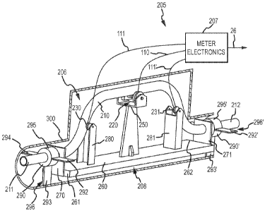
FIG. 2 shows a partial cross-sectional view of a flow meter 205 according to
an
embodiment of the invention. The vibrating flow meter 205 shown is in the form
of a
Coriolis flow meter, comprising a sensor assembly 206, and a balance structure
208.
The one or more meter electronics 207 are connected to sensor assembly 206 via
leads
110, 111, 111' to measure a characteristic of a flowing substance, such as,
for example,
density, mass flow rate, volume flow rate, totalized mass flow, temperature,
and other
information. The meter electronics 207 can transmit the information to a user
or other
processor via lead 26.
The sensor assembly 206 includes a conduit 210 that defines a flow path for
receiving a flowing substance. The conduit 210 may be bent, as shown, or may
be
provided with any other shape, such as a straight configuration or an
irregular
configuration. When sensor assembly 206 is inserted into a pipeline system
which
carries the flowing substance, the substance enters sensor assembly 206
through an inlet
flange (not shown), then it flows through the conduit 210, where a
characteristic of the
9
CA 02764031 2011-11-30
WO 2010/144083 PCT/US2009/046852
flowing substance is measured. Following this, the flowing substance exits the
conduit
210 and passes through an outlet flange (not shown). Those of ordinary skill
in the art
appreciate that the conduit 210 can be connected to the flanges, such as
flanges 106,
shown in FIG. 1, via a variety of suitable means. In the present embodiment,
the
conduit 210 is provided with end portions 211, 212 that extend generally from
connectors 270, 271 and connect to the flanges at their outer extremities.
The sensor assembly 206 of the present example includes at least one driver
220.
The driver 220 includes a first portion connected to a driven member 250 of
the balance
structure 208 and a second portion connected to the conduit 210. The first and
second
portions may correspond to a drive coil and a drive magnet, for example. In
the present
embodiment, the driver 220 preferably drives the driven member 250 and conduit
210 in
phase opposition. As shown in FIG. 3, the driven member 250 and conduit 210
are
preferably driven about bending axis X, which is defined in part by the
connectors 270,
271. According to an embodiment of the invention, the bending axis X
corresponds to
the inlet-outlet conduit axis. The driven member 250 bends from the base 260
and thus,
does not have a stationary bending axis. The driver 220 may comprise one of
many well
known arrangements, including for example, and not limitation piezoelectric
elements
or an electromagnetic coil/magnet arrangement.
As shown in FIG. 2, the sensor assembly 206 includes at least one pick-off and
in
the present embodiment is shown provided with a pair of pick-offs 230, 231.
According
to one aspect of the present embodiment, the pick-offs 230, 231 measure the
motion of
the conduit 210. In the present embodiment, the pick-offs 230, 231 include a
first
portion located on respective pick-off arms 280, 281 and a second portion
located on the
conduit 210. The pick-off(s) may comprise one of many well known arrangements,
including for example, and not limitation piezoelectric elements, capacitance
elements,
or an electromagnetic coil/magnet arrangement. Therefore, like the driver 220,
the first
portion of the pick-off may comprise a pick-off coil while the second portion
of the
pick-off may comprise a pick-off magnet. Those of ordinary skill in the art
will
appreciate that the motion of the conduit 210 is related to certain
characteristics of the
flowing substance, for example, the mass flow rate or density of the flowing
substance
through the conduit 210.
CA 02764031 2011-11-30
WO 2010/144083 PCT/US2009/046852
Those of ordinary skill in the art will appreciate that the one or more meter
electronics 207 receive the pick-off signals from the pick-offs 230, 231 and
provide a
drive signal to the driver 220. The one or more electronics 207 can measure a
characteristic of a flowing substance, such as, for example, density, mass
flow rate,
volume flow rate, totalized mass flow, temperature, and other information. The
one or
more electronics 207 may also receive one or more other signals from, for
example, one
or more temperature sensors (not shown), and one or more pressure sensors (not
shown),
and use this information to measure a characteristic of a flowing substance.
Those of
ordinary skill in the art will appreciate that the number and type of sensors
will depend
on the particular measured characteristic.
As shown in FIG, 2, the sensor assembly 206 may also include a case 300. The
case 300 can be provided to surround and protect at least a portion of the
flow conduit
210. The sensor assembly 206 may also include case connects 290, 290', which
can be
provided to couple the case 300 to the flow conduit 205. The case connects
290, 290'
shown include a first portion 295, 295' coupled to the conduit 210 and a
second portion
296, 296' coupled to the case 300. As shown, the case connects 290, 290' are
preferably the only structures supporting the conduit 210 located between the
flanges
and the connectors 270, 271. It should be appreciated that while the case
connects 290,
290' are shown in conjunction with the flow meter 205, the case connects 290,
290' may
be implemented in prior art flow meters that lack the balancing structure 208
shown in
FIG. 2. For example, the case connects 290, 290' could be implemented in the
prior art
flow meter 100 shown in FIG. 1.
According to one aspect of the present embodiment, the case connects 290, 290'
are preferably configured to provide support for the vibrating system that is
rigid in
axial and transverse movement yet soft in torsional movement. As a result,
according to
an embodiment of the invention, the case connects 290, 290' can substantially
retain the
active flow conduit length. This may be accomplished by providing the case
connects
290, 290' with deformable members 292, 292' 293, 293' 294, 294' for example,
which
extend radially with respect to the axis of the end portions 211, 212 of the
conduit 210.
Although three deformable members 292, 292' 293, 293', 294, 294' are provided
in the
embodiment shown, it should be appreciated that any number of deformable
members
may be utilized and the particular number of deformable members should not
limit the
11
CA 02764031 2011-11-30
WO 2010/144083 PCT/US2009/046852
scope of the present invention. The deformable members 292, 292' 293, 293',
294, 294'
may be coupled to the conduit 210 in any manner, including, for example the
first
portion 295, 295' which may comprise a central hub 295, 295' coupled to the
conduit
210 as in the embodiment shown. According to an embodiment of the invention,
the
central hub 295, 295' may be adapted to receive at least a portion of the flow
conduit
210. More specifically, the central hub 295, 295' may be adapted to receive
the end
portions 211, 212 of the flow conduit 210.
The rigid translational and soft torsional coupling of the case connects 290,
290'
provide at least two functions. First, by limiting the end portions 211, 212
to torsional
movement, the case connects 290, 290' constrain the nodes to the end portion
axes.
While the nodes may relocate on the end portion axes, the movement of the tube
end
portions is constrained by the case connects to rotation about their axes. The
case
connects thus limit measurement errors associated with node relocations.
Secondly, by
allowing the end portions 211, 212 freedom to rotate, the vibrating structure
is supported
torsionally in a very soft manner. The soft torsional mount enables the
amplitude ratio
of the conduit 210 and balance structure 208 to change with fluid density and
enables
the self-balancing feature of the present invention. The combination of these
two
features operates to retain the active flow conduit length despite variations
in fluid
density. The operation of the case connects 290, 290' is explained in more
detail below.
FIG. 3 shows an enlarged view of the case connect 290 coupled to the flow tube
210 and the case 300 according to an embodiment of the invention. Although the
discussion below is limited to the case connect 290, it should be appreciated
that the
case connect 290' operates according to the same principals and therefore a
separate
discussion of the operation of the case connect 290' is omitted. Some of the
components of the flow meter 205 have been removed from FIG. 3 to simplify the
figure. For example, the connector 270 and balance structure 208 are not shown
in FIG.
3. It should be appreciated that in operation, the end portion 211 of the
conduit 210 may
extend out from the case 300 and case connect 290 further than illustrated.
Although
the figure is simplified, it should be appreciated that in operation, the
components
shown in FIG. 2, but not shown in FIGS. 3 & 4 will typically be included.
Furthermore,
FIGS. 3 & 4 only show the portion of the conduit 210 and case 300 coupled to
the case
connect 290. It should be appreciated that the case 300 in operation may
substantially
12
CA 02764031 2011-11-30
WO 2010/144083 PCT/US2009/046852
surround the entire vibrating flow tube 210 as shown in FIG. 2. As can be
seen, the case
connect 290 couples the flow tube 210, and more particularly, the end portion
211 of the
flow tube 210 to the case 300. Advantageously, the case connect 290 retains
the flow
tube 210 in the desired position with respect to the case 300 using the one or
more
deformable members 292, 293, 294.
According to an embodiment of the invention, the first portion 295 of the case
connect 290 is adapted to receive at least a portion of the flow conduit 210.
More
particularly, the first portion 295 is adapted to receive at least a portion
of the end
portion 211 of the flow conduit 210. The first portion 295 may be coupled to
the end
portion 211 in a variety of ways including, but not limited to, brazing,
bonding, welding,
adhesives, mechanical fasteners, etc. In the embodiment shown, the first
portion 295
comprises a central hub 295; however, it should be appreciated that other
configurations
are contemplated. For example, in other embodiments, the deformable members
292,
293, 294 can be coupled directly to the end portion 211 with the end of the
deformable
members 292, 293, 294 comprising the first portion 295. In embodiments where
the
first portion 295 comprises a central hub 295, the central hub 295 can include
an
opening 341 adapted to receive at least a portion of the end portion 211.
In the embodiment shown in FIG. 3, each deformable member 292, 293, 294 is
separated from the next deformable member 292, 293, 294 by an angle a. It
should be
appreciated that the angle a may comprise approximately 90 as shown in FIG.
2, or
may comprise some angle other than 90 as in FIGS. 3 & 4. The particular angle
a
chosen may also depend on the number of deformable members provided in the
particular case connect 290. Therefore, it should be appreciated that the
particular angle
a separating the deformable members 292, 293, 294 should not limit the scope
of the
present invention. However, it should also be appreciated that if the angle a
is
approximately 180 and the case connect 290 only comprises one or two
deformable
members, the ability of the deformable members to limit translational movement
may be
substantially reduced. This is because with only two opposing deformable
members,
rotation would not be the only type of movement that would be perpendicular to
the
plane of both deformable members. Rather, the flow conduit 210 could move a
substantial amount, which could disadvantageously allow the end portions to
bend and
impair the accuracy of the flow meter. The orientation of the deformable
members is
13
CA 02764031 2011-11-30
WO 2010/144083 PCT/US2009/046852
important in determining whether the translational movement will affect the
measurements. For example, in the embodiment shown in FIG. 2, if the
deformable
member 293 were removed, the end portion 211 would be free to move in a
vertical
direction because the planes of the deformable members 292, 294 are
substantially
parallel. Therefore, the tube ends 211, 212 could bend in the vertical plane
and apply
additional Coriolis forces to the fluid. However, this vertical movement may
not affect
the meter's measurements because the pick-off sensors 230, 231 do not measure
movement in this direction. In contrast, if the case connect 290 shown in FIG.
2 were
rotated by approximately 90 and the deformable member 293 were removed, then
the
parallel deformable members 292, 294 could allow the tube ends 211, 212 to
bend in the
horizontal plane. Because the pick-off sensors 230, 231 do measure movement in
this
direction, horizontal translation of the tube ends 211, 212 could affect the
meter
accuracy by generating additional Coriolis forces. However, with the third
deformable
member 293 provided, this horizontal movement can be substantially eliminated.
In
contrast, with the configuration shown in FIGS. 3 & 4 where the deformable
members
292, 294 are separated by an angle less than 180 , the third deformable member
293
could be removed and the case connect 290 could retain its functionality.
According to an embodiment of the invention, with the central hub 295 coupled
to the flow conduit 210 and the deformable members 292, 293, 294 extending
from the
central hub 295 and coupled to the case 300, the flow conduit 210 can be held
securely
in place with respect to the case 300. This is because a single deformable
member can
substantially prevent the end portion 211 of the conduit 210 from moving
parallel to the
plane of the deformable member. This is because such motion would require the
deformable member to stretch or compress. Take for example, the deformable
member
293 that is substantially vertical in FIG. 3 with a plane 340 that is shown
extending to
the end portion 211 for illustrative purposes. The deformable member 293 can
substantially prevent the end portion 211 from moving in a vertical direction
as shown
in FIG. 3 because downward movement would require the deformable member 293 to
compress and upward movement would require the deformable member 293 to
stretch.
Typically, the forces applied to the end portions 211, 212 of the flow conduit
210 are
not great enough to overcome the strength of the deformable members to stretch
or
compress the deformable members. It should be appreciated that the particular
14
CA 02764031 2011-11-30
WO 2010/144083 PCT/US2009/046852
directions described above correspond to the directions shown in FIG. 3 and
therefore,
the applicability of the orientations of "up" and "down" will depend upon the
particular
orientation of the flow meter once installed.
In addition, the deformable members 292, 292' 293, 293', 294, 294' can
substantially prevent the end portions 211, 212 from moving in the axial
direction of the
end portions 211, 212. Movement in this direction would need to overcome the
coupling force between the deformable members 292, 292' 293, 293', 294, 294'
and the
case 300 or between the conduit 210 and the central hub 295, 295' or between
the
central hub 295, 295' and the deformable members 292, 292' 293, 293', 294,
294'. In
some embodiments, the deformable members 292, 292' 293, 293', 294, 294' are
held by
friction; however, in other embodiments, the case connects 290, 290' may be
coupled
using additional methods such as brazing, bonding, welding, adhesives,
mechanical
connectors, etc. Therefore, in these embodiments, in order for the conduit 210
to move
in the axial direction of the end portions 211, 212, i.e., parallel to the
axis X and also
parallel to the plane of the deformable members 292, 292' 293, 293', 294,
294', a force
would be required that could overcome the force coupling the case connects
290, 290' to
the end portions 211, 212 and the case 300. Often, the vibrational forces
experienced by
the flow meter 205 are not great enough to overcome these coupling forces.
With more than one deformable member provided at an angle from the first
deformable member, the additional deformable members can likewise
substantially
prevent the conduit 210 from moving parallel to the plane of the additional
deformable
members. Therefore, the conduit 210 is substantially prevented from moving
parallel to
the plane of the deformable member 292, 292' 293, 293', 294, 294'.
Furthermore, the
deformable members 292, 292' 293, 293', 294, 294' can substantially prevent
the
conduit 210 from moving in the axial direction of the conduit 210. However,
the
conduit 210 is left free to move perpendicular to the deformable member, i.e.,
rotate
about the conduit axis X. This is possible due to the resiliency of the
deformable
members 292, 292' 293, 293', 294, 294'. This is shown further in FIG. 4.
FIG. 4 shows an enlarged view of the case connect 290 according to an
embodiment of the invention. In the embodiment shown, the end portion 211 of
the
flow conduit 210 has rotated in the counter-clockwise direction. For clarity
the rotation
amount has been greatly exaggerated. Because the central hub is coupled to the
end
CA 02764031 2011-11-30
WO 2010/144083 PCT/US2009/046852
portion 211, the central hub has also rotated. This rotation may be due to a
change in
fluid density, for example. Because the deformable members 292, 293, 294 are
coupled
to both the central hub 295 and the case 300, the deformable members 292, 293,
294
have partially deformed due to the rotation of the central hub 295. According
to an
embodiment of the invention, the deformable members 292, 293, 294 may be
formed
from a thin metal sheet, for example. This may provide sufficient strength
along the
plane of the deformable member yet sufficient flexibility to allow the end
portion 211 of
the flow conduit 210 to rotate. It should be appreciated that the deformable
members
292, 293, 294 could be formed from other materials, such as certain polymers.
Those
skilled in the art will readily recognize other suitable materials and
therefore, the
particular examples provided should in no way limit the scope of the present
invention.
It should be appreciated that the deformable members 292, 292' 293, 293', 294,
294'
can be formed such that they are resilient so as to return to their original
shape upon the
end portions 211, 212 and the first portion central hub 295, 295' returning to
their
original position. This elastic deformation allows the deformable members 292,
292'
293, 293', 294, 294' to permit rotation of the central hub 295, 295' and
therefore, the
flow conduit 210 in either direction.
The deformation of the deformable members 292, 293, 294 provides a number of
advantages. One advantage is that the end portion 211 of the flow conduit 210
may
rotate due to a change in fluid density, for example. According to an
embodiment of the
invention, the flow meter 205 may be configured such that the node is located
at the
junction of the flow conduit 210 and the balance structure 208 with a fluid
density of
approximately 1 g/cm3. If a more dense fluid flows through the flow conduit
210 than
originally balanced for, the conduit vibration amplitude will decrease while
the balance
structure 208 vibration amplitude will increase. These changes in vibration
amplitude
allow the flow meter 205 to remain balanced despite a change in fluid density.
In this
situation, the end portions 211, 212 will rotate with the balance structure
208 and the
nodes will move out along the axis of the end portions 211, 212. In prior art
flow
meters, this node relocation caused measurement errors because the end
portions were
allowed to bend. However, in the present invention, the node relocation does
not create
measurement errors, because the movement in the end portions 211, 212 is
limited to
purely rotational movement. According to an embodiment of the invention, this
node
16
CA 02764031 2011-11-30
WO 2010/144083 PCT/US2009/046852
motion will not impact the active flow conduit length because the pure
rotation of the
conduit 210 about its axis does not generate Coriolis forces. Conversely, if
the fluid
density drops, the flow conduit vibration amplitude will increase and the
balance
structure vibration amplitude will decrease to once again restore the meter
balance. In
this situation, the end portions 211, 212 will instead rotate with the flow
conduit 210
rather than the balance structure 208.
Therefore, it can be appreciated that the case connects 290, 290' can limit
the
motion of the end portions 211, 212 of the flow conduit 210 to rotation about
the axis X.
This limitation of movement is provided by the soft rotational mounting
conditions
provided by the case connects 290, 290'. In order for the flow conduit 210 and
the
balance structure 208 to adjust their amplitude ratio by self-balancing, they
should be
suspended in a very soft mount. Prior art soft mounts did not limit the
movement to
rotational movement as in the present invention. Therefore, the node
relocation could
affect meter performance. According to the present invention, the active
portion of the
flow conduit 210 and the balance structure 208 are designed so that the
vibrating
structure is balanced in substantially all translational directions with a
fluid density of
approximately 1 g/cm3. When the fluid density changes, translation forces are
small,
and the motions are easily suppressed by the mass of the case 300 via the
deformable
members 292, 292' 293, 293', 294, 294'. The other significant motion created
by
varying densities is rotation of the end portions 211, 212. The end portions
211, 212 are
also coupled to the flanges (not shown). Thus, the end portions 211, 212
comprise a
long torsion spring extending from the active portion of the flow conduit 210
to the
flange face. The length of this spring allows for a sufficiently soft mounting
structure
for the vibrating structure to be essentially self-balancing. Its length also
allows
relatively little torque to be transmitted to the flanges from the vibrating
conduit 210.
The detailed descriptions of the above embodiments are not exhaustive
descriptions of all embodiments contemplated by the inventors to be within the
scope of
the invention. Indeed, persons skilled in the art will recognize that certain
elements of
the above-described embodiments may variously be combined or eliminated to
create
further embodiments, and such further embodiments fall within the scope and
teachings
of the invention. It will also be apparent to those of ordinary skill in the
art that the
17
CA 02764031 2011-11-30
WO 2010/144083 PCT/US2009/046852
above-described embodiments may be combined in whole or in part to create
additional
embodiments within the scope and teachings of the invention.
Thus, although specific embodiments of, and examples for, the invention are
described
herein for illustrative purposes, various equivalent modifications are
possible within the
scope of the invention, as those skilled in the relevant art will recognize.
The teachings
provided herein can be applied to other vibrating flow meters, and not just to
the
embodiments described above and shown in the accompanying figures.
Accordingly,
the scope of the invention should be determined from the following claims.
18