Note: Descriptions are shown in the official language in which they were submitted.
CA 02764269 2011-12-01
WO 2011/018892 PCT/JP2010/005008
Description
Title of Invention: COMMUNICATION SYSTEM, COMMU-
NICATION APPARATUS, COMMUNICATION METHOD AND
COMPUTER PROGRAM PRODUCT
Technical Field
[0001] The present invention relates to a communication system, a
communication
apparatus, a communication method and a computer program product in which a
base
station communications with a mobile station within a cell through the
mediation of a
relay station. In particular, the present invention relates to a communication
system, a
communication apparatus, a communication method and a computer program product
which employ a relay mode that applies intercell interference coordination.
Background Art
[0002] Communication services become increasingly diverse with widespread use
of in-
formation processing and information communication technology and in
particular, de-
velopment of mobile communication such as mobile phone is remarkable.
Currently,
3GPP (Third Generation Partnership Project) is working on standardization of
the
world standard "IMT (International Mobile Telecommunications) - 2000" of a
third-
generation (3G) mobile communication system drafted by ITU (International
Telecom-
munication Union). "LTE (Long Tenn Evolution)", which is one of data commu-
nication specifications drafted by 3GPP, is a long-term advanced system aimed
at
fourth-generation (4G) IMT-Advanced and is also called "3.9G (super 3G)".
[0003] LTE is a communication mode based on an OFDM (Orthogonal Frequency
Division
Multiplexing) modulation method and adopts OFDMA (OFDM access) as the radio
access method of a downlink. (Down-bound radio access from a base station (BS)
toward a mobile station (MS) is called herein as a "downlink" and up-bound
radio
access from the MS to the BS as an "uplink").
[0004] OFDM is a multi-carrier method by which a plurality of pieces of data
is assigned to
frequency sub-carriers that are "orthogonal", that is, do not interfere with
each other
and can convert each sub-carrier on a frequency axis into a signal on a time
axis for
transmission by performing inverse FFT (Fast Fourier Transform) for each sub-
carrier.
Transmission data is transmitted by being distributed to a plurality of
carriers whose
frequencies are orthogonal and thus, OFDM is characterized in that the band of
each
carrier becomes a narrow band, the efficiency of frequency utilization is very
high, and
delay distortion (frequency selective fading disturbance) is resisted thanks
to multi
paths.
[0005] OFDMA (Orthogonal Frequency Division Multiple Access) is a multiple
access
2
WO 2011/018892 PCT/JP2010/005008
scheme in which, instead of all sub-carriers of an OFDM signal being occupied
by one
communicating station, a set of sub-carriers in the frequency axis is assigned
to a
plurality of communicating stations so that sub-carriers are shared by the
plurality of
communicating stations.
[0006] 3GPP supports a bandwidth close to 100 MHz in a standard specification
"LTE-
Advanced", which is a further development of LTE for a fourth-generation
mobile
communication system, and aims for realization of the peak speed of 1 Gbps at
the
maximum. A space division multiple access scheme in which radio resources on
spatial axes are shared by a plurality of users like, for example, multi-user
MIMO
(MU-MIMO) or SDMA (Space Division Multiple Access) is regarded as very likely.
[0007] Moreover, relay technology is examined for LTE-Advanced to improve
throughput
at cell edges. The relay technology here is a mechanism by which a relay
station (RS)
is installed in an area of a base station connected to a core network to allow
hopping
communication between the base station and the relay station. If the
communication
speed is 1-2 Mbps or so, the modulation method such as BPSK (Binary Phase
Shift
Keying) and QPSK (Quadrature PSK) can be applied and a necessary SNR
(Signal-to-Noise Ratio) is permitted even if the SNR is low. In contrast, to
obtain the
communication speed of 100 Mbps or more, it is necessary to maintain a high
SNR
throughout the cell. Moreover, a higher operating frequency increases
transmission
losses and is sensitive to fading so that a coverage area of a base station
deteriorates.
Performance of a single base station falls at cell edges and a relay station
compensates
therefore.
[0008] In a downlink, the relay station first amplifies a received signal from
a base station
and then transmits the received signal to a mobile station. With a received
signal being
relayed by a relay station, the SNR can be increased when compared with a case
when
a signal is directly transmitted from the base station to the mobile station.
In an uplink,
on the other hand, the relay station can maintain the SNR high by receiving a
signal
from the mobile station and transmitting the signal to the base station.
[0009] For example, a cellular system in which the base station assigns
resources to
terminals, transmits a downlink signal in the current time slot, and receives
an uplink
signal from terminals via a relay station in the next time slot, the relay
station receives
a downlink signal from the base station and an uplink signal from terminals in
the
current time slot and transmits the received downlink signal to the terminals
and the
received uplink signal to the base station in the next time slot, and the
terminal
transmits an uplink signal in the current time slot and receives a downlink
signal via
the relay station in the next time slot (see, for example, Japanese Patent
Application
Laid-Open No. 2008-22558).
[0010] The mode in which a relay station relays a signal between a base
station and a mobile
CA 02764269 2011-12-01
3
WO 2011/018892 PCT/JP2010/005008
station can be classified into the following two types based on how a received
signal is
transmitted.
[0011] The first type is a mode called "Amplify-and-Forward (AF)" in which a
relay station
retransmits a received signal from a base station after amplifying the signal
unchanged
as an analog signal. In the AF mode, it is difficult for the mobile station to
improve the
SNR (Signal-to-Noise Ratio) and thus, it is necessary for the relay station to
relay by
using a region in which signal strength is sufficiently large. Moreover, there
is a
feedback path between a transmitting antenna and a receiving antenna so that
con-
sideration must be given to prevention of oscillation. An advantage of the AF
mode is
that there is no need at all to improve the communication protocol.
[0012] The second type is a mode called "Decode-and-Forward (DF)" in which the
relay
station performs digital processing on a received signal from the base station
and then
amplifies and transmits the received signal. That is, the relay station
converts the
received signal from the base station into a digital signal by the AD
conversion,
performs decode processing such as an error correction on the signal, encodes
the
signal again, and converts the signal into an analog signal by the DA
conversion before
amplifying and transmitting the signal. According to the DF mode, the SNR can
be
improved by a coding gain. Further, an issue of a signal turnaround into
between the
transmitting antenna and the receiving antenna can be avoided by a signal
converted
into a digital signal being stored in a memory and the signal being
transmitted in the
next time slot by the relay station. Oscillation can also be suppressed by
changing the
frequency, instead of the time slot being changed for transmission and
reception.
[0013] In LTE-Advanced, which is a future network of 3GPP, the DF mode capable
of
improving the SNR rather than the AF mode is more likely to be used.
[0014] In LTE and LTE-Advanced, a reduction in communication delay is demanded
and
more specifically, reducing the delay between users to 50 millisecond or less
is
demanded. Thus, when relay technology is introduced, an issue of delay caused
by the
mediation of a relay station needs to be sufficiently considered.
[0015] While the DF-type relay mode improves the SNR by a coding gain, a delay
caused
by decoding and recoding is significant. Thus, a method by which the AF type
that
causes less delay is used for channels in which a delay demand is severe and
the DF
type is applied to channels in which a delay demand is not severe is proposed.
[0016] If relayed in the DF type relay mode by changing the time slot by time
division to
avoid interference, the delay increases in time slot. The delay when a relay
station
recodes and transmits a received signal is frequently aligned with a delay of
one
subframe or time slot. This is because if a relay station should be introduced
while
maintaining downward compatibility of LTE, such delimitation is easier to
maintain
compatibility. One subframe is a delimiter of an uplink and a downlink of TDD
(Time
CA 02764269 2011-12-01
4
WO 2011/018892 PCT/JP2010/005008
Division Duplex) and thus is easier to adopt as the unit of delay of a relay
station.
[0017] In LTE, intercell interference coordination (ICIC) is proposed to
reduce an influence
of interference between adjacent cells of the same channel.
[0018] The ICIC can be realized by, for example, a fractional frequency
repetition
combining a one-cell frequency repetition and a multi-cell frequency
repetition.
[0019] Each cell is divided into a center region inside the cell close to a
base station and a
boundary region at cell ends apart from the base station. While a "central
frequency"
assigned to communication between the base station and the mobile station in
the
center region competes with that of adjacent cells (that is, a one-cell
frequency
repetition), interference between cells is avoided by controlling transmission
power
small enough so that a signal reaches only within the center region. On the
other hand,
it is necessary to transmit a signal large enough so that the signal reaches
the boundary
region and interference between cells is avoided by mutually different
"boundary fre-
quencies" being used by boundary regions of adjacent cells (that is, a multi-
cell
frequency repetition). Moreover, instead of all sub-carriers of an OFDM signal
being
occupied by one mobile station, sub-carriers of the central frequency are
assigned to
mobile stations near the base station and those of boundary frequencies to
mobile
stations apart from the base station so that sub-carriers are shared by a
plurality of
mobile stations to implement multiple access (OFDMA).
[0020] If relay technology is introduced into a cellular system, each link is
to be demul-
tiplexed in terms of the time and frequency to prevent a reception from the
base station
(a relay link) and a retransmission to the mobile station (an access link) of
the relay
station from interfering with each other or to prevent an uplink and a
downlink from
interfering with each other. When intercell interference coordination
(fractional
frequency repetition) is performed, the frequency is different depending on
the position
even in the same cell (using either the central frequency or the boundary
frequency)
and it is necessary to take this point into consideration to avoid
interference between
links.
[0021] If relay technology is introduced, intercell interference coordination
is also necessary
to be taken into consideration.
Citation List
Patent Literature
[0022] PTL 1: Japanese Patent Application Laid-Open No. 2008-22558
Summary of Invention
Technical Problem
[0023] Thus, it is desirable to provide a communication system, a
communication apparatus,
a communication method and a computer program product which are superior, and
in
CA 02764269 2011-12-01
5
WO 2011/018892 PCT/JP2010/005008
which a base station can suitably communicate with a mobile station in a cell
through
the mediation of a relay station.
[0024] It is also desirable to provide a communication system, a communication
apparatus, a
communication method and a computer program product which employ a superior
relay mode capable of suitably performing intercell interference coordination.
[0025] It is also desirable to provide a communication system, a communication
apparatus, a
communication method and a computer program product which are capable of
suitably
relaying between the base station and a mobile station so as to avoid
interference in the
relay station between the relay link and the access link, or the uplink and
the downlink,
using intercell interference coordination.
Solution to Problem
[0026] The present invention addresses the above-identified and other
limitations of con-
ventional systems, methods and computer program product, as will be discussed
in
detail herein.
One such system is a mobile communication system that includes a base station
and a
relay node. The base station includes a transmitter that provides wireless
coverage in a
cell, the cell being divided into a center region and a boundary region, the
center
region being surrounded by the boundary region, an outer edge of the boundary
region
defining an outer edge of the cell, the transmitter transmits using first
wireless
resources allocated to the center region and second wireless resources
allocated to the
boundary region. The relay node is configured to relay signals between said
base
station and said mobile station, and includes a controller that operates the
relay node in
one of a plurality of relay modes that are distinguished based on position
information
of the mobile station and position information of the relay node, respective
of the
plurality of relay modes having predetermined wireless resource assignments
for com-
munications between the base station and relay node, and between the relay
node and
mobile station.
[0027] In this system, a plurality of relay modes respectively define wireless
resources and
times to be used when providing an access link from the mobile station to the
relay
node, and a relay link from the relay node to the base station.
[0028] Likewise, the controller may set the relay mode to be one of a first
relay mode when
the relay node is in the center region and the mobile station is in the
boundary region, a
second relay mode when both the relay node and the mobile station are in the
boundary
region, or a third relay mode when both the relay node and the mobile station
are in the
center region, wherein the transmitter when using the first wireless resources
to cover
the center region transmits at a lower power than when using second wireless
resources
to cover the boundary region.
CA 02764269 2011-12-01
6
WO 2011/018892 PCT/JP2010/005008
[0029] The second relay mode and third relay mode may use mutually exclusive
frequency
bands, and the first relay mode uses combined time division and frequency
division
multiple access, wherein each of an uplink and a downlink employ mutually
exclusive
frequency bands.
[0030] The first relay mode employs at least one of a set of frequency and
time com-
binations. The combinations may include:
employing one of the mutually exclusive frequency bands for the uplink during
a
first time segment, and another of the mutually exclusive frequency bands for
the
downlink during a second time segment, the first time segment not overlapping
the
second time segment;
employing the one of the mutually exclusive frequency bands for the uplink
during
the first time segment, and another of the mutually exclusive frequency bands
for the
downlink during the second time segment, the first time segment not
overlapping the
second time segment; and
employing a first sub-band of the one of the mutually exclusive frequency
bands for
a relay link portion of the uplink and employing a first sub-band of the
another of the
mutually exclusive frequency bands for an access link portion of the uplink,
and
employing a second sub-band of the one of the mutually exclusive frequency
bands for
a relay link portion of the downlink and employing a second sub-band of the
another of
the mutually exclusive frequency bands for an access link portion of the
downlink.
[0031] The mobile communication system may optionally include a position
determination
mechanism configured to determine the position information of the relay node,
the
position determination mechanism being included in one of the relay node and
the base
station.
[0032] The inventive system may also be embodied as a relay node in a mobile
commu-
nication system that provides wireless coverage in a cell of a base station,
the cell
being divided into a center region and a boundary region, the center region
being
surrounded by the boundary region. The relay node includes a transceiver
configured
to relay signals between the base station and the mobile station. The relay
node also
includes a controller that operates the relay node in one of a plurality of
relay modes,
the plurality of relay modes being distinguishable based on position
information of the
mobile station and position information of the relay node, respective of the
plurality of
relay modes having predetermined wireless resource assignments for
communications
between the base station and relay node, and between the relay node and mobile
station.
[0033] With regard to the relay node, the plurality of relay modes
respectively define
wireless resources and times to be used when providing an access link from the
mobile
station to the relay node, and a relay link from the relay node to the base
station.
CA 02764269 2011-12-01
7
WO 2011/018892 PCT/JP2010/005008
[0034] A second relay mode and a third relay mode use mutually exclusive
frequency bands,
and a first relay mode uses combined time division and frequency division
multiple
access, wherein each of an uplink and a downlink employ mutually exclusive
frequency bands.
[0035] The first relay mode employs at least one of a set of frequency and
time com-
binations, the combinations including:
employing one of the mutually exclusive frequency bands for the uplink during
a
first time segment, and another of the mutually exclusive frequency bands for
the
downlink during a second time segment, the first time segment not overlapping
the
second time segment;
employing the one of the mutually exclusive frequency bands for the uplink
during
the first time segment, and another of the mutually exclusive frequency bands
for the
downlink during the second time segment, the first time segment not
overlapping the
second time segment; and
employing a first sub-band of the one of the mutually exclusive frequency
bands for
a relay link portion of the uplink and employing a first sub-band of the
another of the
mutually exclusive frequency bands for an access link portion of the uplink,
and
employing a second sub-band of the one of the mutually exclusive frequency
bands for
a relay link portion of the downlink and employing a second sub-band of the
another of
the mutually exclusive frequency bands for an access link portion of the
downlink.
[0036] An innovative method according to the present invention relays wireless
signals in a
cell, the cell being divided into a center region and a boundary region, the
center
region being surrounded by the boundary region, an outer edge of the boundary
region
defining an outer edge of the cell, the method including:
transmitting signals from a base station using wireless resources allocated to
the
center region and transmitting signals using wireless resources allocated to
the
boundary region, and
relaying signals with a relay node between the base station and the mobile
station,
the relaying step including selecting with a controller a relay mode from a
plurality of
relay modes based on position information of the mobile station and position
in-
formation of the relay node, respective of the plurality of relay modes having
prede-
termined wireless resource assignments for communications between the base
station
and relay node, and between the relay node and mobile station.
[0037] The plurality of relay modes respectively define wireless resources and
times to be
used when providing an access link from the mobile station to the relay node,
and a
relay link from the relay node to the base station.
The plurality of relay modes include a first relay mode when the relay node is
in the
center region and the mobile station is in the boundary region, a second relay
mode
CA 02764269 2011-12-01
8
WO 2011/018892 PCT/JP2010/005008
when both the relay node and the mobile station are in the boundary region,
and a third
relay mode when both the relay node and the mobile station are in the center
region,
wherein the transmitter when using the first wireless resources to cover the
center
region transmits at a lower power than when using second wireless resources to
cover
the boundary region.
[0038] The second relay mode and a third relay mode use mutually exclusive
frequency
bands; and a first relay mode uses combined time division and frequency
division
multiple access, wherein each of an uplink and a downlink employ mutually
exclusive
frequency bands.The first relay mode employs at least one of a set frequency
and time
combinations, the combinations including:
employing one of the mutually exclusive frequency bands for the uplink during
a
first time segment, and another of the mutually exclusive frequency bands for
the
downlink during a second time segment, the first time segment not overlapping
the
second time segment;
employing the one of the mutually exclusive frequency bands for the uplink
during
the first time segment, and another of the mutually exclusive frequency bands
for the
downlink during the second time segment, the first time segment not
overlapping the
second time segment; and
employing a first sub-band of the one of the mutually exclusive frequency
bands for
a relay link portion of the uplink and employing a first sub-band of the
another of the
mutually exclusive frequency bands for an access link portion of the uplink,
and
employing a second sub-band of the one of the mutually exclusive frequency
bands for
a relay link portion of the downlink and employing a second sub-band of the
another of
the mutually exclusive frequency bands for an access link portion of the
downlink.
[0039] The method may also include determining the position information of the
relay node,
the position determination mechanism being included in one of the relay node
and the
base station.
[0040] The innovation may also be implemented in a mobile terminal for use in
a mobile
communication system that provides wireless coverage in a cell from a base
station,
the cell being divided into a center region and a boundary region, the center
region
being surrounded by the boundary region, the mobile terminal including:
a transceiver configured to exchange wireless signals with a base station via
a relay
node;
a non-transitory computer readable medium that holds scheduling information
corre-
sponding to a selected relay mode for the relay node; and
a controller configured to change which wireless resources are used in commu-
nications with the relay node based on the selected relay mode, the relay mode
selected
based on position information of the mobile station and position information
of the
CA 02764269 2011-12-01
9
WO 2011/018892 PCT/JP2010/005008
relay node, respective of the plurality of relay modes having predetermined
wireless
resource assignments for communications between the base station and relay
node, and
between the relay node and mobile station.
[0041] The controller may be configured to selectably operate in a first relay
mode, second
relay mode or third relay mode,
the first relay mode being selected when the relay node is in the center
region and the
mobile station is in the boundary region,
the second relay mode being selected when both the relay node and the mobile
station are in the boundary region, and
the third relay mode being when both the relay node and the mobile station are
in the
center region.
The innovation may also be implemented in a base station in a mobile commu-
nication system that provides wireless coverage in a cell, the cell being
divided into a
center region and a boundary region, the center region being surrounded by the
boundary region, the base station includes a transceiver and controller. The
transceiver
is configured to exchange signals with a mobile station via a relay node. The
controller
selects a relay mode from a plurality of relay modes, the plurality of relay
modes being
distinguishable based on position information of the mobile station and
position in-
formation of the relay node, respective of the plurality of relay modes having
prede-
termined wireless resource assignments for communications between the base
station
and relay node, and between the relay node and mobile station.
[0042] The plurality of relay modes respectively define wireless resources and
times to be
used when providing an access link from the mobile station to the relay node,
and a
relay link from the relay node to the base station.
Advantageous Effects of Invention
[0043] According to the embodiments of the present invention described above,
it is
possible to provide a communication system, a communication apparatus, a commu-
nication method, and a computer program product which employ a superior relay
mode
capable of suitably performing intercell interference coordination.
[0044] Further, according to the embodiments of the present invention
described above, it is
possible to provide a communication system, a communication apparatus, a commu-
nication method, and a computer program product which are superior, and which
are
capable of suitably relaying by a relay mode corresponding to a position where
a relay
station is located in a cell while applying a fractional frequency repetition
as intercell
interference coordination.
[0045] Interference in the relay station between an uplink and a downlink as
well as between
a relay link and an access link can be avoided by deciding a suitable relay
mode in the
CA 02764269 2011-12-01
10
WO 2011/018892 PCT/JP2010/005008
relay station in accordance with each piece of information on position for the
relay
station and the mobile station.
[0046] Interference in the relay station between an uplink and downlink as
well as between a
relay link and an access link can be avoided by deciding the more suitable
relay mode
in the relay station considering communication capabilities of the relay
station in
addition to each piece of information on position of the relay station and the
mobile
station.
[0047] It is possible to offer a relay between the base station and the mobile
station by a
suitable relay mode by which a relay link and an access link do not interfere
with each
other in the relay station in accordance with each piece of information on
position of
the relay station and the mobile station.
[0048] When the relay station and the mobile station are both in the boundary
region, it is
possible to avoid interference in the relay station by adapting the relay mode
that uses
a boundary frequency avoiding interference with adjacent cells for both an
uplink and
a downlink and demultiplexes a relay link and an access link in a time
direction for
each of the uplink and the downlink.
[0049] When the relay station and the mobile station are both in the center
region, it is
possible to avoid interference in the relay station by adapting the relay mode
that uses
a predetermined central frequency and transmission power that does not reach
adjacent
cells for both an uplink and a downlink and demultiplexes a relay link and an
access
link in a time direction for each of the uplink and the downlink.
[0050] When the relay station is in the center region, but the mobile station
is in the
boundary region, it is possible to avoid interference in the relay station by
the relay
mode that uses a predetermined central frequency and transmission power that
does not
reach adjacent cells for a relay link and a boundary frequency avoiding
interference
with the adjacent cells for an access link and demultiplexes the relay link
and the
access link in a time direction for each of an uplink and a downlink
multiplexed in the
time direction.
[0051] When the relay station is in the center region, but the mobile station
is in the
boundary region and the relay station can perform a transmission/reception
operation
simultaneously by multiplexing in a frequency direction, it is possible to
avoid in-
terference in the relay station by the relay mode that uses a predetermined
central
frequency and transmission power that does not reach adjacent cells for a
relay link
and a boundary frequency avoiding interference with the adjacent cells for an
access
link and multiplexes the relay link and the access link in a time direction
for each of an
uplink and a downlink demultiplexed in the time direction.
[0052] When the relay station is in the center region, but the mobile station
is in the
boundary region, the relay station can perform a transmission/reception
operation si-
CA 02764269 2011-12-01
11
WO 2011/018892 PCT/JP2010/005008
multaneously by multiplexing in a frequency direction, and a system frequency
can be
divided into frequencies for a downlink and an uplink, it is possible to avoid
in-
terference in the relay station by the relay mode that uses a predetermined
central
frequency and transmission power that does not reach adjacent cells for a
relay link
and a boundary frequency avoiding interference with the adjacent cells for an
access
link and multiplexes the relay link and the access link in a time direction
for each of an
uplink and a downlink multiplexed in the time direction.
[0053] It is possible to adaptively correspond to the movement of the mobile
station by
selecting the relay mode in the relay station for each predetermined radio
frame.
[0054] Other purposes, features, and advantages of the present invention will
become
evident by a detailed description based on embodiments of the present
invention
described below or appended drawings.
Brief Description of Drawings
[0055] [fig.l]Fig. 1 is a diagram showing a radio frame configuration of a
downlink of LTE.
[0056] [fig.2]Fig. 2 is a diagram showing a basic communication operation
inside a cell
including cases when a relay station mediates and does not mediate.
[0057] [fig.3A]Fig. 3A is a diagram showing a cellular system realizing
intercell interference
coordination by a fractional frequency repetition.
[0058] [fig.3B]Fig. 3B is a diagram illustrating a frequency assignment inside
the cell in
which the fractional frequency repetition is performed.
[0059] [fig.3C]Fig. 3C is a diagram illustrating the frequency assignment
inside the cell in
which the fractional frequency repetition is performed.
[0060] [fig.3D]Fig. 3D is a diagram illustrating the frequency assignment
inside the cell in
which the fractional frequency repetition is performed.
[0061] [fig.4]Fig. 4 is a diagram showing a communication example between a
base station
and mobile stations via relay stations inside the cell in which the intercell
interference
coordination is applied.
[0062] [fig.5]Fig. 5 is a diagram showing how a time slot is demultiplexed in
terms of a time
and a frequency to prevent a relay link and an access link of the relay
station from in-
terfering with each other or to prevent an uplink and a downlink from
interfering with
each other.
[0063] [fig.6]Fig. 6 is a diagram illustrating a relay mode in accordance with
a position where
the relay station is located inside the cell.
[0064] [fig.7]Fig. 7 is a diagram illustrating the relay mode in accordance
with the position
where the relay station is located inside the cell.
[0065] [fig.8]Fig. 8 is a diagram illustrating the relay mode in accordance
with the position
where the relay station is located inside the cell.
CA 02764269 2011-12-01
12
WO 2011/018892 PCT/JP2010/005008
[0066] [fig.9]Fig. 9 is a diagram illustrating the relay mode in accordance
with the position
where the relay station is located inside the cell.
[0067] [fig.10]Fig. 10 is a diagram illustrating the relay mode in accordance
with the position
where the relay station is located inside the cell.
[0068] [fig.1l]Fig. 11 is a diagram illustrating the relay mode in accordance
with the position
where the relay station is located inside the cell.
[0069] [fig.12]Fig. 12 is a diagram illustrating the relay mode in accordance
with the position
where the relay station is located inside the cell.
[0070] [fig.13]Fig. 13 is a flow chart showing a processing procedure for the
base station to
decide the relay mode inside the cell.
[0071] [fig. 14] Fig. 14 is a diagram schematically showing a functional
configuration of the
base station operating in a cellular system according to an embodiment of the
present
invention.
[0072] [fig.15]Fig. 15 is a diagram schematically showing the functional
configuration of the
relay station operating in the cellular system according to an embodiment of
the
present invention.
[0073] [fig.16]Fig. 16 is a diagram schematically showing the functional
configuration of the
mobile station operating in the cellular system according to an embodiment of
the
present invention.
[0074] [fig.17]Fig. 17 is a diagram showing a relationship between a receiving
signal strength
and a communication range from the base station (positions of a relay station
and a
mobile station in a cell).
Description of Embodiments
[0075] An embodiment in which the present invention is applied to a mobile
communication
system such as LTE will be described in detail with reference to drawings.
[0076] Fig. 1 shows a radio frame configuration of a downlink of LTE. As
illustrated in Fig.
1, a radio frame is composed of three hierarchical layers of a time slot
(Slot), a
subframe (Subframe), and a radio frame (Radio Frame) in descending order of
time
unit.
[0077] A time slot of 0.5 millisecond is constituted by seven OFDM symbols
(for normal
unicast transmission) and becomes the unit of decode processing when received
by a
user (mobile station). A subframe of 1 millisecond is constituted by two
consecutive
time slots and becomes the unit of transmission time of a correction-coded
data packet.
A radio frame of 10 millisecond is constituted by 10 subframes (that is, 20
time slots)
and becomes the basic unit for multiplexing of all physical channels.
[0078] Each user can perform communication without mutual interference by
using different
subcarriers or different time slots. In LTE, the minimum unit of radio
resource as-
CA 02764269 2011-12-01
13
WO 2011/018892 PCT/JP2010/005008
signment called a "resource block (RB)" is defined by dividing continuous
subcarriers
into blocks. One resource block has a width of 12 sub carriers in the
frequency axis
direction and a length of 0.5 millisecond (seven OFDM symbols) in the time
axis
direction. A scheduler mounted on a base station assigns radio resources to
each user
in resource blocks. This assignment is specified in a control channel called
"L1/L2
control signaling". Each user recognizes resource blocks assigned to the user
by
viewing the control channel. The resource blocks are assigned for each
subframe, that
is, at intervals of 1 millisecond.
[0079] The time slot of 0.5 millisecond length is the minimum unit of
assignment available
to each user. The scheduler mounted on a base station assigns time slots that
may be
used in units of time slots to each user. In LTE, two duplex systems, FDD
(Frequency
Division Duplex) and TDD (Time Division Duplex), can be selected. In the case
of
TDD, which of an uplink and a downlink to use can be selected for each
subframe.
[0080] In a communication system according to the present embodiment, relay
technology is
introduced for the purpose of improving throughput at cell edges.
[0081] Basic communication operations within a cell including cases when a
relay station
mediates and does not mediate will be described with reference to Fig. 2. A
link
between a base station (BS) and a relay station (RS) is called a "relay link
(RelayLink)" and a link between the relay station and a mobile station (MS) is
called
an "access link (AccessLink)". A direct link between the base station and the
mobile
station without using the relay station is called a "direct link
(DirectLink)". In Fig. 2, a
downlink is denoted as a solid line arrow and an uplink as a broken line
arrow.
[0082] In LTE, radio resources are assigned in resource blocks and specified
by a control
channel called the L1/L2 signaling (mentioned above). A relay station judges
whether
there is any resource block addressed to the relay station by viewing
assignment in-
formation of resource blocks in the control channel, that is, scheduling
information
every 1 millisecond.
[0083] In a downlink, the relay station first amplifies a received signal from
a base station
by, for example, the DF mode (mentioned above) and then transmits the received
signal to a mobile station. With a received signal being relayed by a relay
station, the
Signal-to-Noise Ratio can be increased when compared with a case when a signal
is
directly transmitted from a base station to a mobile station. In an uplink, on
the other
hand, the relay station can maintain the Signal-to-Noise Ratio high by
receiving a
signal from the mobile station and transmitting the signal to the base station
after am-
plifying the received signal.
[0084] Further, in a communication system according to the present embodiment,
the
intercell interference coordination (mentioned above) is applied to reduce an
influence
of interference between adjacent cells of the same channel.
CA 02764269 2011-12-01
14
WO 2011/018892 PCT/JP2010/005008
[0085] The intercell interference coordination will be described again here
with reference to
Figs. 3A to 3D. In the illustrated example, the intercell interference
coordination is
realized by a fractional frequency repetition combining a one-cell frequency
repetition
and a multi-cell frequency repetition (3-cell frequency repetition in Figs. 3A-
3D).
[0086] In Fig. 3A, a hexagon represents one cell range. Each cell is divided
into a white
center region inside the cell and a shaded boundary region at cell ends. The
central
frequency assigned to the center region competes with that of adjacent cells
(that is, the
frequency repetition is 1), but interference between cells is avoided by
controlling
transmission power small enough so that a signal reaches only within a center
region.
On the other hand, different frequencies are assigned to boundary regions of
adjacent
cells (that is, the 3-cell frequency repetition is performed). In Fig. 3A, a
difference in
frequency band is represented by shading types (positive slopes, negative
slopes, and
grid-like slashes). By switching allocation of frequency assignment between
adjacent
cells as illustrated in Figs. 3B-3D, efficient frequency assignment can be
operated.
[0087] Figs. 3B to 3D show frequency assignment inside a cell and transmission
power. In
each cell, the system frequency band is divided into three blocks and a
subcarrier block
used for frequency repetition between cells is assigned to the boundary
frequency and
a subcarrier block for 1-cell frequency repetition to the central frequency.
[0088] In a cell having a boundary region with negative slopes in Fig. 3A, for
example, a
subcarrier block #1 is assigned to the boundary frequency and subcarrier
blocks #2 and
#3 to the central frequency (see Fig. 3B). In a cell having a grid-like shaded
boundary
region in Fig. 3A, the subcarrier block #2 is assigned to the boundary
frequency and
the subcarrier blocks #1 and #3 to the central frequency (see Fig. 3C). In a
cell having
a boundary region with positive slopes in Fig. 3A, the subcarrier block #3 is
assigned
to the boundary frequency and the subcarrier blocks #1 and #2 to the central
frequency
(see Fig. 3D). Multiple access (OFDMA) is realized by, instead of all
subcarriers of an
OFDM signal being occupied by one communicating station, assigning subcarriers
of
the central frequency to a mobile station or relay station in the center
region and sub-
carriers of the boundary frequency to a mobile station or relay station in the
boundary
region to share subcarriers by a plurality of communicating stations.
[0089] In any cell in Fig. 3A, inter-cell interference does not occur even if
the 1-cell
frequency is repeated since transmission power of the central frequency is
controlled to
a transmission power that is small enough so that a signal reaches only within
a center
region of the cell. While transmission power of the boundary frequency is
large enough
so that a radio wave reaches a cell end from the base station in the cell
center, in-
terference between adjacent cells does not occur because a frequency
repetition of a
plurality of cells (three cells in the illustrated example) is used.
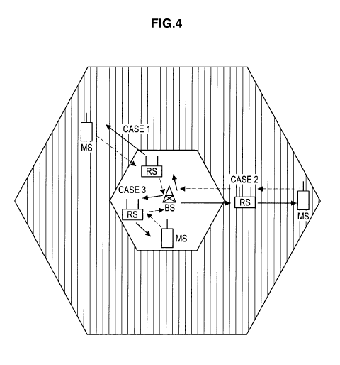
[0090] Fig. 4 shows a communication example between a base station and mobile
stations
CA 02764269 2011-12-01
15
WO 2011/018892 PCT/JP2010/005008
via relay stations inside the cell in which the intercell interference
coordination is
applied. In Fig. 4, a downlink is denoted as a solid line arrow and an uplink
as a broken
line arrow.
[0091] As illustrated in Fig. 4, for each of the relay station and the mobile
station, both cases
of being located in the center region and the boundary region can be
considered. In
Case 1 in Fig. 4, a relay station in the center region relays to a mobile
station in the
boundary region. In Case 2, a relay station and a mobile station belonging
thereto are
both located in the boundary region. In Case 3, a relay station and a mobile
station
belonging thereto are both located in the center region.
[0092] The relay mode will be considered with reference to Fig. 4.
Demultiplexing in terms
of the frequency can easily be considered to prevent an uplink and a downlink
from in-
terfering with each other in a relay station. Further, demultiplexing in terms
of the time
slot can easily be considered to prevent a relay link and an access link from
interfering
with each other in the relay station.
[0093] Fig. 5 shows how a time slot is demultiplexed in terms of the time and
frequency to
prevent a relay link and an access link from interfering with each other or to
prevent an
uplink and a downlink from interfering with each other in the relay station.
In Fig. 5, a
solid line arrow denotes a downlink and a broken line arrow an uplink. Each
time a
relay station is passed through, the time slot is demultiplexed. This is
depicted by the
smaller arrows in Figure 5. For a direct link, the time slot can be used
continuously,
which is depicted as longer arrows in Figure 5.
[0094] The horizontal axis in Fig. 5 is a time axis and the vertical axis is a
frequency axis.
Each of four squares corresponds to what is called "resource blocks" in LTE
and a
scheduler mounted in a base station assigns resource blocks. Each resource
block can
multiplex each channel in the time direction and frequency direction.
[0095] During a downlink, a base station transmits a signal by using a
resource block of the
time slot of time Ti and of a frequency F2 (a relay link of the downlink). A
relay
station receives the signal in the relay link of the downlink and after
storing the signal
in a buffer, transmits the signal by using a resource block of the time slot
of time T2
and of a frequency F2 (an access link of the downlink). Then, a mobile station
receives
the signal in the access link of the downlink using the time slot of time T2
and of the
frequency F2. Note that the direct link of the downlink is a link to
communicate
directly from the base station to the mobile station, not through the relay
station, but in
Fig. 5, it uses the resource block of the frequency F2 successively over the
time slots of
time Ti and time T2.
[0096] During an uplink, on the other hand, a mobile station transmits a
signal by using a
resource block of the time slot of time Ti and of the frequency F1 (an access
link of
the uplink) and a relay station receives the signal. Then, the relay station
receives the
CA 02764269 2011-12-01
16
WO 2011/018892 PCT/JP2010/005008
signal in the access link of the uplink and after buffering the signal,
transmits the signal
by using a resource block of the time slot of time T2 and of the frequency F 1
(a relay
link of the uplink) and a base station receives the signal. Note that the
direct link of the
uplink is a link to communicate directly from the mobile station to the base
station not
through the relay station, but it uses the resource block of the frequency F1
suc-
cessively over the time slots of time Ti and time T2.
[0097] Note that it is described above that each of the four squares in Fig. 5
corresponds re-
spectively to what is called resource blocks in LTE. The size of the time
direction of
the square may be a time slot separated by a resource blocks, or may be a sub
frame
that is a time slot of two resource blocks. For a preferable embodiment, the
latter may
be easier to be operated.
[0098] Further, if a standard frequency bandwidth for transmitting/receiving
in a cell is
20MHz, a resource block includes 12 sub-carriers with intervals of 15kHz,
therefore,
the size of the frequency direction of the square in Fig. 5 is 180kHz in
width. The
frequency assignment of the central frequency and the boundary frequency in
the
intercell interference coordination has been illustrated in Fig. 3B, Fig. 3C,
Fig. 3D.
This is used by dividing the resource block at 180 kHz increments into
approximately
three regions over a system bandwidth of 20 MHz. On the other hand, a method
to bind
a plurality of frequency bands to communicate may be considered. For example,
in
case of using carrier aggregation that communicates in a bandwidth of binding
five
bandwidths of 20 MHz (100 MHz in total), three frequency bands (see Figures 3B-
3D)
of the intercell interference coordination could be separated by 20 MHz guard
bands
(60 MHz used for signaling and 40 MHz used for separation). Therefore, the
size of
the square in Fig. 5 in the frequency direction may be a bandwidth of 20MHz.
[0099] Incidentally, when intercell interference coordination (fractional
frequency
repetition) is performed, the frequency used for communication is different
depending
on the position of the mobile station even in the same cell and it is
necessary to
consider that a mobile station in the center region uses the central frequency
and a
mobile station in the boundary region uses the boundary frequency (mentioned
above).
[0100] It is natural to think that a mobile station that needs a relay station
is located in the
boundary region. In such a case, it is reasonable to use the boundary
frequency for
communication between the relay station and the mobile station, that is, for
an access
link. On the other hand, two cases of the relay station can be considered:
being in the
center region and the boundary region. In other words, both cases of the use
of the
central frequency and the boundary frequency can be considered for a relay
link. In
Fig. 4, three use cases of Cases 1 to 3 are shown as communication examples
between
a base station and a mobile station via a relay station in a cell. If a
central frequency F1
is used in the center region and a boundary frequency F2 in the boundary
region, fre-
CA 02764269 2011-12-01
17
WO 2011/018892 PCT/JP2010/005008
quencies used by a relay link and an access link in each case can be
summarized as the
table shown below:
[0101] [Table 1]
Relay link frequency Access link frequency
Case 1 F1 F2
Case 2 F2 F2
Case 3 FI Fl
[0102] Referring to Fig. 5 again, the same frequency is used for a relay link
and an access
link for each of an uplink and a downlink so that the relay link and access
link, and the
uplink and downlink of the relay station should not interfere with each other.
In Table
1, in contrast, Case 1 (relay node in central region and MS in boundary
region) uses the
central frequency for a relay link and the boundary frequency for an access
link. In
other words, the relay link and the access link use different frequencies so
that Fig. 5
shows an inappropriate relay mode.
[0103] From the viewpoint of using the boundary frequency for both a relay
link and an
access link in Case 2 (both relay node and MS are in boundary region), on the
other
hand, Fig. 5 may show an appropriate relay mode. Though Case 3 (both relay
node and
MS are in the central region) in which a mobile station in the center region
is relayed
by a relay station is rare, Fig. 5 may also show an appropriate relay mode
from the
viewpoint of using the central frequency for both a relay link and an access
link.
However, in the example shown in Fig. 4, Case 2 is Case 2 for both an uplink
and a
downlink and similarly Case 3 is Case 3 for both an uplink and a downlink.
That is, the
same frequency is used for both an uplink and a downlink. In contrast, the
relay mode
shown in Fig. 5 is configured to have demultiplexed frequencies for an uplink
and a
downlink (the boundary frequency F2 is used for a downlink and the central
frequency
F1 for an uplink) and is not desirable, since it would either give rise to
inefficient use
of shared wireless resources (e.g., frequencies used in multiple cells) or
intercell in-
terference.
[0104] As identified by the present inventor, the relay mode shown in Fig. 5
is not desirable
in any of Cases 1 to 3 in Fig. 4.
[0105] From the above description, a relation between intercell interference
coordination
(fractional frequency repetition) and a relay station will be summarized.
While a
mobile station that needs a relay by a relay station is normally located in
the boundary
region, both cases of being located in the center region and the boundary
region can be
CA 02764269 2011-12-01
18
WO 2011/018892 PCT/JP2010/005008
considered for a relay station. Thus, it is necessary to provide a relay mode
corre-
sponding to the position where a relay station is located in a cell (that is,
which of the
center region and the boundary region the relay station is located).
[0106] Figs. 6 to 10 exemplify relay modes that can be applied to one of Cases
1 to 3 shown
in Fig. 4 in accordance with the position where a relay station is located in
a cell. In all
relay modes, a scheduler mounted on a base station assigns time slots by demul-
tiplexing a time slot in terms of the time and frequency in such a way that a
relay link
and an access link of a relay station do not interfere with each other and
also an uplink
and a downlink do not interfere with each other.
[0107] The relay mode shown in Fig. 6 is applicable for Case 3 and uses a
predetermined
central frequency F1 and the transmission power that is not enough to reach
adjacent
cells for both an uplink and a downlink, demultiplexes the uplink and downlink
in the
time direction, and demultiplexes a relay link and an access link for each of
the uplink
and downlink. This relay mode is suitable for a case when both a mobile
station and a
relay station are located in the center region corresponding to, for example,
Case 3 in
Fig. 4. The possibility that a relay station mediates for communication with a
base
station in which a mobile station is located in the center region is low.
Nevertheless, it
is possible, such as when a mobile station is deep inside a building or
tunnel, it is
desirable to relay by a relay station near a window of the building or near an
entrance
of the tunnel.
[0108] During a downlink, a base station transmits a signal in the time slot
of time Ti by
using resource blocks of the central frequency F1 (a relay link of the
downlink). A
relay station receives the signal in the relay link of the downlink and after
storing the
signal in a buffer, transmits the signal in the time slot of time T2 by using
resource
blocks of the central frequency F1 (an access link of the downlink). Then, a
mobile
station receives the signal in the access link of the downlink in the time
slot of time T2
using resource blocks of the central frequency Fl.
[0109] During an uplink, on the other hand, a mobile station transmits a
signal in the time
slot of time T3 by using resource blocks of the central frequency F1 (an
access link of
the uplink) and a relay station receives the signal. Then, the relay station
receives the
signal in the access link of the uplink and after buffering the signal,
transmits the signal
in the time slot of time T4 by using resource blocks of the central frequency
F1 (a relay
link of the uplink) and a base station receives the signal.
[0110] In the example shown in Fig. 6, the resource blocks are not
demultiplexed in the
frequency direction, but an uplink and a downlink are demultiplexed in the
time
direction. In contrast, as a modification is shown in Fig. 11, which is
applicable for
Case 3, the central frequency F1 may be divided into two frequencies F1-1 and
F1-2 to
multiplex the downlink and the uplink in the frequency direction, but not
unnecessarily
CA 02764269 2011-12-01
19
WO 2011/018892 PCT/JP2010/005008
use frequencies allocated for the boundary region.
[0111] During a downlink, a base station transmits a signal in the time slot
of time Ti by
using resource blocks of the frequency F1-2 (a relay link of the downlink). A
relay
station receives the signal in the relay link of the downlink and after
storing the signal
in a buffer, transmits the signal in the time slot of time T2 by using
resource blocks of
the frequency F1-2 (an access link of the downlink). Then, a mobile station
receives
the signal in the access link of the downlink in the time slot of time T2
using resource
blocks of the frequency F2.
[0112] During an uplink, on the other hand, a mobile station transmits a
signal by using a
resource block of the time slot of time Ti and of the frequency F1-1 (an
access link of
the uplink) and a relay station receives the signal. Then, the relay station
receives the
signal in the access link of the uplink and after buffering the signal,
transmits the signal
by using a resource block of the time slot of time T2 and of the frequency F1-
1 (a relay
link of the uplink) and a base station receives the signal.
[0113] The relay mode illustrated in Fig. 7 relates to Case 2 and uses the
boundary
frequency F2 that avoids interference with adjacent cells for both an uplink
and a
downlink, demultiplexes the uplink and downlink in the time direction, and
demul-
tiplexes a relay link and an access link in the time direction in each of the
uplink and
downlink. This relay mode is suitable for a case when both a mobile station
and a relay
station are located in the boundary region corresponding to, for example, Case
2 in Fig.
4.
[0114] During a downlink, a base station transmits a signal in the time slot
of time Ti by
using resource blocks of the boundary frequency F2 (a relay link of the
downlink). A
relay station receives the signal in the relay link of the downlink and after
storing the
signal in a buffer, transmits the signal in the time slot of time T2 by using
resource
blocks of the boundary frequency F2 (an access link of the downlink). Then, a
mobile
station receives the signal in the access link of the downlink in the time
slot of time T2
using resource blocks of the boundary frequency F2.
[0115] During an uplink, on the other hand, a mobile station transmits a
signal in the time
slot of time T3 by using resource blocks of the boundary frequency F2 (an
access link
of the uplink) and a relay station receives the signal. Then, the relay
station receives
the signal in the access link of the uplink and after buffering the signal,
transmits the
signal in the time slot of time T4 by using resource blocks of the boundary
frequency
F2 (a relay link of the uplink) and a base station receives the signal.
[0116] In the example shown in Fig. 7, the resource blocks are not
demultiplexed in the
frequency direction, but an uplink and a downlink are demultiplexed in the
time
direction. In contrast, as a modification is shown in Fig. 12, which relates
to Case 2,
the boundary frequency F2 may be divided into two frequencies F2-1 and F2-2 to
CA 02764269 2011-12-01
20
WO 2011/018892 PCT/JP2010/005008
multiplex the downlink and the uplink in the frequency direction.
[0117] During a downlink, a base station transmits a signal in the time slot
of time Ti by
using resource blocks of the frequency F2-2 (a relay link of the downlink). A
relay
station receives the signal in the relay link of the downlink and after
storing the signal
in a buffer, transmits the signal in the time slot of time T2 by using
resource blocks of
the frequency F2-2 (an access link of the downlink). Then, a mobile station
receives
the signal in the access link of the downlink in the time slot of time T2
using resource
blocks of the frequency F2-2.
[0118] During an uplink, on the other hand, a mobile station transmits a
signal by using a
resource block of the time slot of time Ti and of the frequency F2-1 (an
access link of
the uplink) and a relay station receives the signal. Then, the relay station
receives the
signal in the access link of the uplink and after buffering the signal,
transmits the signal
by using a resource block of the time slot of time T2 and of the frequency F2-
1 (a relay
link of the uplink) and a base station receives the signal.
[0119] The relay mode illustrated in Fig. 8 relates to Case 1 and uses a
predetermined
central frequency F1 and transmission power that is not enough to reach
adjacent cells
for a relay link and a boundary frequency F2 that avoids interference with
adjacent
cells for an access link in each of an uplink and a downlink multiplexed in
the time
direction. This relay mode demultiplexes the relay link and the access link in
the
frequency direction and multiplexes the downlink and the uplink in the time
direction
(the relay link and access link are demultiplexed in the frequency direction
and the
time direction in each of the downlink and uplink and also the downlink and
uplink are
multiplexed in the time direction). This relay mode is suitable for a case
when a relay
station located in the central region relays to a mobile station located in
the boundary
region corresponding to, for example, Case 1 in Fig. 4. The relay mode
illustrated
basically uses the central frequency F1 for the relay link and the boundary
frequency
F2 for the access link. The longer arrows represent direct links, and indicate
that the
base station and mobile station change frequencies in time slots of times Ti
and T2.
[0120] During a downlink, a base station transmits a signal in the time slot
of time Ti by
using resource blocks of the central frequency F1 (a relay link of the
downlink). A
relay station receives the signal in the relay link of the downlink and after
storing the
signal in a buffer, transmits the signal in the time slot of time T2 by using
resource
blocks of the boundary frequency F2 (an access link of the downlink). Then, a
mobile
station receives the signal in the access link of the downlink in the time
slot of time T2
using resource blocks of the boundary frequency F2.
[0121] During an uplink, on the other hand, a mobile station transmits a
signal in the time
slot of time Ti by using resource blocks of the boundary frequency F2 (an
access link
of the uplink) and a relay station receives the signal. Then, the relay
station receives
CA 02764269 2011-12-01
21
WO 2011/018892 PCT/JP2010/005008
the signal in the access link of the uplink and after buffering the signal,
transmits the
signal in the time slot of time T2 by using resource blocks of the central
frequency F1
(a relay link of the uplink) and a base station receives the signal.
[0122] The relay mode illustrated in Fig. 9 also relates to Case 1 and
demultiplexes the
uplink and downlink in the time direction and multiplexes the relay link and
the access
link in the frequency direction (the downlink and uplink are demultiplexed in
the time
direction, while the relay link and the access link are multiplexed in the
frequency
direction the time direction). For the downlink, the relay mode uses the
predetermined
central frequency F1 and transmission power that is not enough to reach
adjacent cells
for the relay link, and uses the boundary frequency F2 that avoids
interference with
adjacent cells for the access link as well. On the other hand, for the uplink,
the relay
mode uses the boundary frequency F2 that avoids interference with adjacent
cells for a
relay link, and uses the predetermined central frequency F1 and the
transmission power
that is not enough to reach adjacent cells for the access link The vertical
lines in the
figure depict a linkage between the relay link and access link being for an
uplink or
downlink and show that data from an originating source (e.g., base station) is
then
forwarded (by the relay node) to the destination (e.g., MS). Generally, this
relay mode
is suitable, same as Fig. 8, for a case when a relay station located in the
central region
relays to a mobile station located in the boundary region corresponding to,
for
example, Case 1 in Fig. 4.
[0123] As a downlink, a base station transmits a signal in the time slot of
time Ti by using
resource blocks of the central frequency F1 (a relay link of the downlink).
While
receiving the signal in the relay link of the downlink, a relay station
transmits the
signal in the time slot of the same time Ti by using resource blocks of the
boundary
frequency F2 (an access link of the downlink). Then, a mobile station receives
the
signal in the access link of the downlink in the time slot of time Ti using
resource
blocks of the boundary frequency F2.
[0124] As an uplink, on the other hand, a mobile station transmits a signal in
the time slot of
time T2 by using resource blocks of the boundary frequency F2 (an access link
of the
uplink) and a relay station receives the signal. Then, while receiving the
signal in the
access link of the uplink, the relay station transmits the signal in the time
slot of time
T2 by using resource blocks of the central frequency F1 (a relay link of the
uplink) and
a base station receives the signal.
[0125] The relay mode shown in Fig. 9 is similar to that shown in Fig. 8 in
that the central
frequency F1 is used for a relay link and the boundary frequency F2 for an
access link,
but is different in that the relay link and access link are multiplexed in the
frequency
direction in each of a downlink and an uplink and has an advantage that a
delay
involved in relay is slight. However, the relay station in this case needs a
circuit
CA 02764269 2011-12-01
22
WO 2011/018892 PCT/JP2010/005008
because the relay station performs a transmission/reception operation
multiplexed in
the frequency axis direction (that is, a transmission/reception operation is
performed at
the same time) such as transmitting at the boundary frequency F2
simultaneously while
receiving at the central frequency F I.
[0126] The relay mode illustrated in Fig. 10 also relates to Case 1 and uses a
predetermined
central frequency and transmission power that is not enough to reach adjacent
cells for
a relay link, and uses a boundary frequency that avoids interference with
adjacent cells
for an access link in each of an uplink and a downlink to multiplex the relay
link and
the access link in the frequency direction, while dividing the central
frequency and the
boundary frequency into halves (sub-bands) for the uplink and downlink to
multiplex
both the uplink and downlink in the frequency direction. This relay mode is
suitable,
same as Fig. 8 and 9, for a case when a relay station located in the central
region relays
to a mobile station located in the boundary region corresponding to, for
example, Case
1 in Fig. 4.
[0127] As a downlink, a base station transmits a signal in the time slot of
time Ti by using
resource blocks of the central frequency F1-1 (a relay link of the downlink).
While
receiving the signal in the relay link of the downlink, a relay station
transmits the
signal in the time slot of the same time Ti by using resource blocks of the
boundary
frequency F2-1 (an access link of the downlink). Then, a mobile station
receives the
signal in the access link of the downlink in the time slot of time Ti using
resource
blocks of the boundary frequency F2- 1.
[0128] As an uplink, on the other hand, a mobile station transmits a signal in
the time slot of
time Ti by using resource blocks of the boundary frequency F2-2 (an access
link of the
uplink) and a relay station receives the signal. Then, while receiving the
signal in the
access link of the uplink, the relay station transmits the signal in the time
slot of time
Ti by using resource blocks of the central frequency F1-2 (a relay link of the
uplink)
and a base station receives the signal.
[0129] The relay mode shown in Fig. 10 is similar to that shown in Fig. 8 in
that the central
frequency F1 is used for a relay link and the boundary frequency F2 for an
access link,
but the relay link and access link are multiplexed in the frequency direction
in each of
a downlink and an uplink. The relay station in this case needs a circuit to
perform a
transmission/reception operation at the same time.
[0130] The relay mode shown in Fig. 10 is different from the relay mode shown
in Fig. 9 in
that the central frequency F1 is divided into two frequencies Fl-1 and F1-2,
divides the
boundary frequency F2 into two frequencies F2-1 and F2-2, and further a
downlink
and an uplink are also multiplexed in the time direction, and has an advantage
that a
delay involved in relay is still slighter. Whether the relay mode shown in
Fig. 10 can
be adopted depends also on whether occupation of four frequency bands
(division into
CA 02764269 2011-12-01
23
WO 2011/018892 PCT/JP2010/005008
two of each of the central frequency and the boundary frequency by a relay
station) is
permitted for communication with the relevant mobile station.
[0131] Applicability of each relay mode shown in Figs. 6 to 10 to each of
Cases 1 to 3
shown in Fig. 4 is summarized in the table below.
[0132] [Table 2]
Case Case 1 Case 2 Case 3
Mode
Fig. 6 0
Fig. 7 0
Fig. 8 0
Fig. 9 0
Fig. 10 0
[0133] A base station controls communication operations of a downlink and an
uplink with a
mobile station through a relay by a relay station in a unifying fashion and it
is
necessary for the base station to demultiplex a time slot in terms of the time
and
frequency in such a way that a relay link and an access link of a relay
station do not
interfere with each other and also an uplink and a downlink do not interfere
with each
other. As is evident from Table 2, the relay mode (that is, resource
assignment to a
relay link and an access link in a downlink and an uplink) needs to be decided
in con-
sideration of positions in a cell of the relay station and mobile station.
[0134] Thus, in a cellular system according to the present embodiment, the
base station
designates the relay mode for a relay station in the local cell according to
each item
below:
[0135] (1) Position of a relay station (which of the center region and
boundary region the
relay station is located in)
[0136] (2) Position of a mobile station belonging to the relay station (which
of the center
region and boundary region the mobile station is located in)
[0137] (3) Whether the relay station can perform a transmission/reception
operation simul-
taneously by multiplexing in the frequency direction
[0138] Fig. 13 shows a processing procedure for the base station to decide the
relay mode of
the relay station inside the cell in a flow chart form.
[0139] First, whether different frequencies should be used for a relay link
and an access link,
CA 02764269 2011-12-01
24
WO 2011/018892 PCT/JP2010/005008
that is, whether the central frequency should be used for a relay link and the
boundary
frequency for an access link is checked (step S 1). Step Si corresponds to
judgments of
the above items (1) and (2).
[0140] If different frequencies are used for a relay link and an access link
(Yes in step S 1), a
judgment is made that positions of the relay station and mobile station
correspond to
Case 1 in Fig. 4 (step S2). In this case, communication capabilities, that is,
whether the
relay station can perform a transmission/reception operation simultaneously by
mul-
tiplexing in the frequency direction is further checked listed in the above
item (3) (step
S3).
[0141] If it is difficult for the relay station to perform a
transmission/reception operation si-
multaneously by multiplexing in the frequency direction (No in step S3), the
relay
mode shown in Fig. 8 is set (step S6).
[0142] If a judgment is made that the rely station can perform a
transmission/reception
operation simultaneously by multiplexing in the frequency direction (Yes in
step S3),
subsequently, whether occupation of four frequency bands is permitted for
commu-
nication with the relevant mobile station is checked (step S4).
[0143] If occupation of four frequency bands is permitted for communication
with the
relevant mobile station (Yes in step S4), the relay mode shown in Fig. 10 is
set (step
S6). If occupation of four frequency bands is not permitted for communication
with the
relevant mobile station (No in step S4), the relay mode shown in Fig. 9 is set
(step S7).
[0144] If, on the other hand, a judgment is made that the same frequency is
used for a relay
link and an access link (No in step Si), subsequently, whether the central
frequency is
used for both a relay link and an access link is checked (step S8).
[0145] If the central frequency is used for both a relay link and an access
link (Yes in step
S8), positions of the relay station and mobile station can be judged to
correspond to
Case 3 in Fig. 4 and the relay mode shown in Fig. 6 is set (step S9).
[0146] If the boundary frequency is used for both a relay link and an access
link (No in step
S8), positions of the relay station and mobile station can be judged to
correspond to
Case 2 in Fig. 4 and the relay mode shown in Fig. 7 is set (step S 10).
[0147] Then, the base station signals the relay mode decided according to the
above
processing procedure to the relevant relay station and mobile station.
[0148] The base station may perform the processing procedure shown in Fig. 13,
when
updating an assignment of the radio resources in the local cell. It is
arbitrary how often
the assignment of the radio resource in the local cell is updated. For
example, the base
station may perform the processing procedure shown in Fig. 13 for each radio
frame to
update assignment of radio resources in the local cell. In such a case, the
relay mode
can adaptively be changed for each radio frame in accordance with movement of
the
mobile station.
CA 02764269 2011-12-01
25
WO 2011/018892 PCT/JP2010/005008
[0149] A network operation mode that is static to some extent may be applied,
instead of re-
peatedly updating in radio frame unit. That is, a company may continue to use
the
same relay mode in a cell for a long period of time, about a year, for
example. On the
other hand, a more dynamic allocation can be used based on scheduled events
(e.g.,
monthly) or demand usage (e.g., network usage in an area that has expanded
over time
and now requires intercell coordination to accommodate its mobile
subscribers). In
other words, the subject matter of the present invention includes an operation
mode in
which a company implements more than two relay modes and uses each of them
separately. Further, besides a case where a base station determines a relay
mode based
on information on positions of the relay station and the mobile station, the
base station
may adapt a relay mode set by the company, such as where a system
administrator sets
(programmably or physically) the relay mode to be employed by the base
station. Op-
tionally, the base station or network administrator may send a control signal
to all
network resources indicating the time and parameters of the mode change.
[0150] In step S 1, whether the same frequency is used for a relay link and an
access link (or
whether one of the central frequency and the boundary frequency is used for
each of a
relay link and an access link) can be judged based on which of the center
region and
the boundary region of a cell the target relay station and mobile station are
located in.
Moreover, the base station can determine in which region, either the central
region or
the boundary region, the relay station and the mobile station locate, based on
the com-
munication range with each of the stations.
[0151] Here, the communication range between communicating stations can be
measured
from the receiving signal strength indicator (RSSI). When receiving a radio
signal
from the relay station and the mobile station, the base station may obtain the
receiving
signal strength from each of the stations. Fig. 17 shows a relationship
between the
receiving signal strength and the communication range from the base station
(positions
of the relay station and the mobile station in a cell). As shown, the more
distant the
relay station and the mobile station locate from the base station, the more
the receiving
signal strength weakens. It can be estimated that a position where the
receiving signal
strength is stronger than the predetermined threshold is a central region, a
position
where the receiving signal strength is weaker than the predetermined threshold
is a
boundary region. Further, the base station may determine which to use, either
the
central region or the boundary region, for each of the relay link and the
access link
based on the estimated result of the positions of the relay station and the
mobile
station. The threshold of the strong vs. weak RSSI may be dynamically changed
to ac-
commodate system demands. For example, if the network operator determines that
more resources are being used in the central region than the boundary region
(perhaps
indicating a new cell site) the RSSI strong/weak threshold may be decreased to
allow
CA 02764269 2011-12-01
26
WO 2011/018892 PCT/JP2010/005008
for boundary frequencies to be used more often. On the other hand, more
crowded
areas may make it prudent to increase the RSSI strong/weak threshold to avoid
more
intercell interference. Likewise, the base station can shift its radiated
power levels to
set a different size for a center region to accommodate traffic demands.
[0152] Moreover, as another method how the base station obtains information on
the
position of the relay station and the mobile station, there may be a method to
inform
the base station of information on a position measured by GPS using a channel
of an
uplink while the relay station and/or the mobile station use a GPS (Global
Positioning
System) to determine position. The base station may determine which to use,
either the
central frequency or the boundary frequency, for each of the relay link and
the access
link based on information on the position notified by the relay station and
the mobile
station. This position information may dynamically change based on movement of
the
relay node or the MS, and the base station is kept appraised of the movement
to allow
for shifting of wireless resources.
[0153] Moreover, as yet another method how the base station obtains
information on the
position of the relay station and the mobile station, there may be a method to
utilize an
initialization procedure used when the relay station and the mobile station
access a
network. As one of the initialization procedures to access the network, a
random access
is to be performed. At a time of random access, the base station can obtain
information
on how long a delay of a signal transmitted from the relay station and the
mobile
station is (timing advanced value). Since the delay is large if the
communication range
is long, and the delay is small if the communication range is short, the base
station can
estimate the positions of the relay station and the mobile station based on
the timing
advanced value. Thus, as the estimation result, the base station may determine
which to
use, either the central frequency or the boundary frequency fro each of the
relay link
and the access link. However, the subject matter of the present invention is
not limited
to a specific measurement method.
[0154] As yet a further alternative, the mobile station and relay node may
report to the base
station whether they can receive control signals from other base stations on
boundary
frequencies. If they can, this indicates that the mobile station and/or relay
node are in
the boundary region.
[0155] Fig. 14 schematically shows a functional configuration of the base
station operating
in a cellular system according to the present embodiment. An illustrated base
station
1400 is constituted by an antenna unit 1401, an analog unit 1402 that performs
analog
processing of a transmission/reception signal, an AD/DA processing unit 1403
that
performs digital conversion of an analog reception signal or analog conversion
of a
digital transmission signal, a digital unit 1404 that performs digital
processing of a
transmission/reception signal, and an upper layer protocol processing unit
1405 that
CA 02764269 2011-12-01
27
WO 2011/018892 PCT/JP2010/005008
performs a data transmission request, reception data processing and the like.
[0156] The base station 1400 has, for example, a plurality of antenna elements
as the
antenna unit 1401 and adopts the space division multiple access scheme in
which radio
resources on spatial axes are shared by a plurality of users like multi-user
MU-MIMO
or SDMA to realize high-throughput communication, which is not, however,
directly
related to the gist of the present invention and thus is herein omitted.
[0157] The upper layer protocol processing unit 1405 can also be constituted
as a general
computer system such as a personal computer, which is not, however, directly
related
to the gist of the present invention and thus is herein omitted.
[0158] The digital unit 1404 includes, in addition to a demodulation/decoding
unit 1411 that
performs demodulation and decoding processing of a reception signal and an
encoding/modulation unit 1412 that performs encoding and modulation processing
of a
transmission signal, functional modules such as a mobile station position
holding
memory 1413, a relay station position holding memory 1414, a relay mode
decision
unit 1415, and a scheduling information generation unit 1416 to perform
management
of the radio resource in the local cell, that is, scheduling. The functional
modules 1413
to 1416 can be constituted by dedicated hardware, but can also be realized by
a prede-
termined software program being executed by a processor.
[0159] When positions of a relay station 1500 (described below) in a local
cell and a mobile
station 1600 (described below) belonging to the relay station 1500 are
measured or
estimated based on a digital reception signal on which demodulation and
decoding
processing has been performed by the demodulation/decoding unit 1411, results
thereof are stored in the relay station position holding memory 1414 and the
mobile
station position holding memory 1413 respectively. Communication ranges to the
relay
station 1500 and the mobile station 1600 can be measured based on, for
example, the
receiving signal strength indicator to detect positions thereof based on
results thereof.
When receiving a radio signal from the relay station 1500 and the mobile
station 1600,
the base station 1400 obtains the receiving signal strength from each of
stations, and
determines a frequency to use (as described before). Moreover, information on
position
of the relay station 1500 and the mobile station 1600, which is treated by the
base
station 1400, may be at such a level that to which of the center region and
boundary
region the position information belongs is detected. The receiving signal
strength or
the frequency to use may be stored, in the mobile station position holding
memory
1413 and in a relay station position holding memory 1414, as information on
positions
instead of information on positions as a resultant converted from the
receiving signal
strength.
[0160] The relay mode decision unit 1415 decides the relay mode according to
the
processing procedure shown in Fig. 13 based on the position of the relay
station 1500
CA 02764269 2011-12-01
28
WO 2011/018892 PCT/JP2010/005008
stored in the relay station position holding memory 1414, the position of the
mobile
station 1600 stored in the mobile station position holding memory 1413, and
commu-
nication capabilities (that is, whether a transmission/reception operation can
be
performed simultaneously by multiplexing in the frequency direction) of the
relay
station 1500. For example, a relay mode is adaptively selected from relay
modes
shown in Figs. 6 to 10.
[0161] The scheduling information generation unit 1416 as a scheduler assigns
radio
resources to the relay station 1500 and the mobile station 1600 belonging
thereto
conforming to the relay mode decided by the relay mode decision unit 1415 to
generate
scheduling information in the local cell. The relay station 1500 and the
mobile station
1600 are notified of the scheduling information through a control channel.
[0162] Fig. 15 schematically shows the functional configuration of the relay
station
operating in the cellular system according to the present embodiment. An
illustrated
relay station 1500 is constituted by an antenna unit 1501, an analog unit 1502
that
performs analog processing of a transmission/reception signal, an AD/DA
processing
unit 1503 that performs digital conversion of an analog reception signal or
analog
conversion of a digital transmission signal, and a digital unit 1504 that
performs digital
processing of a transmission/reception signal.
[0163] The relay station 1500 has, for example, a plurality of antenna
elements as the
antenna unit 1501 and may adopt the space division multiple access scheme
(same as
above), but the gist of the present invention is not limited to this.
[0164] The digital unit 1504 is constituted by a transmission/reception
control unit 1515 that
controls operations of transmission/reception units (collectively the
transmitter related
components, receiver related components and controller components being a
transceiver), a scheduling information holding memory 1516 that stores
scheduling in-
formation and a relay mode transmitted from the base station 1400 through the
control
channel, a Relay mode instruction information holding memory 1517, and a CPU
(Central Processing Unit) 1518 that controls operations inside the digital
unit 1504 in a
unifying fashion. The transmission/reception units are constituted by a
synchronization
unit 1511 that acquires synchronization from digital reception signals, a
demodulation/
decoding unit 1512 that performs demodulation and decoding processing of a
reception
signal according to the acquired synchronization, a buffer 1514 that
temporarily holds
transmission data, and an encoding/modulation unit 1513 that performs encoding
and
modulation processing of a transmission signal. The communication capabilities
of the
transmission/reception unit is arbitrary. In other words, it is arbitrary
whether or not a
transmission/reception operation simultaneously by multiplexing in a frequency
direction.
[0165] The transmission/reception control unit 1515 controls reception
processing in a relay
CA 02764269 2011-12-01
29
WO 2011/018892 PCT/JP2010/005008
link and transmission processing in an access link of a downlink and also
reception
processing in an access link and transmission processing in a relay link of an
uplink
using specified resource blocks according to scheduling information stored in
the
scheduling information holding memory 1516 and the relay mode stored in the
Relay
mode instruction information holding memory 1517 .
[0166] The buffer 1514 has data received in a relay link of a downlink and
addressed to a
mobile station 1600 (described later) or data received in an access link of an
uplink and
addressed to the base station 1400 stored temporarily therein and transmits
the data to
the mobile station 1600 as an access link of the downlink or to the base
station 1400 as
a relay link of the uplink. The relay station 1500 temporarily holds a signal
to be
relayed in the buffer 1514 after demodulating and decoding the signal and then
encodes and modulates the signal again for transmission. That is, the DF mode
(mentioned above) is applied.
[0167] Fig. 16 schematically shows the functional configuration for the mobile
station
operating in a cellular system according to the present embodiment. An
illustrated
mobile station 1600 is constituted by an antenna unit 1601, an analog unit
1602 that
performs analog processing of a transmission/reception signal, an AD/DA
processing
unit 1603 that performs digital conversion of an analog reception signal or
analog
conversion of a digital transmission signal, a digital unit 1604 that performs
digital
processing of a transmission/reception signal, and an upper layer protocol
processing
unit 1605 that performs a data transmission request, reception data processing
and the
like.
[0168] The mobile station 1600 has, for example, a plurality of antenna
elements as the
antenna unit 1601 and may adopt the space division multiple access scheme
(same as
above), but the gist of the present invention is not limited to this. The
upper layer
protocol processing unit 1605 can also be constituted as a general computer
system
such as a personal computer (same as above).
[0169] The digital unit 1604 is constituted by a synchronization unit 1611
that acquires syn-
chronization from digital reception signals, a demodulation/decoding unit 1612
that
performs demodulation and decoding processing of a reception signal according
to the
acquired synchronization, an encoding/modulation unit 1613 that performs
encoding
and modulation processing of a transmission signal, a scheduling information
holding
memory 1614 that stores scheduling information transmitted from the base
station
1400 through the control channel, and a CPU 1615 that controls operations
inside the
digital unit 1604 in a unifying fashion.
[0170] The scheduling information holding memory 1614 has resource blocks
assigned to
the local station stored therein as scheduling information. The
synchronization unit
1611 and the demodulation/decoding unit 1612 perform reception processing by
using
CA 02764269 2011-12-01
30
WO 2011/018892 PCT/JP2010/005008
resource blocks assigned for an access link of a downlink. The
encoding/modulation
unit 1613 performs a transmission operation by using resource blocks assigned
for an
access link of an uplink.
[0171] It should be understood that, by arranging the base station 1400, the
relay station
1500, and the mobile station 1600, respectively illustrated in Fig. 14 to 16,
in the cell
of the base station 1400, a cooperative operation of these communication
stations
causes the decision of an appropriate relay mode in the relay station in
accordance with
each piece of position information of the relay station 1500 and the mobile
station
1600, and interference in an uplink and a downlink as well as in a relay link
and an
access link can be avoided in the relay station 1500.
[0172] Note that the processing procedure illustrated in Fig. 13 is to be
executed by the base
station to determine the relay mode of the relay station in the local cell,
and the con-
figuration example of the base station 1400 illustrated in Fig. 14 and the
configuration
example of the relay station illustrated in Fig. 15 are premised on the base
station 1400
determining the relay mode of the relay station 1500 in the local cell. As its
alternative
example, there may be a method that the relay station, instead of the base
station, de-
termines the relay mode. In such an alternative example, the relay station is
to be
informed by the base station of information on positions of the relay station
itself and
the mobile station in the cell of the base station, or information on the
receiving signal
strength from the relay station and the mobile station that is received by the
base
station. Alternatively, the relay mode can be determined if the relay station
collects
such information by itself. Moreover the relay node need not report an actual
position
to the base station, but rather a determination of whether it is located in
the center
region or boundary region. Once again, this determination can be made based on
(1)
GPS, (2) signal strength of frequencies dedicated to the center region, (3)
propagation
delay, and (4) relative transmission strength from adjacent base stations.
[0173] Moreover, the processing to determine the relay mode can be dispersed
on more than
two different devices (for example, a base station and a relay station),
considering dif-
ferences between the access link and the relay link, or differences between
the uplink
and the downlink. For example, there may be a case where the base station
determines
the relay link from the base station to the relay station, but the relay
station determines
which relay mode is adapted for the access link from the relay station to the
mobile
station.
Industrial Applicability
[0174] In the foregoing, the present invention has been described in detail
with reference to
specific embodiments. However, it is self-evident that persons skilled in the
art can
modify or replace such embodiments without deviating from the gist of the
present
CA 02764269 2011-12-01
31
WO 2011/018892 PCT/JP2010/005008
invention.
[0175] Herein, the description has focused on embodiments obtained by applying
the present
invention to a mobile communication system, but the gist of the present
invention is
not limited to this. The present invention can similarly be applied to various
commu-
nication systems including wireless LANs in which a base station and a mobile
station
communicate through the mediation of a relay station.
[0176] In summary, the present invention has been disclosed in the form of
exemplification
and content described herein should not be interpreted restrictively. Claims
should be
considered for judging the gist of the present invention.
Reference Signs List
[0177] 1400 Base station
1401 Antenna unit
1402 Analog unit
1403 AD/DA processing unit
1404 Digital unit
1405 Upper layer protocol processing unit
1411 Demodulation/decoding unit
1412 Encoding/modulation unit
1413 Mobile station position holding memory
1414 Relay station position holding memory
1415 Relay mode decision unit
1416 Scheduling information generation unit
1500 Relay station
1501 Antenna unit
1502 Analog unit
1503 AD/DA processing unit
1504 Digital unit
1511 Synchronization unit
1512 Demodulation/decoding unit
1513 Encoding/modulation unit
1514 Buffer
1515 Transmission/reception control unit
1516 Scheduling information holding memory
1517 Relay mode instruction information holding memory
1518 CPU
1600 Mobile station
1601 Antenna unit
CA 02764269 2011-12-01
32
WO 2011/018892 PCT/JP2010/005008
1602 Analog unit
1603 AD/DA processing unit
1604 Digital unit
1605 Upper layer protocol processing unit
1611 Synchronization unit
1612 Demodulation/decoding unit
1613 Encoding/modulation unit
1614 Scheduling information holding memory
1615 CPU
CA 02764269 2011-12-01