Note: Descriptions are shown in the official language in which they were submitted.
CA 02764342 2012-01-13
SIDE-FED SHIELDED INTERNAL FUEL MANIFOLD INLET TUBE
The present application is a divisional application of CA
2,495,169 filed January 27, 2005.
TECHNICAL FIELD
[0001] The present invention relates to gas turbine
engines, and most particularly to fuel distribution to
combustors of such engines.
BACKGROUND
[0002] In a gas turbine engine, fuel is generally
supplied to a combustor through a plurality of fuel nozzles
in fluid communication with a fuel manifold. The fuel
manifold receives fuel from one or more fuel inlet tubes.
[0003] Known inlet tubes generally have a single channel
or two concentric channels, and the fuel is fed axially in
each channel. The pressure of the axially fed fuel creates a
considerable force along the axial direction of the tube
which acts on the fuel manifold. This force is transferred
to the support structure of the manifold, as well as the
joints between the inlet tubes and the manifold, which can
lead to a premature rupture thereof.
[00041 Since the combustor operates at high temperatures,
engine fuel system components must be adequately protected
against heat damage. Heat shields are often provided on the
inlet tubes for such protection. However, heat shields can
represent a significant weight increase for the fuel system.
[0005) Because of these high temperatures, a fuel leak
could result in a fire. Thus, it is desirable that the fuel
system be leak proof, and include a safe way to dispose of
leaked fuel should a leak occur. A double walled
construction is often used on inlet tubes and other conduits
in order to provide an annular passageway for leaked fuel.
CA 02764342 2012-01-13
Such a construction can also significantly increase the
weight of the fuel system.
[0006] Accordingly, there is a need for a heat shielded
fuel inlet tube that can provide for adequate disposition of
leaked fuel while having a minimal weight.
[0007] There is also a need for a fuel inlet tube that
can reduce the force transmitted along the axial direction
of the tube to the manifold by fuel pressure.
SUMMARY OF INVENTION
[0008] There is accordingly provided, in accordance with
an aspect of the present invention, an inlet tube for
supplying fuel to a fuel manifold in a gas turbine engine,
the fuel manifold lying in a plane substantially
perpendicular to a central axis of the fuel manifold, the
inlet tube comprising: a tube body defining a central axis
extending between an inlet of the tube body and an outlet of
the tube body; at least a first and a second fuel channel
defined through the tube body between said inlet and said
outlet, the first and second fuel channels being located
side by side within the tube body, outlets of the first and
second fuel channels being in fluid communication with the
manifold; and at least a portion of the tube body being
offset from said plane of the fuel manifold.
[0009] There is also provided, in accordance with another
aspect of the present invention, an inlet tube for supplying
fuel to a manifold of a combustor in a gas turbine engine,
the manifold defining a manifold plane, the inlet tube
comprising: a tube body having a first and a second channel
therein providing fluid flow communication between first and
second ends of the tube body, the first and second channels
respectively defining a first and a second channel axis
extending between said first and second ends, at least a
portion of the channel axis defining a tube body plane
distinct from the manifold plane, the first and second
-2-
CA 02764342 2012-01-13
channel axes being offset from one another and extending at
least partially within the tube plane.
[0010] There is also provided, in accordance with another
aspect of the present invention, a fuel manifold assembly
for a combustor in a gas turbine engine, the fuel manifold
assembly comprising: an internal fuel manifold ring having
at least one fuel flow passage, the internal fuel manifold
ring defining a manifold plane substantially perpendicular
to a central manifold axis; the ring having a radially-outer
periphery; and an inlet tube having a tube body defining at
least first and second fuel channels therein extending side
by side between an inlet and an outlet of the tube body, the
outlet being engaged with the internal fuel manifold ring at
the radially-outer periphery and being in fluid flow
communication with said fuel flow passage, at least a
portion of the tube body defining a tube body plane which is
spaced apart from the manifold plane and within which the
first and second fuel channels lie.
[0011] There is also provided, in accordance with another
aspect of the present invention, an inlet tube for supplying
fuel to a manifold of a combustor in a gas turbine engine,
the inlet tube comprising: a tube body having first and
second ends; a first longitudinal channel defined in the
tube body, the first longitudinal channel having an outlet
in fluid communication with the manifold and a side feed
inlet located in an outer surface of the tube body between
the first and second ends, the side feed inlet being
disposed within a first circumferential groove defined in
the outer surface, the first circumferential groove forming
a first circumferential channel when the inlet tube is
received within a mating part of an engine casing; and two
0-rings concentric with each other and disposed about the
tube body at longitudinally spaced apart points thereon, the
two O-rings being disposed on opposite sides of the side
feed inlet of the first longitudinal channel to sealingly
-3-
CA 02764342 2012-01-13
enclose the side feed inlet between the two O-rings when the
tube body is received within said mating part.
[0012] There is also provided, in accordance with another
aspect of the present invention, an inlet tube for supplying
fuel to a manifold of a combustor in a gas turbine engine,
the inlet tube comprising a tube body having means for
providing fluid flow communication between first and second
ends of the tube body, the second end of the tube body being
for engagement with the manifold, and means for sealingly
isolating two side fuel inlets disposed in respective
circumferential groves in the tube body proximate said first
end, said circumferential grooves each forming a separate
enclosed circumferential channel when the inlet tube is
received within a mating part of an engine casing, said two
side fuel inlets being in fluid flow communication with said
means for providing fluid flow communication between the
first and second ends of the tube body, said means for
sealingly isolating the two side fuel inlets being
concentric with each other about the tube body.
[0013] There is further provided, in accordance with
another aspect of the present invention, a fuel manifold
assembly for a combustor in a gas turbine engine, the fuel
manifold assembly comprising: an internal fuel manifold
having at least one fuel flow passage; and an inlet tube
having a tube body extending between a first and a second
end, the first end being engaged with the internal fuel
manifold, first and second fuel channels extending through
the tube body and each having an inlet and an outlet, the
outlets being in fluid flow communication with said fuel
flow passage of said internal fuel manifold, the inlets of
said first and second fuel channels respectively being a
first and a second side fuel inlet located in an outer
surface of the tube body between said first and second ends,
the first and second side fuel inlets being disposed within
respective first and second circumferential grooves defined
in the outer surface; and three O-rings concentric with each
-4-
CA 02764342 2012-01-13
other and disposed about the tube body, the 0-rings being
longitudinally spaced apart to sealingly isolate the first
and second side fuel inlets which are each respectively
located between two of the three 0-rings.
BRIEF DESCRIPTION OF THE DRAWINGS
[0014] Having thus generally described the nature of the
invention, reference will now be made to the accompanying
drawings, showing by way of illustration a preferred
embodiment thereof and in which:
[0015] Fig.l is a side view of a gas turbine engine, in
partial cross-section, exemplary of an embodiment of the
present invention;
[00161 Fig.2 is a side view of a fuel inlet tube equipped
with a heat shield, exemplary of a preferred embodiment of
the present invention;
[0017] Fig.3 is a side view of the fuel inlet tube of
Fig.2 with the heat shield removed;
[0018] Fig.4 is a front view, in cross-section, of the
fuel inlet tube of Fig.2 connected to a fuel manifold; and
[00191 Fig.5 is a side view, in cross-section, of the
fuel inlet tube and fuel manifold of Fig.4.
DESCRIPTION OF THE PREFERRED EMBODIMENTS
[0020] Fig.l illustrates a gas turbine engine 10 of a
type preferably provided for use in subsonic flight,
generally comprising in serial flow communication a fan 12
through which ambient air is propelled, a multistage
compressor 14 for pressurizing the air, a combustor 16 in
which the compressed air is mixed with fuel and ignited for
generating an annular stream of hot combustion gases, and a
turbine section 18 for extracting energy from the combustion
gases.
-5-
CA 02764342 2012-01-13
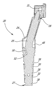
[0021] Referring to Figs.4-5, a fuel inlet tube generally
indicated at 20 has a distal end 26 and a proximal end 27.
The distal end 26 is connected to a fuel manifold 21 which
usually surrounds the combustor 16 and delivers fuel to a
plurality of fuel nozzles located within the combustor. The
inlet tube 20 preferably comprises a primary channel 22 and
a secondary channel 23, both channels being axially defined
in the tube and being located side by side. In the present
text, the terms "axial" and "radial" are defined relative to
the inlet tube 20 and correspond, respectively, to the
directions indicated by arrows A and R in Fig.4. The
channels 22,23 are in fluid communication with the manifold
21. The inlet tube 20 is covered by a heat shield 24 at the
distal end 26, the heat shield 24 being in contact with the
manifold 21 in order to protect the inlet tube 20 against
heat damage. The inlet tube 20 can include a bend 25, which
is defined along an axis perpendicular to a plane including
the axes of both channels 22,23, in order to compensate for
an offset between the fuel manifold and the fuel source
without compromising a fuel flow in the channels 22,23. Such
a bend eliminates the need for a multi-piece assembly and
thus reduces the need for weld or braze during assembly.
[0022] Referring to Figs. 2 to 5, two circumferential
grooves 30,32 are defined in the inlet tube 20 near the
proximal end 27. Into the upper circumferential groove 30 is
defined a first side feed inlet 34 which is in fluid
communication with the secondary channel 23. Similarly, a
second side feed inlet 36 is defined in the lower
circumferential groove 32 and is in fluid communication with
the primary channel 22. When the tube 20 is installed in the
engine casing, a mating part (not shown) will close the
grooves 30,32, thereby forming circumferential channels.
Sealing the two grooves 30,32 are a series of o-rings (not
shown) seated in grooves 38.
[0023] Referring to Figs.4-5, a free space between the
heat shield 24 and the tube 20 defines a chamber 48. The
-6-
CA 02764342 2012-01-13
chamber 48 is adapted to receive fuel which might leak from
the joint between the inlet tube 20 and the manifold 21. A
drain channel 50 is provided in the inlet tube 20 and is in
fluid communication with the chamber 48. The drain channel
50 reaches the outer surface of the inlet tube 20, defining
therein a drain hole 52. The chamber 48, drain channel 50
and drain hole 52 form a drain system effectively directing
leaked fuel along a determined leak path directing the fuel
overboard.
[0024] In operation, fuel is injected in the grooves
30,32 and enters the channels 22,23 through the side feed
inlets 34,36. The side feed inlets 34,36 allow the pressure
of the injected fuel to be generally directed in a radial
direction, thereby reducing the axial force produced by the
fuel pressure. This reduces the axial force acting on the
manifold 21. The fuel then travels through the channels
22,23 and enters the manifold 21 to be delivered to fuel
nozzles.
[0025] If a leak happens at the joint between the inlet
tube 20 and the manifold 21, the leaked fuel is received in
the chamber 48. The leaked fuel is then evacuated overboard
through the drain channel 50 and drain hole 52, where it is
safely disposed of and can be easily noticed. The drain
system therefore provides for ready leak detection without
the need to disassemble the inlet tube 20.
[0026] The inlet tube 20 is preferably manufactured by
turning, then drilling of the channels, and finally bending
of the tube if required.
[0027] The present invention therefore provides for a
reduction of the axial force reacting on the manifold, thus
reducing the wear of the manifold and its supporting means
which increases their useful life. The present invention
also provides for a heat shield that ensures protection from
heat damage as well as fuel leakage control, combining two
functions in one component and thus reducing the weight of
the fuel inlet tube.
-7-
CA 02764342 2012-01-13
[0028] Although a preferred embodiment of the invention
includes both primary and secondary channels 22,23, it is
also contemplated to provide an inlet tube 20 having a
single channel with a side feed inlet, or any other number
of similar channels.
[0029] The embodiments of the invention described above
are intended to be exemplary. Those skilled in the art will
therefore appreciate that the forgoing description is
illustrative only, and that various alternatives and
modifications can be devised without departing from the
spirit of the present invention. Accordingly, the present
is intended to embrace all such alternatives, modifications
and variances which fall within the scope of the appended
claims.
-8-