Note: Descriptions are shown in the official language in which they were submitted.
,
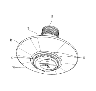
CA 02764467 2016-10-20
CONCEALED SPRINKLER
Technical Field
[00021 The present invention relates generally to fire protection
devices and more
specifically to concealed fire protection sprinklers used preferably, for
example, in concrete
ceiling and/or other residential installations.
Background Art
100031 Concealed-type fire protection sprinklers, which discharge a
fire fighting
fluid such as a water, gas or other chemical agent, can be designed to protect
a variety of
occupancies, both commercial and residential. Generally, the concealed nature
of these
sprinklers obscures the internal components of the sprinkler from view for at
least aesthetic
reasons depending upon the given installation. In addition or in the
alternative, the
concealing structure of the concealed-type sprinkler can protect the internal
components
from either tampering or accidental impact. Regardless of the purpose of the
concealing
structure of the sprinkler, it is critical that the concealing structure not
interfere with the
thermal responsiveness or operation of the sprinkler. This is particularly
true in which the
concealed-type sprinkler must satisfy a response time requirement or standard
in order to be
listed under anyone of the applicable installation/sprinkler standards for a
particular
occupancy such as, for example, protection of a residential occupancy.
- 1 -
CA 02764467 2011-12-02
WO 2010/141948
PCT/US2010/037636
Disclosure of Invention
[0004] The present invention is directed to a concealed-type sprinkler that
includes a
concealing structure that does not interfere with the thermal and operational
components of
the sprinkler. More preferably, the concealing structure facilitates the
thermal responsiveness
of the sprinkler. In addition, the preferred concealed-type sprinkler provides
for a compact
assembly which enhances the ability of the sprinkler to provide an
aesthetically pleasing
installed appearance.
[0005] One preferred embodiment of the sprinkler includes a body having a
proximal portion
defining an opening and a distal portion defining an outlet. The body defines
an internal
passageway having an inlet and an outlet spaced apart along a longitudinal
axis. The distal
portion preferably includes an annular wall having an outer surface and an
inner surface to
further define a chamber distal of the outlet to house an internal component
of the sprinkler.
A cover plate assembly preferably substantially conceals the chamber. The
cover plate
assembly further preferably has a thermally responsive surface exposed to the
chamber to
actuate the sprinkler. The preferred sprinkler preferably includes a spacing
member disposed
between and preferably engaged with the annular wall and the cover plate
assembly. The
spacing member preferably provides means for defining at least one aperture
which provides
communication between the chamber and the environment external to the chamber
or
sprinkler, such that the surface of the cover plate that is exposed to the
chamber is also
exposed to the external environment. In another preferred embodiment of the
sprinkler, an
escutcheon is disposed about the annular wall. The escutcheon includes a
proximal end face
and a distal end face. The escutcheon further preferably tapers in the
proximal to distal
direction toward the axis such that the distal end face of the escutcheon is
located proximally
of the spacing member.
-2-
01737-8053.W000/LEGAL18462740.1
CA 02764467 2011-12-02
WO 2010/141948
PCT/US2010/037636
[0006] The spacing member is preferably formed as a ring member. The preferred
ring
member includes an upper surface and a lower surface, the lower surface having
a plurality of
radially spaced apart posts which define the apertures and engage the cover
plate assembly.
Brief Description of Drawings
[0007] The accompanying drawings, which are incorporated herein and constitute
part of this
specification, illustrate exemplary embodiments of the invention, and
together, with the
general description given above and the detailed description given below,
serve to explain the
features of the invention. It should be understood that the preferred
embodiments are some
examples of the invention as provided by the appended claims.
[0008] FIG. 1 is a first embodiment of a preferred concealed sprinkler
assembly.
[0009] FIG. 2 is a cross-sectional view of the concealed sprinkler assembly of
FIG. 1.
[0010] FIG. 2A is a cross-sectional view of another preferred concealed
sprinkler.
[0011] FIG. 2B is a partial exploded view of the sprinkler of FIG. 1.
[0012] FIG. 2C is partial detailed cross-sectional view of a trigger,
deflector and cover plate
assembly for use in a preferred concealed sprinkler.
[0013] FIG. 2D is an exploded view of a preferred cover plate assembly for use
in the
concealed sprinkler in FIG. 2.
[00141 FIG. 2E is a partial cross-sectional view of the sprinkler assembly of
FIG. 2 in an
actuated position.
[0015] FIG. 2F is a partial cross-sectional view of a trigger, deflector and
cover plate
assembly for use in a preferred concealed sprinkler.
[0016] FIG. 3 is a detailed isometric view of a preferred sprinkler body and
escutcheon
assembly for use in the concealed sprinkler of FIG. 1.
[0017] FIG. 3A is a preferred embodiment of a spacing member as used in the
sprinkler of
FIGS. 2 & 2A.
-3-
01737-8053.W000/LEGAL18462740.1
CA 02764467 2011-12-02
WO 2010/141948
PCT/US2010/037636
[0018] FIG. 3B is preferred embodiment of a lever for use in the sprinkler of
FIG. 1.
[0019] FIGS. 4, 4A, 4B & 4C is preferred deflector for use with the concealed
sprinkler of
FIG. 1.
[0020] FIGS. 5A & 5B is another preferred deflector for use with the concealed
sprinkler of
FIG. 1.
[0021] FIGS. 6A & 6B is another preferred deflector for use with another
preferred
embodiment of concealed sprinkler.
[0022] FIGS. 7A & 7B is a preferred sprinkler body for use in a preferred
sidewall sprinkler.
[0023] FIGS. 8A, 8B & 8C is one embodiment of a deflector for use with the
sidewall
sprinkler body of FIG. 7A.
[0024] FIGS. 9 & 9A is another embodiment of a deflector for use with the
sidewall sprinkler
body of FIG. 7A.
[0025] FIGS. 10 & 10A is another embodiment of a deflector for use with the
sidewall
sprinkler body of FIG. 7A.
[0026] FIG. 11 is another embodiment of a trigger assembly for use in the
sprinkler of FIG.
1.
[0027] FIG. 12 is another embodiment of a trigger assembly for use in the
sprinkler of FIG.
[0028] FIG. 13 is another embodiment of a trigger assembly for use in the
sprinkler of FIG.
1.
Mode(s) For Carrying Out the Invention
[0029] Shown in FIGS. 1 and 2 is an illustrative embodiment of a concealed-
type sprinkler
10, which is preferably configured in accordance with either one of or both
Underwriters
Laboratories, Inc. ("UL") Standard 1626 (2004) or later versions, i.e.,
(2008), entitled
"Residential Sprinklers for Fire Protection Service" and UL Standard 199
(2004) or later
-4-
01737-8053 W000/LEGAL18462740.1
,
CA 02764467 2016-10-20
versions, i.e., (2008), entitled, "Automatic Sprinklers for Fire-Protection
Service." The
concealed-type sprinkler 10 is further preferably configured for use in a
commercial,
institutional, concrete and/or a residential applications as defined by
applicable installation
requirements of anyone of National Fire Protection Association (NFPA)
Standards: NFPA-
13 (2007) or later versions, i.e., (2010) entitled, "Standards for the
Installation of Sprinkler
Systems"; NFPA-13D (2007) or later versions, i.e., (2010) entitled, "Standards
for the
Installation of Sprinkler Systems in One-and Two-Family Dwellings and Mobile
Homes";
and NFPA-13R (2007) or later versions, i.e., (2010) entitled, "Standards for
the Installation
of Sprinkler Systems In Residential Occupancies up to and Including Four
Stories in
Height." The sprinkler 10 can be configured for pendent style mounting with a
pendent
style deflector as shown, for example, in FIG. 1, or alternatively, the
sprinkler 10 can be
configured for sidewall or substantially horizontal mounting with a sidewall
deflector as
shown, for example, in FIGS. 7-10A.
10030] Referring again to FIGS. 1 and 2, the preferred sprinkler 10
generally
includes a sprinkler body 12 that defines an internal chamber for housing
internal sprinkler
components such as, for example, a deflector assembly and an internal trigger
assembly.
The sprinkler 10 further includes a cover plate assembly 16, which at least
partially conceals
the internal components of the sprinkler and preferably doubles as a thermally
rated link
device to define the thermal rating and sensitivity of the sprinkler.
[0031] To ensure the desired thermal responsiveness of the sprinkler, the
sprinkler 10
preferably includes one or more spacing members 17 disposed between the
sprinkler body
12 and the cover plate assembly 16 to define a plurality of openings 19
radially spaced about
the internal chamber of the sprinkler 10 such that both the upper (proximal)
and lower
(distal) surfaces of the link device of the cover plate assembly 16 are
exposed to the external
- 5 -
CA 02764467 2011-12-02
WO 2010/141948
PCT/US2010/037636
environment. Heat from a fire can pass through the openings 19 to flow about
the upper and
lower surfaces of the link device of the cover plate assembly 16 so that the
sprinkler 10 can
respond in a desired manner. Accordingly, the preferred spacing member 17
provides a
means for controlled heat transfer or flow between the external environment
and the
internally concealed surfaces of the trigger device of the cover plate
assembly to ensure that
the sprinkler is sufficiently thermally sensitive for the desired application.
[0032] Moreover, the spacing member 17 is preferably disposed between the
sprinkler body
12 and the cover plate assembly 16 such that the sprinkler 10 has a compact
assembly in
which the apertures 19 present the discontinuity in the otherwise
substantially continuous
axial profile from the proximal end of the sprinkler body 12 to the distally
located cover plate
assembly 16. Accordingly, the preferred sprinkler 10 provides for a compact
assembly that
adequately conceals and protects the operative components of the sprinkler to
present an
aesthetically pleasing sprinkler installation, yet the compact concealed
assembly does not
hinder or interfere with the thermal responsiveness of the sprinkler. The
sprinkler 10
preferably has a response time index (RTI) of about 50 (m-s)"2 and more
preferably less than
50 (m-s)". A preferred embodiment of the sprinkler 10 has an RTI of about 30.5
(m-s)"2 as
determined by a known RTI testing standard, such as for example, the European
standard,
VDS although the RTI can be determined by other known equivalent standards and
techniques.
[0033] The sprinkler 10 is further preferably disposed within a mounting
element 18 for
mounting to a ceiling structure such as, for example, a concrete formed
ceiling, ceiling tile,
dry wall ceiling or other structure forming the mounting surface. The mounting
element 18 is
preferably an escutcheon 18 having a proximal end face for engaging the
ceiling construct.
The escutcheon 18 preferably tapers from the proximal end face to a distal end
face which is
preferably flush with a distal end of the body 12. The escutcheon 18 also
preferably provides
-6-
01737-8053.W000/LEGAL18462740.1
CA 02764467 2011-12-02
WO 2010/141948
PCT/US2010/037636
a deflecting or reflecting surface for air currents flowing about the
sprinkler 10. More
preferably, the tapered surface of the escutcheon 18 and the location of its
distal end face
redirect gas or air that has been heated by a fire through the openings 19 of
the spacing
member 17 and into the internal chamber of the sprinkler. The thermally
sensitive surfaces of
the thermal link device of the cover plate assembly 16 are thereby
sufficiently exposed to the
heat to facilitate the desired thermal actuation of the sprinkler.
[0034] Referring to the view of FIG. 2, the sprinkler 10 is shown in cross-
section with the
sprinkler body 12 disposed within the escutcheon 18. The body 12 preferably
includes a
proximal portion 20 and a distal portion 22. The distal portion 22 preferably
includes an
annular wall 30 having a proximal edge 32 contiguous and more preferably
integral with the
proximal portion 20. The annular wall 30 further includes a distal edge 40
defining a distal
opening 42 preferably at the distal end of the body 12. The annular wall 30
has a preferred
overall height from the proximal edge 32 to the distal edge 40 of about 0.4
inches. In the
preferred assembly of the sprinkler 10, the distal edge 40 of the annular wall
30 engages the
spacing member 17. In order to redirect a sufficient flow of heat into the
openings 19 defined
by the spacing member 17, the escutcheon 18 has a preferred overall height I-
1'3 to locate the
spacing member 17 and cover plate assembly 16 in a region of sufficient air
flow spaced from
the ceiling surface. Preferably, the height IF3 of the escutcheon 18 is about
0.4 inches. in
one embodiment of the sprinkler assembly, the proximal end 20 of the sprinkler
12 is initially
inserted into the escutcheon through the distal opening of the escutcheon 18.
The escutcheon
18 preferably includes an internal backstop that engages the proximal edge 32
of the annular
wall 30 to limit axial travel so as to locate the distal end face of the
escutcheon 18 flush with
the distal edge 40 of the body 12 proximal of the spacing member 17.
Accordingly the
sprinkler and escutcheon assembly are installed together and coupled to the
fluid supply or
branch line.
-7-
01737-8053. W000/LEGAL I 8462740.1
CA 02764467 2011-12-02
WO 2010/141948
PCT/US2010/037636
[0035] An alternate sprinkler-escutcheon assembly is shown in FIGS. 2A and 3
with the
assembly in a concrete installation 300. In the presence of a fire, the
concrete ceiling 300
acts as heat sink and the velocity of the air flow at the ceiling surface is
about zero. In order
to redirect a sufficient flow of heat into the openings 19 defined by the
spacing member 17, a
preferred push-on escutcheon 18 has an overall height H'3 to locate the
spacing member 17
and cover plate assembly 16 in a region of sufficient air flow spaced from the
ceiling surface.
The escutcheon 18' is installed about the sprinkler annular wall 30 after the
sprinkler 10 is
installed and coupled to the fluid supply line. Referring specifically to FIG.
3, the push-on
escutcheon 18' includes a central opening formed by a plurality of radially
disposed tabs 18a'
that engage the annular wall 30 of the sprinkler to locate the distal face of
the escutcheon 18'
proximally of the spacing member 17 so as to expose the apertures 19 to the
environment. In
one embodiment, the tabs 18a' are resilient with a central portion that is
biased inward to
engage a groove 30a circumferentially formed about the annular wall 30 to
properly and
securely locate the escutcheon about the sprinkler. Alternatively, resilient
tabs 18a' can
present a convex profile such that collectively, the tabs 18a' define an
internal circumference
that forms an interference fit about the annular wall 30 of the sprinkler in
the absence of an
outer groove to hold the escutcheon 18' securely about the sprinkler 10.
[0036] Shown in FIG. 3a is a preferred embodiment of the spacing member 17
configured as
an annular ring 17 defining an internal diameter D and radial annular
thickness Th to
circumscribe the distal opening 42 of the sprinkler body 12. The internal
diameter preferably
ranges from about 1.0 inches to about 1.15 inches, and the radial thickness Th
of the annular
ring 17 preferably ranges from about 0.05 inches to about 0.15 inches. The
annular ring 17
includes an upper surface 21 for engaging the distal edge 40 of the body 12
and a lower
surface 23 for facing the cover plate assembly 16. The ring 17 may be
alternatively
configured to clip on to a portion of the body 12 so that upon sprinkler
operation the ring 17
-8-
01737-8053. W000/LEGAL I 8462740.1
CA 02764467 2011-12-02
WO 2010/141948
PCT/US2010/037636
remains attached to the body 12. In one preferred embodiment, shown for
example, in FIG.
2A, the ring 17 forms a close fit with a distal surface 40 of the body 12
formed to surround at
least a circumferential portion of the ring 17.
[0037] Referring again to FIG. 3A, the lower surface 23 of the ring 17
preferably includes a
plurality of radially spaced posts 25 for engaging and axially spacing the
cover plate
assembly 16 from the lower surface 23 of the annular ring 17. The radial
spacing between
the posts 25 and the axial spacing between the ring 17 and the cover plate
assembly 16 define
the openings 19 through which heat may travel into the interior chamber of the
sprinkler 10.
Accordingly, the number and size of the posts 25 can be configured to control
the flow rate of
heat into the internal chamber of the sprinkler to suit a particular
application. Moreover, the
number and size of the posts 25 can be configured to define the compactness of
the sprinkler
assembly. The posts 25 further preferably include peripheral tabs 27 to
circumscribe and
center the cover plate assembly 16.
[0038] The ring 17 is preferably made of a polymer material such as, for
example, Teflon,
polyethylene, polypropylene or more preferably nylon. Alternatively, the ring
can be made
of fiberglass or other material of suitable strength. The polymer preferably
provides the ring
21 with insulation properties such that the ring 21 can behave as an insulator
between the
cover plate assembly 16 and the remainder of the sprinkler 10. By
substantially insulating the
cover plate assembly 16, heat from a fire event can impact the cover plate
assembly 16
without significant heat transfer to other portions of the sprinkler 10
thereby facilitating
appropriate thermal response by the cover plate assembly 16 in the presence of
a heat or fire
event.
[0039] The spacing member 17 is shown as a preferably unitary element.
Alternatively, the
member 17 can be defined by two or more elements to define the spacer or the
preferred ring
17. Although the ring 17 preferably engages the distal surface 40 of the
sprinkler 10, one or
-9-
01737-8053 W000/LEGAL18462740.1
CA 02764467 2011-12-02
WO 2010/141948
PCT/US2010/037636
more spacing elements may be disposed between the sprinkler body 10 and the
ring spacing
member 17.
[0040] In alternate embodiments, other means may employed to provide the
apertures 19 for
communication between the internal chamber of the sprinkler body and the
external
environment. For example, the spacing member 17 may be an annular extension
formed
integrally with the sprinkler body and in contact with the cover plate
assembly 16. Further in
the alternative, the spacing member 17 may be an annular extension formed
integrally with
the cover plate assembly 16 in contact with the sprinkler body 12. In either
of the alternate
embodiments, the formed annular extension 17 should be provided with
sufficient apertures
19 to ensure the proper thermal responsiveness of the sprinkler.
[0041] Referring again to FIGS. 1, 2 and 2A, the sprinkler body 12 generally
defines a
substantially circular cross-sections in a plane perpendicular to the
longitudinal axis A--A;
however, it should be understood that the body 12 can define other geometrical
cross-sections
such as, for example, oval or rectangular provided the body 12 can deliver the
desired flow
and pressure of fluid. The outer surface of the proximal portion 20 preferably
includes a
threaded end fitting for coupling the sprinkler 10 to a branch or fluid supply
line of a
sprinkler system containing a fire fighting fluid. An inner surface portion of
the body 12
farther defines an internal passageway 24 extending between an inlet 26 and an
outlet 28
along a longitudinal axis A--A. The inlet 26 is preferably in communication
with a tapering
portion 24a of the passageway 24. The tapering passageway 24a is further
preferably in
communication with a distal portion 24b of the passageway having a constant
diameter and
terminating at the outlet 228. The passageway 24, inlet 26 and outlet 28
further preferably
define a sprinkler constant or K-factor ranging from about 3 gallons per
minute per pounds
per square inch raised to the one-half power (gpm/(psi)) I /2 to about 5.8
(gpm/(psi))I/2 and
preferably ranges from about 4.9 to about 5.6 (gprn/(psi))1/2 and is more
preferably
-10-
01737-8053. W000/LEGALI 8462740.1
CA 02764467 2011-12-02
WO 2010/141948
PCT/US2010/037636
respectively either one of 4.9 (gpm/(psi))1/2 or 5.6 (gpm/(psi))112 depending
upon the
installation application as either a residential or a concrete sprinkler. The
annular wall 30
includes an outer surface 34 and an inner surface 36 to further define the
internal chamber 38
distal of the outlet 28 and in communication with the passageway 24. The outer
surface 34
preferably defines a maximum diameter of about W4 of about 1.4 inches to
provide a close fit
within the escutcheon 18.
[0042] The chamber 38 is preferably configured for housing internal components
of the
sprinkler 10, including a deflector assembly, a closure element and trigger
assembly. The
preferred deflector assembly 14 is coupled to the body 12 and is more
preferably suspended
in a telescoping manner from the proximal edge 32. More specifically, the
proximal edge 32
preferably includes a pair of through holes 46a, 46b in communication with the
chamber 38.
The deflector assembly 14 preferably includes a pair of arms 48a, 48b engaged
in the through
holes 46a, 46b. The arms 48a, 48b each preferably include an enlarged proximal
end 50 for
engaging the proximal edge 32 of the annular wall 30 so as to limit the distal
and axial travel
of the arms 48a, 48b in the through holes 46a, 46b. The proximal edge 32 can
include
additional openings to provide space for housing additional components within
the chamber
38, for example, the proximal edge 32 can include two substantially semi-
circular openings
disposed about the proximal portion 20 of the body 12. The additional openings
can further
provide a sprinkler assembler/installer with access to view the chamber 38.
[0043] Coupled to the distal end 52 of each arm 48a, 48b of the deflector
assembly 14 is a
deflector plate 54. The arms 48a, 48b preferably locate the deflector plate 54
at a first
position within the chamber 38 distally adjacent the outlet 28. The deflector
plate 54 further
preferably includes a central hole with a closure element or assembly 44
engaged therein.
With the deflector plate 54 located at its first position, the closure element
44 is preferably
located in the outlet of the passageway 28 to prevent the flow of a fluid
(liquid or gas) from
-11-
01737-8053 W000/LEGAL18462740 1
CA 02764467 2011-12-02
WO 2010/141948
PCT/US2010/037636
the outlet of the passageway 24b. The closure element 44 preferably includes a
closure
button 56 having a preferably frustroconical tip. Preferably disposed about
the closure button
56 is a biasing element 60 to bias the closure assembly 44 in the direction of
the distal
opening 42. Preferably, the biasing element 60 includes a Belleville spring
disc having a
spring force ranging from about 50 lbs. (222 Newtons) to about 120 lbs. ( 534
Newtons).
With the closure element 44 in its sealing position, the frustroconical tip is
preferably
disposed within the passageway 24 and the biasing element 60 engages a
preferably counter
sunk surface forming the outlet 28 of the passageway 24.
[0044] The axial travel of the arms 48a, 48b locates the deflector plate 54 to
at least a second
position distal of its first position and preferably distal of the distal
opening 42 as seen, for
example, in FIG. 2E. With the deflector plate in its second position, the
closure element 44 is
preferably spaced from the outlet 28 so as to permit any fluid (liquid or gas)
supplied to the
body 12 of the sprinkler 10 to discharge from the outlet 28. Liquid discharged
from the outlet
28 can impact the axially displaced deflector plate 54 for distribution about
an area beneath
the sprinkler. To facilitate a distribution of fire fighting fluid in an area
being protected by
the sprinkler 10, the deflector plate 54 can include a pattern of closed or
open ended slits,
slots, through holes, openings, cut-outs or any combination thereof to satisfy
any one of a
vertical or horizontal fluid distribution test. Preferably the sprinkler body
12 and deflector
assembly 14 can be configured to satisfy the residential sprinkler fluid
distribution
requirements under one or more of UL 199 (2004), UL 1626 (2004), NFPA-13
(2007),
NFPA-13D (2007) and NFPA-13R (2007) or their respective later versions. The
deflector
plate 54 is preferably a pendent style deflector plate as generally shown, for
example, in the
deflector embodiments of FIGS. 4, 5A, and 6A.
[0045] Referring to FIGS. 2 and 2A, the sprinkler 10 is preferably a thermally
actuated
sprinkler so as to permit the passage of fluid from the outlet 28 in the
presence of a sufficient
-12-
01737-8053.W000/LEGAL18462740.1
CA 02764467 2011-12-02
WO 2010/141948
PCT/US2010/037636
amount of heat. Accordingly, the sprinkler 10 includes a trigger assembly 62
which supports
the closure assembly 44 in the sealed position and releases the closure
assembly in the
presence of a fire. In one preferred embodiment of the sprinkler 10, the
trigger assembly 62
preferably includes a bridge element 64 and a lever assembly 66. The bridge
element 64
preferably includes a surface for supporting the deflector assembly 14 in its
first position and
the closure element 44 in its sealed position engaged with the outlet 28. More
preferably, the
bridge element 64 engages the closure element 44 preferably by a set screw 45
threaded in a
planar portion of the bridge 64 and engaged with the partial bore of the
closure element 44.
[0046] To locate the deflector assembly 14 in the first position and the
closure element in the
sealed position, the bridge element 64 is appropriately axially located within
the chamber 38.
To appropriately locate the bridge element 64, the bridge element 64 is
preferably supported
by the lever assembly 66, which is further preferably in pivoted engagement
with a shelf 70
formed along the inner surface 36 of the annular wall 30. The lever assembly
66 includes a
pair of single lever members 68a, 68b. A preferred lever member, is shown for
example in
FIG. 3B, and it includes one end portion for engaging the shelf 70 and another
end portion for
engaging the cover plate assembly 16.
[00471 Referring to FIGS. 2 and 2B (spacing member 17 not shown in FIG. 2B for
purpose
of clarity), the engagement of the lever members 68a, 68b with the cover plate
assembly 16
forms an angled frame member for directly and indirectly supporting the bridge
element 64,
closure element 44 and deflector assembly 14. The bridge element 64 preferably
defines a
channel 72 to receive the end portion of the lever member 68 so as to be
straddled about the
end of the lever member 68. Accordingly, the bridge element 64 is preferably
trenched,
grooved, and/or bracketed to resemble a U-shaped in cross-section.
Alternatively, the bridge
element can be a substantially single planar member for planar contact
engagement with the
components of the deflector and lever assemblies 14, 66. The bridge element 64
can define a
-13-
01737-8053.W000/LEGAL 18462740.1
CA 02764467 2011-12-02
WO 2010/141948
PCT/US2010/037636
length so as to bridge the lever members 68a, 68b at a location that locates
the deflector
assembly 14 in its first position and further locates the closure element 44
in its sealing
position. More specifically, the length of the bridge element defines the
point of contact on
the lever members 68a, 68b for transferring the load of biasing element 60 and
further
transferring any applied static fluid load in the passageway 24 to the trigger
assembly 62.
Upon actuation of the sprinkler 10, the lever members 68a, 68b pivot about the
point of
engagement with the shelf 70, and thereby axially displacing the bridge
element 64 so as to
permit the axial translation of the deflector assembly 14 and the closure
element 44.
[00481 The assembly sprinkler 10 is preferably pressure rated to maintain a
static fluid
pressure of about 500 pounds per square inch (psi). More specifically, the
arrangement of the
lever assembly 66 is configured to maintain the deflector assembly 14 in the
first position and
the closure element 44 in the sealed position within the outlet 28 under a
static fluid pressure
load of up to 500 pounds per square inch (psi). Therefore, provided the lever
members 68a,
68b are restrained from pivoting about their engagement points with the inner
surface 36 of
the annular wall 30, the arrangement of the lever members 68a, 68b provides a
frame
structure sufficient to independently maintain the initial and sealed
positions of the deflector
assembly 14 and the closure assembly 44. Shown in FIG. 2C, is a cross-
sectional view of the
lever and cover plate assemblies 66, 16 overlaid by a static force diagram
showing the
manner in which the forces about the lever assembly 16 support the closure
assembly 44 in
the sealed position. More specifically shown is a fluid force Fflutd and
spring force Fspring
respectively applied in a distal direction by a fluid (gas or liquid) and a
preferred Belleville
spring disc 60. The fluid force Ffluid and a spring force Fspring can be
distributed about the
bridge element 64 and the further characterized by distributed resolved forces
Fres applied at
each end of the bridge element 64 acting in a distal direction, as shown for
example, upon the
lever member 68b. Preferably the resolved force Fres is preferably determined
by:
-14-
01737-8053.W000/LEGAL I 8462740.1
CA 02764467 2011-12-02
WO 2010/141948
PCT/US2010/037636
[0049] Fres = [(Friuld Fspring)/2] * sin p
[0050] where Ffluid is equal to the pressure of fluid multiplied by the area
at the inlet 26, i.e.
Ffmid = Pressure * [(11/4)*Dia.2], and 3 is the angle formed between the
longitudinal axis A-A
and the lever member 68b.
[0051] In addition to the resultant force Fres, a normal force Fnormai acts on
the lever member
68b, for example, by the friction engagement of the lever member 68b with the
shelf 70 at the
point P. These forces tend to bias and pivot the lever member about the point
of engagement
P, which results in a bias force transferred by the lever members 68a, 68b
against the cover
plate assembly 16 at the edges forming the plate assembly opening 78 seen in
FIG. 2C. In
order for the lever member 68b to support the bridge element 64 and hold the
closure element
44 in its sealing position, the lever member 68b must be a static member.
Accordingly, in
response to the outward biasing force, the plate assembly 16 exerts an equal
and opposite
reaction force Fpiate applied to the end of the lever member 68b. More
specifically, the lever
member 68b is static in its sealing configuration, and thus, the moments M
about the point P
at which the lever member 68b engages the shelf 70 must sum to zero. Looking
at the
location of the forces acting on the lever member 68b while in its static
position engaged with
the shelf 70 and the plate assembly 16, a moment equation can be derived and
the plate
assembly reaction force Fpiate can be solved for as follows. From static
mechanics, Mp F*d
where M is moment about a point P, F is an applied force, and d is the
orthogonal distance
between the direction of the force F to the point P. For the lever member 68b
the moment
equation can be written as:
[0052] EMp = FNomia1*d1 + FRes*d2 + FPlate*d3 where
[0053] dl, d2, d3 are respectively the orthogonal distances from the direction
of the
respective forces FNormai, Fres, and Fpiate
to the engagement point P preferably at the shelf 70,
where further
-15-
01737-8053.W000/LEGAL18462740.1
CA 02764467 2011-12-02
WO 2010/141948
PCT/US2010/037636
[0054] dl =0
[0055] d2 = x
[0056] d3 = y
[0057] In the static situation where the lever members 68a, 68b are supporting
the bridge and
closure elements 64, 44 the total moment Mp for each lever member about the
engagement
point P equals zero and the reaction force required of the plate assembly can
be determined as
follows;
[0058] Mp = 0 FNormai * + FRes * X + FPlate * y
[0059] 0 = FRes * X + Pilate * y
lo [0060] applying a sign convention in which a force acting clockwise
about a point P is
negative and then solving for FPlate
[0061] 0 = FRes * x +
Plate, * y
[0062] Fpiate* y = FRes*x
[0063] FPlate FRes* X/y
[0064] Preferably for the sprinkler 10, the bridge element 64, lever assembly
66 and plate
assembly 16 are configured and assembled to locate and direct the forces
FNormal, Fres, and
Fpiate such that the Fres is applied in a direction orthogonally spaced at a
distance x from the
point P of about 0.05 inches, preferably 0.044 inches, and that the plate
assembly or link
force Fpiate is applied in a direction orthogonally spaced at a distance y
from the point P of
about 0.4 inches and more preferably about 0.412 inches. Thus, where for
example, the
sprinkler 10 is uninstalled, no fluid force, i.e., FRuld = 0 and the only
force transmitted to the
link assembly 66 is the biasing spring force Fspring of about eighty pound
force (80 lbs.) from
the spring disc and the angle 13 is about 68 , the resolved force at one lever
member Fres is
thus [(80 lbs) / 2] * sin (68) or about 37 lbs. and the plate assembly
reaction force Fpiate is
[0065] FPlate = 37 lbs. * 0.044 in./ 0.412 in
-16-
01737-8053.W000/LEGALI8462740.1
CA 02764467 2011-12-02
WO 2010/141948
PCT/US2010/037636
100661 FPlate 4 lbs.
[0067] Where the sprinkler 10 is installed having an inlet diameter Dia of
about 0.441 inches
and under a fluid (liquid or gas) working pressure of up to about 175 psi.,
adding the 4 lbs. of
reaction for force due to the spring with the reaction force due to the
working fluid pressure,
the plate assembly reaction force F iS
Plate ¨
[00681 Fpiate = [Ffluid * sin 68] * 0.044 in./ 0.412 in + 4 lbs.
[0069] FPlate = [175 psi. * (I1/4)*(0.441 in.)2)/2 * sin 68] * 0.044 in./
0.412 in + 4 lbs.
[0070] FPlate z," 1.3 lbs. + 4 lbs.
[0071] Fpiate 5.3 lbs.
[0072] Thus for two levers, the total plate assembly reaction force
Fpiaterotai = 2 * 5.3 10.6
lbs. in response to a total force FTotai applied to the sprinkler, Ffluid and
Fspring respectively
being about 80 lbs. and 26 lbs. or a total of about 106 lbs. Therefore, the
sprinkler 10 and its
cover plate assembly 16 is preferably configured to define a load to reaction
force FplateTotal
ratio (Frotal : Fplate Total), where FTotai = Frquld FSpring, ranging from
about 5:1 to about 20:1,
preferably from about 8:1 to about 12:1 and more preferably about 10:1.
[0073] Referring again to FIG. 2 and 2B, disposed between the lever members
68a, 68b is a
retaining member or plug 82 having a recess for holding or housing the set
screw 45 which is
engaged with the bore 58 of the button 44. During assembly and with the
internal
components in place, the set screw 45 is accessed from the distal end of the
sprinkler for
loading and setting of the closure assembly 44 in the sealed position. The set
screw 45 is
accessed via the opening 78 in the plate assembly 16. The opening 78 is in
communication
with the passageway of the plug 82 which leads to the set screw 45 and its
tool engagement
end. Threading of the set screw advances the set screw 45 axially through the
threaded
opening in the bridge 64 to abut the button bore 58 and load the sprinkler 10.
In an alternate
embodiment as se en, for example, in FIG. 2F, the sprinkler is loaded by
accessing the set
-17-
01737-8053.W000/LEGAL18462740.1
CA 02764467 2011-12-02
WO 2010/141948
PCT/US2010/037636
screw through the passageway 24 of the sprinkler body. In the alternate
embodiment the
screw 45 is threaded into the closure element and abuts the plug 82 through
the bore of the
bridge 64 to load the sprinkler 10.
[0074] The cover plate assembly 16, as seen in FIG. 2D, preferably includes a
first plate
member 74 and a second plate member 76 coupled to the first plate member 74 to
further
form a trigger assembly as previously described. The cover plate assembly 16
is also
configured to provide means for concealing from view the components of the
sprinkler 10
container within the chamber 38 such as, for example, the deflector plate 54
or the lever
members 68a, 68b. The first plate member 74 preferably includes a
substantially planar
surface portion that is sized so as to substantially cover the distal opening
42 of the body 12.
The second plate member 76 is preferably coupled to the first plate member 74
to further
preferably define the cover plate assembly opening 78 which further preferably
engages the
ends of the lever member 68 in a close fit relation with the plug 82. The
opening 78
preferably defines an opening length of about 0.25 inches. The first plate
member 74
preferably includes a substantially planar surface portion sized so as to
substantially cover the
distal opening 42 of the body 12. An out of plane, raised or lip portion 80 of
the first plate
member 74 is contiguous and more preferably integral with the planar surface
portion. The
raised or lip portion 80 defines a height or depth of the cover plate assembly
16 sufficient to
properly engage the spacing member 17 and the cover plate assembly 16. The
raised or lip
portion 80 preferably defines a substantially circular perimeter of the plate
member 74.
Alternatively, the lip portion 80 can define a perimeter of an alternate
geometry such as, for
example, oval, rectangular or polygonal. The lip portion 80 further has a
diameter of a
sufficient length so as to further define a circumference larger than the
circumference of the
distal opening 42. The lip portion 80 presents a continuous outer surface.
Alternatively, the
lip portion 80 may include periodic gaps or slots of a sufficient frequency to
define the lip
-18-
01737-8053 WOOWLEGAL I 8462740.1
CA 02764467 2011-12-02
WO 2010/141948
PCT/US2010/037636
portion. Thus, the engagement of the annular ring 17 with the cover plate
assembly 16
preferably locates the first plate member 74 coaxially and distally adjacent
the distal opening
42 of the body 12 with the lip portion 80 axially below and clear of the
openings 19 of the
spacer, for example, annular ring 17.
[0075] The second plate member 76 is preferably coupled to the first plate
member to further
define the one or more cover plate assembly openings 78 which engage the ends
of the lever
members 68a, 68b. More specifically, shown in the exploded views of FIG. 2D is
the cover
plate assembly 16. The first plate member 74 includes an opening 78a, and the
second plate
member 76 includes a plate opening 78b. In one preferred assembly, the opening
78a of the
first plate member 74 is an elongated closed formed opening, and the opening
78b of the
second plate member is an open ended slot. Upon the assembly and overlap of
the first and
second plate members 74, 76, the respective opening and slot 78a, 78b
cooperate to form the
preferred closed form elongated single opening 78 as seen, for example, in
FIGS. 1 and 2.
The first and second plate members 74, 76 can include additional or
alternatively
dimensioned open or closed formed openings, cut-outs, slots, slits, voids,
perforations or
depressions as shown in subsequent figures.
[0076] The opening 78 is preferably dimensioned such that ends of the levers
68a, 68b
engage the axial ends of the opening 78 so as to locate the lever members 68a,
68b within the
chamber 38 to support the deflector and closure assemblies as described above.
Although,
the openings of the cover plate assembly 16 are shown as substantially
rectangular, other
geometries are possible such as, for example, oval or another polygonal shape
provide the
opening can be engaged with the ends of the lever member in a substantially
close fit
arrangement. Preferably, the plate engaging ends of the lever members 68a, 68b
are
configured so as to engage the plate assembly opening 78 in a substantially
normal direction
to the surface of the plate assembly 14. The opening 78 is preferably located
centrally to the
-19-
01737-8053.W000/LEGALI 8462740.1
CA 02764467 2011-12-02
WO 2010/141948
PCT/US2010/037636
cover plate assembly, thereby angling the lever members 68a, 68b relative to
one another to
form the supporting frame for the bridge element 64 and the deflector and
closure assemblies
as described above. More preferably, the opening 78 is located about the
center of the cover
plate assembly 16 and intersecting the longitudinal axis A-A such that the
ends of the lever
members 68a, 68b are located within the axial flow path defined by the outlet
28 of the
passageway 24.
[0077] The ends of the lever members 68a, 68b preferably occupy only a portion
of the entire
area of the opening 78, for example, 30 to 50 percent of the entire available
space defined by
the opening 78. Thus to fully occupy the opening 78, provide the close fit
between
components and maintain the concealed nature of the complete sprinkler
assembly with the
retaining member or plug 82 to horizontally space the ends of the lever member
68a, 68b into
close engagement with the ends of the opening 78. The central plug 82 can be
alternatively
embodied as a small resilient member for installation into the plate assembly
opening 78 after
locating the plate assembly 16 about the distal portion of the body 12.
[0078] The first and second plate members 74, 76 are preferably coupled
together by a
fusible thermally sensitive material such as, for example, a eutectic solder
material rated to
melt in the presence of sufficient heat generated by, for example, a fire
event. Accordingly,
the trigger assembly 62 preferably incorporates or includes the cover plate
assembly 16 as a
thermally rated link device to thereby define the thermal rating of the
sprinkler. Thus, the
preferred trigger assembly eliminates the need for separate cover plate and
trigger assemblies
to provide a thermally actuated concealed sprinkler. Preferably, the cover
plate assembly 16
is configured to define a thernial rating for the sprinkler 10 ranging between
140 F and
212 F; more preferably, the sprinkler 10 is thermally rated for 165 F. In
addition, the cover
plate assembly 16 can be configured as a standard response or a fast response
link device.
-20-
01737-8053.W000/LEGAL I 8462740.1
CA 02764467 2011-12-02
WO 2010/141948
PCT/US2010/037636
Preferably, the solder material and the link device define the preferred
response time index
(RTI) of less than 50 (m-s)'.
[0079] Referring to FIG. 2D, disposed between the first plate member 74 and
the second
plate member 76 is the solder material. The area to be soldered is preferably
equivalent to the
area defined by the surface area of the second plate member 76 to be joined to
the first plate
member 74. Accordingly, for a preferred second plate member 76, as shown for
example in
FIG. 2A, the areas to be soldered is about 0.4 square inches (in.2) to about
0.5 in2 and is
preferably about 0.45 in?. In order to ensure that the solder coupling between
the plate
members is of an appropriate thickness, at least one of the plate members,
preferably the
smaller second plate member 76, includes one or more dimple members 85 that
project into
the space between the plate members 74, 76 at a preferred dimple height of
about 0.0010
inches to about 0.0015 inches. The dimple members 85 act as a spacer between
the plates as
the solder material fills the interstitial space to control the thickness of
the solder preferably
to height equivalent to the dimple height. Accordingly, the preferred plate
assembly 16
defines a weld area to height ratio ranging from about 300:1 to about 450:1.
[0080] To further ensure that the surfaces of the plate members 74, 76 are
correctly oriented
relative to one another so as to properly define the one or more cover plate
assembly
openings 78, each of the first and second plate members 74, 76 preferably
includes a
depression or opening 84a, 84b and a corresponding projection 86a, 86b for
respectively
containing therebetween the theinially sensitive material. The cooperation
between the
depressions 84 and the projections 86 ensures that the second plate member 76
is properly
oriented and engaged with the first plate member 74 to define the plate
opening 78 for
engagement with the ends of the lever assembly. More preferably, the
depressions 84 and the
projections 86 are offset relative to the center point of each plate member
74,76 to further
ensure that the appropriate mating faces are engaged. Alternatively, other
mating features
-21 -
01737-8053.W000/LEGAL18462740 1
CA 02764467 2011-12-02
WO 2010/141948
PCT/US2010/037636
can be incorporated respectively into the first and second plate members 74,
76 to ensure
proper orientation and engagement of the plate members.
[00811 The first and second plate members 74, 76 of the assembly 16 are
preferably copper,
and in their preferred assembly, the plates 74, 76 are cleaned and de-
oxidized. With an
appropriate flux applied to their mating surfaces, the plates are pressed
together and a
preformed pellet of sufficient volume, preferably cylindrical in shape, is
disposed within each
cavity formed by the engaged depressions 84 and projections 86 to produce a
solder fillet
around the perimeter of the second plate member 76. The solder pellet is
preferably a
material of Indalloy 158 from INDIUM CORP. or equivalent solder having a
preferred
composition of 50% Bi, 26.7% Pb, 13.3 Sn, and 10% Cd.
[00821 Upon exposure to a sufficient level of heat, the thermally sensitive
material between
the plates melts thereby allowing the first and second plate members 74, 76 to
separate, and
allow the lever assembly to pivot and actuate the sprinkler 10. The first
plate member 74
preferably defines a larger surface area than the second plate member 76.
Where each of the
first and second plate members 74, 76 or their assembly is substantially
circular, the second
plate member 76 is preferably located eccentrically relative to the first
plate member 74 such
that the center points of the first and second plate members 74, 76 are
coaxially aligned along
an axis skewed relative to the longitudinal axis A-A. Alternatively, each of
the first and
second plate members 74, 76 can define a center point, which can further be
coaxially aligned
in the cover plate assembly 16 and substantially parallel to the longitudinal
axis A-A. Further
alternatively, the cover plate assembly 16, can define a geometry other than
substantially
circular, such as, for example, oval, rectangular or polygonal.
[00831 The thermal performance of the cover plate assembly 16 as a thelinal
link device can
be further defined by the material and thickness of the material forming the
individual plate
members 74, 76 of the assembly 16. Preferably, the thickness of the first and
second plate
-22-
01737-8053 . WOOWLEGAL18462740.1
CA 02764467 2011-12-02
WO 2010/141948
PCT/US2010/037636
members 74, 76 is such that the cover plate assembly 16 presents a
sufficiently rigid and
durable structure yet provides the desired thermal response in the assembly.
Accordingly, the
first and second plate members can be constructed of any material of any
thickness provided
the assembly of the first and second plate members provides adequate thermal
responsiveness.
[0084] Preferably, all the exposed surfaces of the cover plate assembly 16 are
coated to
protect the assembly against corrosion from the elements of the surround
environment in
which the sprinkler 10 may be placed. The cover plate assembly 16 is covered
with a coating
to satisfy one or more standards and test protocols, such as for example, the
operation and
corrosion test standards under UL Standard 199. Such a two-part coating is
well known in
the art. Alternatively, the cover plate assembly 16 can be coated with a
polyester coating
which is preferably configured as a powder applied paint. Further in the
alternative, a
protective coating may be applied in which the coating is embodied in an epoxy
coating.
Other coatings know in the art may also be utilized. More preferably, the
cover plate
assembly 16 is covered with a paint coating to satisfy one or more standards
and test
protocols, such as for example, the operation and corrosion test standards
under UL Standard
199, which is incorporated by reference in its entirety. The preferred coating
includes a
prime coat, preferably a fast drying pretreatment type, 2 package, acid
catalyzed vinyl
washcoat such as, for example, INDUSTRIAL WASH PRIMER CC-A2 from SHERWIN
WILLIAMS as described in Sherwin William Chemical Coating data sheet CC-A2
(11/06)
available at Internet URL:<
http://www.paintdocs.com/webmsds/webPDF.j sp?SITEID=STORECAT&prodno=03577743
5052&doctype=PDS&lang=E>. The preferred coating further includes a top coat of
a
corrosion inhibiting epoxy polyamide coating such as, for example, MILGUARD-
53022
CORROSION INHIBITING L & C FREE EXPDXY PRIMER from SIMCO COATINGS
-23-
01737-8053.W000/LEGAL I 8462740,1
CA 02764467 2011-12-02
WO 2010/141948
PCT/US2010/037636
INC., as described in Simco Mil Spec Paint data sheet Mil-P-53022 available at
Internet
URL:< http://www.simcocoatings.cornimil-p-53022b.html>. The coating is
preferably
applied to a thickness of ranging from about 0.0005 inches to about 0.002
inches.
[0085] Accordingly, the preferred coating combination provides a means to
provide
corrosion protection to the plate assembly 16 without interference to the link
responsiveness,
operation or separability of the plate members 74, 76. With regard to the
ability of the plate
members 74, 76 to separate upon proper thermal response, i.e., melting of the
solder in the
presence of a sufficient heat source, the coating preferably allows the plate
members 74, 76 to
separate when subject to a separation force of less than 6 lbs-force and
preferably separate at
3 lbs-force. The link assembly 16 successfully satisfies the test upon
complete separation of
the plate members 74, 76 when subjected to a load of less than six pounds and
preferably at
three pounds.
[00861 As described above, the sprinkler 10 is preferably disposed within a
mounting
element or escutcheon 18 for flush mount installation against a ceiling
surface. To install the
sprinkler 10, the sprinkler 10 is preferably threaded into an appropriately
sized tee-type or
other pipe fitting that is preferably mounted along a branch supply line of a
sprinkler system.
To facilitate installation of the sprinkler 10, the outer surface of the 34 of
the annular wall 30
preferably includes one or more tool engaging surfaces 87, as seen for example
in FIG. 2B,
radially disposed about the outer surface 34. A tool (not shown) having a
plurality of planar
projections is preferably provided for engagement with the tool engagements
surfaces 87.
The projections of the tool can engage the surfaces 87 to thread the sprinkler
10 into an
installed position or alternatively to unthread the sprinkler for removal. In
a preferred body
of the sprinkler 10, shown for example in FIG. 2B, the tool engagement
surfaces 87a, 87b,
87c are preferably radially spaced so as to be able to orient the arms 48a,
48b upon
installation. Specifically, each the central axes of two engagement surfaces
87a, 87b passing
-24-
01737-8053. W000/LEGAL18462740.1
CA 02764467 2011-12-02
WO 2010/141948
PCT/US2010/037636
through the center point of the sprinkler discharge end face are located forty
degrees (400)
relative to the axis along which the through holes 46a, 46b are spaced such
that the central
axes are angularly spaced by 100 . The central axis of the third engagement
face passes
through the center point of the sprinkler end face perpendicular to the axis
along which the
through holes 46a, 46b are spaced so as to locate the third engagement face
87c at an angle of
about 130 relative to each of the first and second engagement surfaces 87a,
87b. Because of
the orientation of the engagement surfaces 87a, 87b, 87c are oriented relative
to the through
holes 46a, 46b, the tool can be used to orient or align the deflector assembly
arms 48a, 48b
relative to, for example, the branch or feed line of the sprinkler 10.
[0087] In another embodiment, as seen for example, in FIG. 2A, the tool
engagement
surfaces are formed along the proximal surface 32 of the annular wall 30 as
two diametrically
opposed tabs 87 disposed about and aligned with the arms 48a, 48b. One
preferred method of
installing the sprinkler 10 starts with installing the sprinkler body 12. An
installation tool
engages the opposed tabs 87 to secure the body 12 to the supply pipe. A
preferred push-on
escutcheon is disposed about the installed sprinkler body 12 to conceal the
ceiling opening
and because the annular wall 30 does not include the engagement surfaces about
its outer
surface, the sprinkler body 12 within the escutcheon 18 present a
substantially continuous
circular profile from the distal end of the sprinkler 10.
[0088] In service, a fluid (liquid or gas) pressure ranging from about 7 psi.
to about 175 psi.
is applied at the closure element 44 of the sprinkler 10. Higher pressures
could be applied
provided the cover plate assembly 16 and lever assembly 66 were appropriately
sized and
configured. The installed sprinkler 10 preferably operates by thermally
activation of the
trigger assembly 62. Operation of the trigger assembly 62 permits displacement
of the
deflector assembly 14 and the closure assembly 44 thereby allowing fluid, and
preferably
liquid, supplied to the inlet of the body 12 to be discharged from the outlet
28 of the
-25-
01737-8053.W000/LEGAL18462740.1
CA 02764467 2011-12-02
WO 2010/141948
PCT/US2010/037636
passageway 24 and distributed upon impact with the deflector plate 54. More
specifically, in
the presence of a sufficient level of heat, the thermally sensitive material
coupling the first
and second plates 74, 76 of the cover plate assembly melts. Unable to resist
the biasing force
exerted by the pivot of the lever members 68a, 68b, the second plate member 76
separates
from the first plate member 74. With the second plate member 76 displaced or
removed, the
cover plate assembly opening 78 is enlarged to the exposed first plate opening
78a. As a
result, the first plate member 74 is freed from the snap fit engagement with
the lever
assembly 62, and therefore first plate member 74 is separable from the distal
portion 22 of the
body 12. Without the restraint of engagement with the first and second plate
members 74,
76, the lever members 68a, 68b are free to continue to pivot about their
engagement point
with the shelf 70 formed along the inner surface 36 of the annular wall 30.
The pivot of the
lever members 68a, 68b further preferably frees the lever members from
engagement with the
bridge element 64, and the lever members can be separated from the sprinkler
assembly.
Without the rigid support of the lever members 68a, 68b and the bridge element
64, the
deflector plate assembly 14 and the closure element 44 are axially translated
to the second
position under the load of the fluid pressure, and fluid is permitted to flow
through the
passageway 24 for discharge out the outlet 28.
[00891 The trigger assembly 62 and/or the cover plate assembly 16 can be
further altered to
provided different embodiments of the sprinkler 10. Described below are
varying
configurations of the cover plate assembly opening 78 and arrangements of the
bridge
element 64 and lever assembly 66. Accordingly, where possible or not otherwise
expressly
excluded, the variations to the sprinkler body 12, deflector assembly 14, the
escutcheon 18,
lever assembly 66, closure assembly 44, cover plate assembly 16, other
components and
subcomponents, the various special relations, manner of assembly, and the
manner of
-26-
01737-8053 W000/LEGAL18462740.1
CA 02764467 2011-12-02
WO 2010/141948
PCT/US2010/037636
operation described are applicable to each of the various embodiments
described throughout.
Common terms are used throughout where applicable.
[0090] Referring again to FIGS. 4, 4C, 4A and 6A, the liquid discharged from
the outlet 28
can impact the axially displaced deflector plate 54 for distribution about an
area beneath the
sprinkler. To facilitate a distribution of fire fighting fluid in an area
being protected by the
sprinkler 10, the deflector plate can include a pattern of closed or open
ended slits, slots,
through holes, openings, cut-outs or any combination thereof to satisfy any
one of a vertical
or horizontal fluid distribution test. Preferably the sprinkler body 12 and
deflector assembly
14 can be configured for standard, extended, and/or residential coverage as
defined by
applicable sprinkler and installation standards, for example, UL 1626 (2008),
UL 199 (2008),
NFPA-13, 13D and 13R (2010). The deflector plate 54 is preferably a pendent
style deflector
plate as generally shown for example in FIG. 9.
[0091] Shown in FIGS. 4, 4A and 4B is a preferred deflector plate 54' shaped
for standard
coverage when installed in the sprinkler 10'. The deflector 54' preferably
defines a diameter
DDEFL of about 1 inch and more preferably 0.96 inches and a thickness TDEFL of
about 0.05
inches. The deflector includes a pattern of preferably open ended slots
radially distributed
about the peripheral edge of the deflector 54'. The deflector further includes
a central hole
51' for receipt of the closing element 44' or closing butting 56'. Preferably,
eight slots are
equi-radially disposed to each side of an axis IVB¨IVB running perpendicular
to the axis
IVA¨IVA, and the sixteen slots are preferably geometrically identical. A
preferred slot has
a width of about 0.060 inches and extends to a slot depth to a slot terminal
end located such
that the center point of the preferred semi-circular slot terminal end is at a
distance of about
0.4 inches from the center of the deflector 54'. The deflector 54' further
includes a pair of
diametrically opposed through holes aligned along the axis IVB¨IVB for
engagement with
the distal ends 52' of the arms 48a', 48b'. The centers of the through holes
are preferably
-27-
01737-8053.W000/LEGALI 8462740.1
CA 02764467 2011-12-02
WO 2010/141948
PCT/US2010/037636
located so as to define a spacing therebetween of about 0.826 inches about the
center point of
the deflector 54'. The peripheral portion of the deflector 54' is bent to
define a bend line 47
about the center point of the deflector 54'. The bend line 47 is substantially
coincident with
the terminal end of the slots. More preferably, the bend line 47 substantially
defines a
diameter of about 0.730 about the center of the deflector 54'. The bend in the
deflector 54'
defines a substantially concave surface 54a' and an opposite substantially
convex surface
54b' as more specifically shown in FIG. 4A. The deflector 54' is preferably
installed such
that the convex surface 54b' faces the outlet 28'. The bend line is configured
such that the
tines extending between the slots preferably define an angle a of about
nineteen degrees with
the plane defined by the axes IVA¨IVA and IVB¨IVB.
[0092] In an alternate embodiment, shown for example in FIG. 4C, the deflector
54' can be
configured for extended coverage. More preferably, the deflector 54' is
preferably a
substantially flat or planar member defining a diameter of about 1.0 inch. The
deflector 54'
includes a pattern of preferably open ended slots radially distributed about
the peripheral
edge of the deflector 54'. More specifically, twelve open ended slots are equi-
radially
distributed about a central hole, which is configured for receipt of the
closing element 44' or
closing button 56'. Preferably, the slots are preferably geometrically
identical, each having a
width ranging of about 0.060 inches and extending to a slot depth such that
the center point of
the preferably semi-circular slot terminal end is at a distance of about 0.3
inches from the
center of the deflector. The slots are preferably angularly spaced by an angle
of about 30 .
The deflector 54' further includes a pair of diametrically opposed through
holes for
engagement with the distal ends of the arms 48a', 48b'. The centers of the
through holes are
preferably located so as to define a spacing of about 0.826 inches about the
center point of the
deflector 54'.
-28-
01737-8053. W000/LEGAL18462740.1
CA 02764467 2011-12-02
WO 2010/141948
PCT/US2010/037636
[0093] Shown in FIGS. 5A and 5B is an alternate embodiment of the deflector
54a"
configured for extended coverage. The deflector 54a" is preferably a
substantially flat or
planar member defining a diameter of about 1.0 inch. The deflector 54a"
includes a pattern
of preferably open ended slots radially distributed about the peripheral edge
of the deflector
54a". More specifically, fourteen open ended slots are equi-radially
distributed about a
central hole, which is configured for receipt of the closing element 44' or
closing button 56'.
Preferably, the slots define at least three groups of slots of varying length
and width. Each
slot of one group of slots 49a" preferably provides for a slot width of about
0.090 inches that
extends to a slot depth where the center point of the preferably semi-circular
slot terminal end
is at a distance of about 0.373 inches from the center of the deflector. The
slots 49a" of the
first group preferably have slot axes that intersect the center point of the
deflector. The first
group of slots 49a" preferably includes six slots with three slots disposed to
each side of the
deflector axis Px---Px, in which the three slots are angularly spaced apart by
an angle 0" of
about 45 .
[0094] Each slot of a second group of slots 49b" preferably provides for a
slot width of about
0.050 inches that extends to a slot depth where the center point of the
preferably semi-circular
slot terminal end is at a distance of about 0.425 inches from the center of
the deflector. The
slots 49b" of the second group preferably have slot axes that intersect the
center point of the
deflector. The second group of slots 49b" preferably includes four slots with
two slots
disposed to each side of the deflector axis Px---Px, in which the two slots
are angularly
spaced apart by an angle of about 44 and in which each of the two slots are
equi-radially
spaced from the axis Px¨Px by an angle a" of about 68 .
[0095] Each slot of a third group of slots 49c" preferably provides for a slot
width of about
0.070 inches that extends to a slot depth of about 0.66 inches to the center
point of the
preferably semi-circular slot terminal end. The open end of the slot 49c"
further preferably
-29-
01737-8053.W000/LEGAL18462740.1
CA 02764467 2011-12-02
WO 2010/141948
PCT/US2010/037636
includes a peripheral edge extending from the axis Px¨Px to define a radius of
curvature R"
of about 0.089 inches. The third group of slots 49c" preferably includes four
slots with two
slots disposed to each side of the deflector axis Px---Px, in which the slot
axes of the two
slots each define an included angle y" of about 140 from the deflector axis Px-
-Px. The
deflector 54a" further includes a pair of diametrically opposed through holes
for engagement
with the distal ends of the arms 48a', 48b'. The centers of the through holes
are preferably
located so as to define a spacing of about 0.826 inches about the center point
of the deflector
54" along the axis Px--Px.
[0096] Shown in FIGS. 6A and 6B is a preferred deflector 54" for use with the
sprinkler
10" having first and second pair of arms 48a"; 48b"; 48C"; 48d" in the
deflector
assembly 14'. The preferred deflector 54" ' is preferably a substantially flat
or planar
member defining a diameter of about 1.0 inch. The deflector 54" ' includes a
pattern of
preferably open ended slots radially distributed about the peripheral edge of
the deflector
54'. More specifically, twenty open ended slots are equi-radially distributed
about a central
hole, which is configured for receipt of the closing element 44' or closing
button 56'.
Preferably, the slots define at least three groups of slots of varying length
and width. Each
slot of one group of slots 49a" preferably provides for a first slot width
portion of about
0.042 inches that extends to a slot depth where the center point of the
preferably wider
circular slot terminal end is located about 0.319 inches from one of axes
Px"¨Px",
Py"¨Py" and 0.185 inches from the other of axes Px"¨Px'", Py'"¨Py". The slots
49a" of the first group preferably have slot axes that intersect the center
point of the
deflector. The first group of slots 49a" preferably includes eight slots with
four slots
disposed to each side of the deflector axis Px"---Px", in which each of the
four slots are
angularly spaced from one of the axes Px"¨Px'", Py'"¨Py" by an angle f3" of
about
30 .
-30-
01737-8053.W000/LEGAL I 8462740.1
CA 02764467 2011-12-02
WO 2010/141948
PCT/US2010/037636
[0097] Each slot of a second group of slots 49b" preferably provides for an
initial slot width
of about 0.042 inches that extends to a slot depth where the center point of
the preferably
semi-circular slot tei iiiinal end is located about 0.319 inches from one
of axes Px'"¨Px",
Py"¨Py'". The slots 49b" of the second group preferably have slot axes that
intersect the
center point of the deflector. The second group of slots 49b" preferably
includes four slots
with two slots disposed to each side of the deflector axis Px"---Px", in which
the two slots
are angularly spaced apart by an angle of about 45 and in which each of the
two slots are
equi-radially spaced from the axis Px"¨Px" by an angle a' of about 45 .
[0098] Each slot of a third group of slots 49c" preferably provides for a slot
width of about
0.53 inches that extends to a slot depth where the center point of the
preferably wider circular
slot terminal end is located about 0.102 inches from one of axes Px"¨Px",
Py"¨Py"
and 0.410 inches from the other of axes Px"¨Px", Py"¨Py'". The open end of the
slot
49c" further preferably includes an internal peripheral edge relative to one
of one of axes
Px"¨Px", Py"¨Py" to define a radius of curvature R1 of about 0.070 inches. The
open
end of the slot 49c" ' also preferably includes an outer peripheral edge
relative to one of one
of axes Px"¨Px", Py"¨Py" that defines an included angle of
of about 12 from the
deflector axis Px"¨Px", Py"¨Py" continuous with a radius of curvature R2 of
about
0.060 inches. The third group of slots 49c" preferably includes eight slots
with four slots
disposed to each side of the deflector axes Px"¨Px", Py"¨Py" in which the slot
axes
of the slots 49c" run substantially parallel to one of the axes Px"¨Px",
Py"¨Py'".
[0099] The deflector 54" further includes two pairs of diametrically opposed
through holes
that are disposed along axes Px"¨Px", Py' "¨Py" for engagement with the distal
ends
of the arms 48a"; 48b'''; 48c"; 48d" 'of a four arm or pin deflector assembly.
The centers
of the through holes are preferably located so as to define a spacing of about
0.826 inches
about the center point of the deflector 54' along the axes Px"¨Px", Py"¨Py".
-31-
01737-8053 .W000/LEGAL18462740.1
CA 02764467 2011-12-02
WO 2010/141948
PCT/US2010/037636
[01001
In alternate arrangements of the sprinkler shown in the partially exploded
detailed
views of FIGS. 11-13, the spacing member 17 has been left out for visual
clarity. In the
alternative embodiment of the sprinkler shown in FIG. 11, the ends of the
lever members 68a,
68b are held close together in the central opening 78 with a central plug 82'
inserted between
the lever ends. The plug 82' shown in the alternative embodiment of the
sprinkler 10, shown
in FIGS. 3-3A is preferably a resilient two prong member for wedged engagement
into the
opening 78 adjacent the ends of the lever 68a, 68b. The prongs of the plug 82'
are preferably
configured with one or more surfaces to engage the internal surfaces of the
first plate member
74 and prevent removal of the plug 82' from the opening 78.
[0101] Shown for example in FIG. 12 is another illustrative embodiment of
the preferred
sprinkler 10. The sprinkler 110 preferably generally includes a body 112, a
deflector
assembly 114 and a cover plate assembly 116. The sprinkler 110 also includes a
trigger
assembly 162. The trigger assembly 162 preferably includes a bridge element
164 and a
lever assembly 166. To locate the deflector assembly 114 in the first position
and the closure
element in the sealed position, the bridge element 164 is appropriately
axially located within
the chamber 138. To appropriately locate the bridge element 164, the bridge
element 164 is
preferably cantilevered or supported at one end by an annular shelf 170 formed
along the
inner surface 136 of the annular wall 130, and the other end of the bridge
element 164 is
supported by the lever assembly 166, which is further preferably in pivoted
engagement with
the shelf 170. In one embodiment, the lever assembly 166 includes a singe
lever member
168. The engagement of the lever member 168 with the cover plate assembly 116
forms an
angled frame member for directly and indirectly supporting the bridge element
164, closure
element 144 and deflector assembly 114. In addition, the spacing or ring
member 17 is
configured about its periphery to support the cover plate assembly 16
substantially
perpendicular to the sprinkler longitudinal axis. Preferably, the ring member
17 is affixed to
-32-
01737-8053 W000/LEGAL18462740.1
CA 02764467 2011-12-02
WO 2010/141948
PCT/US2010/037636
the distal portion of the sprinkler body 12. To support itself against the
shelf 170, one end of
the bridge element 164 forms a preferably right angle notch for engaging the
shelf 170. The
cover plate assembly 116 preferably includes a first plate member 174 and a
second plate
member 176 coupled to the first plate member 174. The second plate member 176
is
preferably coupled to the first plate member 174 to further preferably define
the cover plate
assembly opening 178 which further preferably engages the end of the lever
member 168 in a
close fit relation. The first plate member 174 includes an opening 178a, and
the second plate
member 176 includes a plate opening 178b. The opening 178a of the first plate
member 174
is an elongated closed formed opening, and the opening 178b of the second
plate member is a
shorter closed formed opening. Upon the assembly and overlap of the first and
second plate
members 174, 176, the respective openings 178a, 178b cooperate to form a
closed single
opening 178. The single opening 178 is preferably dimensioned to receive the
end of the
lever member 168 in a closed fit arrangement. Moreover, the opening 178 is
preferably
located substantially centrally to angle the lever member 168 and form the
support frame for
the bridge element 164 and the deflector and closure assemblies 114, 144 as
described above.
More preferably, the opening 178 is located about the center of the cover
plate assembly 116
and intersecting the longitudinal axis Al-Al.
[01021 In an alternative embodiment of the preferred sprinkler as shown
in FIG. 13, as
sprinkler 110 having a trigger assembly 162' that includes a bridge element
174' supported
by preferably two diametrically opposed lever members 168a, 168b disposed
within the
chamber 138. The bridge element 164 and the lever members 168a, 168b can be
similarly
constructed and similar to the bridge element 64 and lever members 68a, 68b as
previously
described with regard to the preferred sprinkler 10 shown in FIG. 2. The
trigger assembly
162' also preferably includes an alternate embodiment of the cover plate
assembly 116' that
has two separate cover plate assembly openings 179', 178' for separate
engagement with the
-33-
01737-8053 WOOWLEGALI 8462740.1
CA 02764467 2011-12-02
WO 2010/141948
PCT/US2010/037636
ends of the two lever members 168a, 168b. As seen in FIG. 13, the cover plate
assembly
116' preferably includes the first plate member 174' and the second plate
member 176'. The
first plate member 174' includes a first plate opening 178a' and a second
plate opening 179a'.
The second plate member 176' preferably includes a first plate opening 178b
and a second
plate opening 179b'. In the preferred embodiment of the cover plate assembly
116', the first
opening 178a' of the first plate member 174' is an elongated closed form
opening and the
second plate opening 179a' is a shorter closed form slot. In the second plate
member 176',
the first plate opening 178b' is preferably also a closed form slot
substantially similar to that
of the second opening 179a' of the first plate member 174'. The second plate
opening 179b
of the second plate member 176' is preferably configured as an elongated open
ended slot.
Upon the assembly and overlap of the first and second plate members 174',
176', the
respective openings and slots 178a', 178b', 179a', 179b' cooperate to form two
preferably
separate and closed form slot openings 178', 179'. As with the previously
described cover
plate assemblies, the first and second plate members 174', 176' can include
additional or
alternatively dimensioned open or closed formed openings, cut-outs, slots,
slits, voids,
perforations or depressions. The openings 178', 179' are preferably
dimensioned such that
the ends of the levers 168a, 168b engage openings 178', 179' so as to locate
the lever
members 168a, 168b within the chamber 138 to support the deflector assembly
114 in the
first position and the closure assembly 144 in its sealed position within the
outlet 128
without a plug member disposed between the lever members.
[0103] Each of the above described embodiments of the preferred
sprinkler were shown
as being configured for pendent installation. Alternatively, any of the above
embodiments
can be configured as a concealed sidewall sprinkler 210 as shown, for example,
in FIGS. 7A
and 7B. One preferred embodiment of a sidewall sprinkler generally includes a
body 212, a
deflector assembly 214, and a cover plate assembly 216. The sprinkler 210 is
further
-34-
01737-8053 W000/LEGAL18462740.1
CA 02764467 2011-12-02
WO 2010/141948
PCT/US2010/037636
preferably disposed within a mounting element 218 (not shown) for mounting to
a wall
structure. The mounting element 218 is preferably an escutcheon 218 as
previously described
having a proximal end face for engaging the wall structure. The mounting
element 218
preferably tapers from the proximal end face to distal end face which is
preferably located to
a distal end of the body.
[0104] The sprinkler body 212 has a proximal portion 220 and a distal
portion 222. The
outer surface of the proximal portion 220 preferably includes a threaded end
fitting for
coupling the sprinkler 210 to a branch line of a sprinkler system containing a
fire fighting
fluid such as, for example, water or a pressurized gas such as compressed air.
An inner
surface portion of the body 212 further defines an internal passageway 224
extending
between an inlet 226 and an outlet 228 along a longitudinal axis A2-A2. The
inlet 226 is
preferably in communication with tapering portion 224a of the passageway 224.
The
tapering passageway 224a is further preferably in communication with a portion
224b having
a constant diameter and terminating at the outlet 228. The passageway 224,
inlet 226 and
outlet 228 further preferably define a sprinkler constant or K-factor ranging
from about 3
gpm/(psi)112 to about 5.8 gpm/(psi)1/2 and is preferably about 5.6
gpm/(psi)1/2.
[0105] The distal portion 222 preferably includes an annular wall 230
having an outer
surface 234 and an inner surface 236 to further define a chamber 238 distal of
the outlet 228
to house internal components of the sprinkler 210 including a deflector
assembly 214 and a
closure element 244. The proximal edge 232 of the annular wall can include
additional
openings to provide overflow space for a sidewall deflector 254.
[0106] Coupled to the distal end 252 of each arm 248a, 248b of the
deflector assembly
214 is the deflector plate 254 as seen, for example in FIGS. 9--10A. The
deflector plate 254
is preferably configured as a sidewall deflector, and the deflector 254
preferably includes an
axially extending portion 254a that can project through the opening 231 at the
proximal edge
-35-
01737-8053.W000/LEGAL18462740.1
CA 02764467 2011-12-02
WO 2010/141948
PCT/US2010/037636
232 of the annular wall 230. The arms 248a, 248b preferably locates the
deflector plate 254
at a first position within the chamber 238 distally adjacent the outlet 228.
The deflector plate
254 further preferably includes a central hole, and engaged therein is the
closure element 244.
With the deflector plate 254 located at its first position, the closure
element 244 is preferably
located in the outlet of the passageway 228 to prevent the flow of a fluid
(liquid or gas) from
the outlet of the passageway 224b. The closure element 244 preferably includes
a closure
button 256 having a preferably frustroconical tip with a partial bore 258.
Disposed about the
frustroconical tip and engaged with a flange of the closure button 256 is a
biasing element
260, preferably a Belleville spring disc having a spring force ranging from
about 50 lbs. (222
Newtons) to about 120 lbs. (534 Newtons). With the closure element 244 in its
sealing
position, the frustroconical tip is preferably disposed within the passageway
224 and the
biasing element 260 engages a preferably counter sunk surface forming the
outlet 228 to the
distal portion 224b of the passageway 224. The axial travel of the arms 248a,
248b locates
the deflector plate 254 to at least a second position axially spaced from its
first position and
preferably axially spaced from the distal opening 242 to a location outside
the chamber 238.
With the deflector plate 254 in its second position, the closure element 244
is preferably
spaced from the outlet 228 so as to permit any fluid (liquid or gas) supplied
to the body 212
of the sprinkler 210 to discharge from the outlet 228. Liquid discharge from
the outlet 228
can impact the axially displaced deflector plate 254 and therefore be
distributed horizontally
and vertically about an area beneath the sidewall sprinkler 210. To facilitate
a distribution of
fire fighting fluid in an area being protected by the sprinkler 210, the
deflector plate 254 can
include additional surfaces, a pattern of closed or open ended slits, slots,
through holes,
openings, cut-outs or any combination thereof to satisfy any one of a vertical
or horizontal
fluid distribution test.
[0107] Shown in FIGS. 7A and 7B is a preferred sidewall sprinkler body 212'
having a
-36-
01737-8053. W000/LEGALI 8462740.1
CA 02764467 2011-12-02
WO 2010/141948
PCT/US2010/037636
preferred overall height of about two inches. The distal portion 222'
preferably includes an
annular wall 230' having a proximal edge 232' contiguous and more preferably
integral with
the proximal portion 220'. The annular wall 230 includes an outer surface 234'
and an inner
surface 236' to further define a chamber 238' distal of the outlet 228'. The
body 212' is
preferably constructed such that the chamber 238' is in communication with the
passageway
224'. Moreover, the chamber preferably defines a chamber height Depth of about
0.29 inches
and more preferably ranging from about 0.288 inches to about 0.292 inches. The
inner
surface 236' further preferably defines a chamber diameter WI of about 1.7
inches and
preferably ranging from about 1.168 inches to about 1.172 inches. The annular
wall 230
further includes a distal edge 240 defining a distal opening 242 in
communication with the
chamber 238. The annular wall 230 preferably defines a first wall thickness,
and the distal
edge of the annular wall 240 defines a wall thickness that is preferably less
than the first wall
thickness.
[0108]
The chamber 238' is configured for housing internal components of the
sprinkler
210' including the deflector assembly 214' and a closure element 244'. The
deflector
assembly is coupled to the body 212' and is more preferably suspended in a
telescoping
manner from the proximal edge 232' by the of arms 248a, 248b engaged in the
through holes
246a', 246b'. Shown in FIG. 7E is a preferred arm 248' having an enlarged
proximal end
250' for engaging the proximal edge 232' of the annular wall 230' so as to
limit the distal and
axial travel of the arms in the through holes 246a', 246b' and a distal end
252' for controlling
the distance of the deflector 254' relative to the outlet 228'. The preferred
arm 248' has an
overall axial length of about one inch and more preferably is about 1.044
inches. The width
of the arm 248' preferably varies along its length. In particular, the arm
248' is widest at a
proximal portion and narrowest at a distal portion. More specifically, the
preferred arm 248'
includes a distal portion 252' having a diameter of about 0.068 inches, an
intermediate
-37-
01737-8053.W000/LEGAL18462740 1
CA 02764467 2011-12-02
WO 2010/141948
PCT/US2010/037636
portion 253' having a diameter of about 0.118 inches and a proximal portion
255' having a
diameter of about 0.127 inches. The wider proximal portion eliminates or
otherwise
minimizes the radial movement of the arms 248a, 248b within the through hole
so as to
stabilize the deflector at its most distal and actuated position. The proximal
edge 232'
preferably includes an additional opening 231' to provide a sprinkler
assembler/installer
access or view to the chamber 238'. Preferably, the proximal edge 232'
includes one or more
substantially semi-circular openings 231' disposed about the distal portion
222' of the body
212'. More preferably, the semi-circular openings 231' are configured to
provide overflow
space for a preferred sidewall deflector 254 as generally shown in FIGS. 10
and 10A.
[0109] Shown in FIGS. 9 and 9A are respective plan and cross-sectional
views of a
preferred deflector 254' for use in the sidewall sprinkler 210'. The preferred
deflector
includes a face portion 254a', a hood portion 254b', and a bent peripheral
portion 254c'.
When the deflector 254' is installed in the preferred sprinkler 210', the face
portion 254a' is
disposed substantially orthogonally to the sprinkler axis A2¨A2, the bent
peripheral portion
254c' extends at an angle p, preferably about seventeen degrees (17 )
proximally from the
face portion 254a'. The hood portion 254b' extends substantially orthogonally
from the face
portion 254a' and when in the unactuated condition, the hood extends
proximally through
the opening 231' on the proximal edge 232'.
[0110] The face portion 254a' includes a central hole 251' for
engagement with the
button 244 and two through holes disposed about the central hole 257a', 257b'
for
engagement with the distal ends 252' of the arms 248'. Referring again to
FIGS. 9 and 9A,
the preferred deflector includes a plurality of slots of varying geometry
symmetrically
disposed about the face portion 254a' and the bent peripheral portion 254b'.
More
specifically, the face portion 254a' includes two pairs of open-ended slots
237a', 237b',
239a', 239b'. In which the slots 237a', 237b', 239a', 239b' vary in length and
in width.
-38-
01737-8053. W000/LEGAL18462740.1
CA 02764467 2011-12-02
WO 2010/141948
PCT/US2010/037636
Preferably, one slot pair 237a', 237b' narrows as it approaches the peripheral
edge of the face
portion and the other pair 239a' 239b' widens as it approaches the peripheral
edge. The
peripheral bent portion also includes a plurality of open-ended slots
symmetrically disposed
about the deflector axis IXA¨ IXA. One preferred slot 261' includes a slot
that narrows at it
approaches the peripheral edge of the portion 254b' and is substantially
axially aligned with
the deflector axis IXA ¨ IXA. Disposed about the slot 261', are at least three
other slot pairs
263', 265' and 267'. The slot pairs provide combinations of varying slot
lengths and widths
in which at least one pair 263' maintains a substantially constant width along
its slot length,
at least one pair 265' widens and then narrows as it approaches the peripheral
edge, and a
third pair 267' that broadens as it approaches the peripheral edge. The hood
portion 254W,
preferably includes at least one pair of slots 269' uniformly disposed about
the deflector axis
IXA ¨ IXA. Any one of the plurality of slots can further include one or more
radiused
portions in combination with the one or more of the features described above,
provided the
sprinkler provides the desired fluid distribution performance, for example, in
accordance with
one or more horizontal or vertical water distribution tests under the
standards.
[0111] Shown in FIGS. 8A, 8B, and 8C are respective plan and cross-
sectional views of a
preferred deflector 254" for use in the sidewall sprinkler 210 of FIG. 7A and
configured for
extended coverage. The preferred deflector includes a face portion 254a", a
hood portion
254b", a first bent peripheral portion 254c", and a second bent peripheral
portion 254d".
When the deflector 254" is installed in the preferred sprinkler 210, the face
portion 254a" is
disposed substantially orthogonally to the sprinkler axis A2¨A2, the first
bent peripheral
portion 254c" extends at an angle 01", preferably about seventeen degrees (17
) proximally
from the face portion 254a", and the first bent peripheral portion 254c"
extends at an angle
132", preferably about seventeen degrees (13 ) proximally from the face
portion 254a". The
hood portion 254b" extends substantially orthogonally from the face portion
254a" and
-39-
01737-8051 WOOMEGAL18462740.1
CA 02764467 2011-12-02
WO 2010/141948
PCT/US2010/037636
when in the unactuated condition, the hood extends proximally through the
opening 231' on
the proximal edge 232'.
[0112] The face portion 254a" includes a central hole 251" for
engagement with the
button 244 and two through holes disposed about the central hole 257a", 257b"
for
engagement with the distal ends 252' of the arms 248'. The preferred deflector
254"
includes a plurality of slots of varying geometry symmetrically disposed about
the face
portion 254a" and the first bent peripheral portion 254b". More specifically,
the face
portion 254a" includes two pairs of open-ended slots 237a", 237b", 239a",
239b", in
which the slots 237a", 237b", 239a", 239b" vary in length and in width.
Preferably, one
slot pair 237a", 237b" narrows as it approaches the peripheral edge of the
face portion and
the other pair 239a", 239h" widens as it approaches the peripheral edge. The
peripheral bent
portion also includes a plurality of open-ended slots symmetrically disposed
about the
deflector axis VIIIA¨VIIIA. A preferred through hole 261" is substantially
axially aligned
with the deflector axis VIIIA¨VIIIA. Disposed about the through hole 261', are
at least
three other slot pairs 263", 265" and 267". The slot pairs provide
combinations of varying
slot lengths and widths in which at least one pair 263" has an initial slot
width and terminates
in substantially circular terminal end having a diameter wider than the
initial slot width. At
least one pair of slots 265" slightly narrows as it approaches the peripheral
edge, and a third
pair 267' that broadens as it approaches the peripheral edge. The hood portion
254b",
preferably includes at least one pair of slots 269' uniformly disposed about
the deflector
axis XVIIA¨XVIIA. Any one of the plurality of slots can further include one or
more
radiused portions in combination with the one or more of the features
described above,
provided the sprinkler provides the desired fluid distribution performance,
for example, in
accordance with one or more horizontal or vertical water distribution tests
under the
standards.
-40-
01737-8053.W000/LEGAL18462740.1
CA 02764467 2011-12-02
WO 2010/141948
PCT/US2010/037636
[01131 While the present invention has been disclosed with reference to
certain
embodiments, numerous modifications, alterations, and changes to the described
embodiments are possible without departing from the sphere and scope of the
present
invention, as defined in the appended claims. Accordingly, it is intended that
the present
invention not be limited to the described embodiments, but that it has the
full scope defined
by the language of the following claims, and equivalents thereof.
-41-
01737-8053,W000/LEGAL18462740 1