Note: Descriptions are shown in the official language in which they were submitted.
CA 02764773 2012-01-19
METHODS AND SYSTEMS FOR CAPTURING BIOMETRIC DATA
BACKGROUND OF THE INVENTION
[00011 This invention relates generally to methods and systems that facilitate
capturing
authentication data, and more particularly, to methods and systems of
capturing palm biometric
data with a portable device during authentication.
[0002] Known palm biometric data capture devices typically include a platen
and an
instrument positioned at a fixed distance from the platen. When a palm is
placed on the platen
such that the fingers are fully extended and in a known orientation, a high
resolution palm
image may be captured and the size of the palm accurately determined.
[0003] However, known palm biometric data capture devices are generally large
and
cumbersome. Thus, known palm biometric data capture devices are not typically
portable.
Moreover, such devices are not known to be readily available to the general
public, thus,
accessing such devices is inconvenient and time consuming for members of the
general public.
Furthermore, such devices have been known to be expensive. Additionally,
because known
devices require palm placement on the platen in a known orientation and at a
known distance
from the capture sensor, palm biometric data is not captured from a hand
positioned freely in
space.
[0004] Capturing palm biometric data for authentication with a device from a
hand
positioned freely in space has been known to be difficult because, due to
folds and curves in the
palm, palm biometric data captured at different times may present widely
varying sets of palm
features. Moreover, it has been observed that palm biometric data captured
from a hand
positioned freely in space, with a device, is generally captured at different
orientations and at
different angles relative to the device. Thus, it has been known that palm
biometric data
captured from a hand positioned freely in space is not typically reliable
biometric data that may
be used for accurate authentication.
1
CA 02764773 2012-01-19
BRIEF DESCRIPTION OF THE INVENTION
[0005] In one illustrative embodiment, a method of capturing biometric data is
provided that includes activating a security application in a device. The
security application is
activated by an operator of the device and is configured to cause the device
to display an outline
image. Moreover, the method includes displaying the outline image in a
stationary position on
a display of the device, positioning desired biometric data proximate the
device such that the
desired biometric data appears as a biometric image on the device display, and
monitoring the
outline and biometric images shown on the device display. Furthermore, the
method includes
positioning the device and the desired biometric data to better align the
outline and biometric
images when the outline and biometric images do not align and capturing the
desired biometric
data from an individual after approximately aligning the outline image with
the biometric
image.
[0006] In another illustrative embodiment, a system for capturing biometric
data is
provided that includes an authentication system including an authentication
database. The
authentication system is configured to at least communicate with devices,
store biometric data
in the authentication data base, and generate an outline image for an
individual from biometric
data captured from the individual. Moreover, the system includes a device that
includes at least
a display. The device is configured to communicate with at least the
authentication system,
display the outline image and an image of desired biometric data on the device
display during
authentication of the individual, and capture biometric data from the
individual when the
image of the desired biometric data aligns approximately with the outline
image on the device
display.
[0007] In yet another illustrative embodiment, a method of capturing palm
biometric
data with a portable device during authentication is provided. The method
includes activating,
by an operator of the portable device, a security application in the portable
device. The security
application is configured to cause the portable device to at least display an
outline image of a
palm. Moreover, the method includes displaying the outline image in a display
of the portable
device, and positioning the palm of an individual proximate the portable
device such that an
image of the palm appears in the display. Furthermore, the method includes
positioning the
2
CA 02764773 2012-01-19
portable device and the palm to better align the outline image and the palm
image when the
outline and palm images do not align, and photographing the palm when the
outline image and
palm image are in alignment.
[0008] Other aspects and features of illustrative embodiments will become
apparent to
those ordinarily skilled in the art upon review of the following description
of such
embodiments in conjunction with the accompanying figures. Throughout the
present
disclosure, references to the "invention," or to an "aspect" of the invention,
are to be
understood as describing an illustrative embodiment, and are not to be
construed as indicating
that any particular feature is present in or essential to all embodiments, nor
are such references
to be construed as limiting the scope of the invention as defined by the
appended claims.
BRIEF DESCRIPTION OF THE DRAWINGS
[0009] Figure 1 is a block diagram of an exemplary embodiment of an
Authentication
Computer (AC) System for authenticating users;
[0010] Figure 2 is a plan view of an exemplary hand image captured during
enrollment;
[0011] Figure 3 is the plan view of the exemplary hand image as shown in
Figure 2,
further including an enrollment region of interest;
[0012] Figure 4 is the plan view of the exemplary hand image as shown in
Figure 3,
further including a best fit line;
[0013] Figure 5 is the plan view of the exemplary hand image as shown in
Figure 3,
further including a patch area;
[0014] Figure 6 is a plan view of an exemplary outline image of a hand;
[0015] Figures 7 is a flowchart illustrating an exemplary process for
generating an
outline image;
[0016] Figure 8 illustrates capturing biometric data with a device during
authentication;
[0017] Figure 9 illustrates the outline image and an initial position of a
hand image as
shown on a display screen of a device;
3
CA 02764773 2012-01-19
[0018] Figure 10 illustrates the outline image and a subsequent position of
the hand
image as shown in the display of the device;
[0019] Figure 11 illustrates the outline image and an aligned position of the
hand image
as shown in the display of the device;
[0020] Figure 12 is a plan view of an exemplary authentication hand image
captured by
the device;
[0021] Figure 13 is a plan view of the exemplary authentication hand image as
shown
in Figure 12, further including an authentication region of interest;
[0022] Figure 14 is a plan view of a gray scale palm image converted from a
hand
image included in the authentication region of interest;
[0023] Figure 15 is a plan view of an enrollment mask generated from the
enrollment
region of interest during enrollment;
[0024] Figure 16 is a plan view of an authentication mask generated from the
authentication region of interest during authentication;
[0025] Figure 17 is a flowchart illustrating an exemplary process for
enrolling
individuals in a biometric authentication computer (BAC) system; and
[0026] Figure 18 is a flowchart illustrating an exemplary authentication
process.
DETAILED DESCRIPTION OF THE INVENTION
[0027] Figure 1 is an expanded block diagram of an exemplary embodiment of a
system architecture of an Authentication Computer (AC) System 10 for
authenticating the
identity of a user. More specifically, the AC system 10 includes a Biometric
Authentication
Computer (BAC) System 12 and a device 14.
[0028] The BAC system 12 includes components such as, but not limited to, a
web
server, a disk storage device, a database management server and an
authentication server
arranged to be combined into a single structure. Although these components are
combined into
a single structure in the exemplary embodiment, it should be appreciated that
in other
embodiments these components may be separately positioned at different
locations and
operatively coupled together in a network such as, but not limited to, a local
area network
4
CA 02764773 2012-01-19
(LAN), a wide area network (WAN) and the Internet. The disk storage device may
be used for
storing any kind of data including, but not limited to, biometric data,
results of filtering
analyses, scale factors, coordinates and correlation factors. The database
management server
may be used to facilitate transferring data to and from the disk storage
device. The
authentication server is configured to at least perform matching of any
feature or information
associated with individuals to authenticate the identity of individuals as
described herein.
[0029] The BAC system 12 is configured to wirelessly communicate with the
device
14 over a communications network 16 in the exemplary embodiment. Moreover, the
BAC
system 12 is operable to communicate with other computer systems (not shown)
over a
network (not shown) such as, but not limited to, a local area network (LAN), a
wide area
network (WAN) and the Internet. In the exemplary embodiment, the
communications network
16 is a 3G communications network. However, it should be appreciated that in
other
embodiments the communications network 16 may be any network that facilitates
authentication as described herein, such as, but not limited to, Wi-Fi, Global
System for
Mobile Communications (GSM), General Packet Radio Service (GPRS), Enhanced
Data for
GSM Environment (EDGE), a LAN, a WAN and the Internet.
[0030] The BAC system 12 is also operable to store biometric data and to use
the
biometric data to conduct authentication matching transactions. Specifically,
in the exemplary
embodiment, biometric data that may be used as the basis of authentication is
captured from
individuals during enrollment and is stored in the BAC system 12. The
biometric data may
take any form such as, but not limited to, images, photographs, templates and
electronic data
representations. Using biometrics as the basis for authentication facilitates
enhancing trust in
authentication matching transaction results.
[0031] The BAC system 12 stores the biometric data of each individual captured
during enrollment in respective enrollment data records. The captured
biometric data
corresponds to a biometric modality desired to be used for conducting
authentication
transactions. In the exemplary embodiment, the desired biometric modality is
the palm of a
right hand. However, in other embodiments the palm biometric data may be from
the left hand.
In yet other embodiments the biometric data desired for conducting
authentication transactions
may correspond to any other biometric modality that facilitates authentication
as described
5
CA 02764773 2012-01-19
= A
herein. Such other biometric modalities include, but are not limited to, hand
geometry, foot,
face, iris, vascular patterns and hand signatures.
[0032] The captured biometric data for each individual is processed during
enrollment
to generate an enrollment biometric template, for each respective individual,
which is used by
the BAC system 12 to conduct authentication matching transactions. In the
exemplary
embodiment, each enrollment data record includes at least the captured
biometric data and the
enrollment biometric template of a respective individual. Moreover, an outline
image is
generated for each individual and included in the respective enrollment data
record. In other
embodiments each enrollment data record may also include any kind of data that
may be used
in authentication. Such data includes, but is not limited to, biographic data,
biometric data for
biometric modalities different than the biometric modality desired for
conducting
authentication transactions, and any combination of biometric modality data.
The term
"biographic data" as used herein includes any demographic information
regarding an
individual such as, but not limited to, an individual's name, age, date of
birth, address,
citizenship and marital status.
[0033] In the exemplary embodiment, biometric features are extracted from the
captured biometric data by the BAC system 12 and are included as data in the
enrollment
biometric template generated by the BAC system 12. The enrollment biometric
templates are
a compact representation of the biometric features included in the captured
biometric data, and
are used for authenticating individuals. Although captured biometric data for
each individual
is stored in the BAC system 12 in the exemplary embodiment, in other
embodiments the
captured biometric data may be stored in a server system different than the
BAC system 12.
[0034] Although the biometric data is captured from individuals during
enrollment in
the BAC system 12, it should be appreciated that in other embodiments the
biometric data may
be obtained by any other method including, but not limited to, automatically
reading or
extracting the biometric data from identity documents or from legacy data
bases included in
other computer systems. Likewise, biometric templates and outline images
corresponding to
the biometric data may be obtained by any method including, but not limited
to, automatically
reading or extracting the biometric templates and outline images from identity
documents or
from legacy data bases included in other computer systems. It should be
understood that
6
CA 02764773 2012-01-19
biometric templates and outline images corresponding to desired biometric data
may be
obtained in addition to, or instead of, the desired biometric data. Such other
legacy database
systems include, but are not limited to, systems associated with motor vehicle
administrations,
social security administrations, welfare system administrations, financial
institutions and
health care providers. Such identity documents include, but are not limited
to, passports and
driver's licenses. It should be appreciated that by extracting desired
biometric data, or
biometric templates and outline images, from a legacy database or identity
document, and
storing the extracted data in the BAC system 12, individuals may be enrolled
therein without
having to provide biometric data.
[0035] The BAC system 12 also stores authentication policies therein which are
used to
determine data that is to be captured or obtained from an individual
attempting to enroll in the
BAC system 12. Moreover, additional authentication policies may be stored in
the BAC
system 12 that determine data to be captured from an individual requesting
biometric
authentication. The BAC system 12 is also operable to at least process
biometric data into an
outline image, and determine transformations, scale factors, coordinates, and
correlation
factors.
[0036] The device 14 includes at least one of buttons and icons 18 operable to
at least
enter commands, enter data and invoke applications stored therein. Moreover,
the device 14
includes a display screen 20 such as, but not limited to, a Liquid Crystal
Display (LCD), and is
operable to display any text or image on the display screen 20. In the
exemplary embodiment,
the device 14 is a smart phone operable to at least display messages and
images, capture
biometric data, process captured biometric data into an outline image, and
transmit the
captured biometric data and outline image to the BAC system 12. By virtue of
being a smart
phone the device 14 is portable in the exemplary embodiment. However, in other
embodiments the device 14 may not be portable.
[0037] Although the device 14 is a smart phone in the exemplary embodiment, it
should be appreciated that in other embodiments the device 14 may be any
device capable of
at least communicating with the BAC system 12, displaying messages and images,
and
capturing and processing biometric data, and transmitting data. Such other
devices 14 include,
but are not limited to, a tablet computer, a television, a camera, a personal
desktop computer,
7
CA 02764773 2012-01-19
a laptop computer, and a personal digital assistant (PDA). Since each of the
listed devices may
communicate with other devices, the device 14 may also be described as a
communications
device.
[0038] The device 14 is configured to wirelessly communicate with at least the
BAC
system 12 over the network 16. Moreover, in the exemplary embodiment the
device 14 is used
to capture biometric data from individuals. Specifically, a security
application is stored in the
device 14 that facilitates capturing biometric data with the device 14 during
enrollment and
authentication. When an individual decides to capture biometric data, the
security application
is invoked by activating a button or icon 18. It should be understood that an
operator may
invoke the security application and otherwise operate the device 14 during
enrollment and
authentication. The operator may be the individual offering biometric data for
capture during
enrollment or authentication, or may be a user different than the individual.
After invoking the
security application during enrollment, the security application causes the
device 14 to display
a biometric data capture request message in the display screen 20 prompting
the user to capture
desired biometric data. After biometric data in accordance with the capture
request message is
captured with the device 14, the security application causes the device 14 to
transmit the
captured biometric data to the BAC system 12. In the exemplary embodiment the
security
application also causes the device 14 to display outline images. In other
embodiments after
capturing the desired biometric data with the device 14, the security
application may cause the
device 14 to process the captured biometric data into an outline image and
transmit both the
captured biometric data and outline image to the BAC system 12.
[0039] The memories (not shown) in the BAC 12 and the device 14 can be
implemented using any appropriate combination of alterable, volatile or non-
volatile memory
or non-alterable, or fixed, memory. The alterable memory, whether volatile or
non-volatile,
can be implemented using any one or more of static or dynamic RAM (Random
Access
Memory), a floppy disc and disc drive, a writeable or re-writeable optical
disc and disc drive,
a hard drive, flash memory or the like. Similarly, the non-alterable or fixed
memory can be
implemented using any one or more of ROM (Read-Only Memory), PROM
(Programmable
Read-Only Memory), EPROM (Erasable Programmable Read-Only Memory), EEPROM
8
CA 02764773 2012-01-19
(Electrically Erasable Programmable Read-Only Memory), an optical ROM disc,
such as a
CD-ROM or DVD-ROM disc, and disc drive or the like.
[0040] Each memory (not shown) can be a computer-readable recording medium
used
to store data in the BAC system 12 and the device 14, and store computer
programs,
applications, or executable instructions that are executed by the BAC system
12 and the device
14. Moreover, the memory (not shown) may include smart cards, SIMs or any
other medium
from which a computing device can read computer programs or executable
instructions. As
used herein, the terms "computer program" and "application" are intended to
encompass an
executable program that exists permanently or temporarily on any computer-
readable
recordable medium that causes the computer or computer processor to execute
the program.
[0041] Figure 2 is a plan view of an exemplary enrollment hand image 22
captured
with the device 14 during enrollment in the BAC system 12. The enrollment hand
image 22
includes a right hand 24 that includes biometric features 26 which in the
exemplary
embodiment are lines and wrinkles. However, in other embodiments the biometric
features 26
may be any biometric feature including, but not limited to, ridge lines. It
should be understood
that the enrollment hand image 22 is rectangular-shaped, includes a center
point 28, is digital,
and is positioned on a first Cartesian coordinate system that includes an X-
axis and a Y-axis.
[0042] It should be understood that digital images include an array of pixels
and that
each pixel occupies a position within the array. Thus, the position of each
pixel within a digital
image positioned on a Cartesian coordinate system is determined by the
coordinates of the
Cartesian coordinate system. Because the enrollment hand image 22 is digital
and is
positioned on the first Cartesian coordinate system, the positions of pixels
within the
enrollment hand image 22 are defined by the first Cartesian coordinate system.
[0043] Figure 3 is the plan view of the exemplary enrollment hand image 22 as
shown
in Figure 2, further including an enrollment region of interest 30 positioned
mostly on the palm
area of the hand 24. In the exemplary embodiment, the enrollment region of
interest 30 is
square-shaped. However, in other embodiments the enrollment region of interest
30 may have
any shape including, but not limited to, rectangle and circle. The enrollment
region of interest
is positioned on a second Cartesian coordinate system that includes an X'-axis
and a
30 Y'-axis. The enrollment region of interest 30 defines part of biometric
data captured during
9
CA 02764773 2012-01-19
enrollment that is to be included in an enrollment biometric template for use
during
authentication. Because the region of interest 30 is positioned on the hand 24
to include mostly
the palm portion of the hand 24, palm biometric data is to be used for
authentication in the
exemplary embodiment.
[0044] Figure 4 is the plan view of the enrollment hand image 22 as shown in
Figure
3, further including a best fit line 32 for use in constructing the enrollment
region of interest 30.
In the exemplary embodiment, the enrollment region of interest 30 is
constructed by first
calculating coordinates of points 34, 36, 38 in accordance with the first
Cartesian system.
Points 34, 36, 38 are each positioned at the base between different fingers.
Next, constructing
the enrollment region of interest 30 continues by determining the line 32 that
constitutes a best
fit between points 34, 36, 38, and determining a normal projection from each
point 34, 36, 38
to the best fit line 32. Each normal projection intersects the best fit line
32 to define further
points 40, 42, 44, respectively. The coordinates of points 40, 42, 44 are
calculated in
accordance with the first Cartesian coordinate system. A distance D is
determined between
points 40 and 44 that may be referred to as a scale identifying number or a
scale factor. Next,
the coordinates of a midpoint MP between points 40 and 44 are calculated in
accordance with
the first Cartesian coordinate system, and a vector vi parallel to the best
fit line 32 and a vector
v2 normal to the best fit line 32 are determined. The scale identifying number
D, the
coordinates of the midpoint MP, and the vectors vi and v2 are then substituted
into an equation
P MP+a1Dvl+b~Dv2 to calculate the coordinates of each corner of the region of
interest 30.
The designation "i" as used in conjunction with the corner points Pi, is
intended to indicate that
any number "i" of corner points, appropriate for any geometric shape, may be
used that
facilitates authentication as described herein. It should be appreciated that
a, and b, designate
coefficients that facilitate calculating the coordinates of corner points Pi.
By virtue of
determining the coordinates of points P;, in accordance with the first
Cartesian coordinate
system, it should be appreciated that the enrollment region of interest 30 is
defined.
[0045] Although the exemplary embodiment determines the enrollment region of
interest 30 by calculating the coordinates of each corner using an equation,
it should be
appreciated that differently shaped enrollment regions of interest 30 may be
determined using
other methods, equations or mathematical relationships.
CA 02764773 2012-01-19
[0046] Figure 5 is the plan view of the exemplary enrollment hand image 22 as
shown
in Figure 3, further including a patch area 46. In the exemplary embodiment,
the patch area 46
is rectangular-shaped, has a fixed size that is smaller than the enrollment
region of interest 30,
and is positioned at a center of gravity of the hand 24. It should be
understood that the patch
area 46 is not merely a rectangular geometric shape superimposed on the hand
24. Rather, the
patch area 46 represents a copy of a portion of the enrollment hand image 22
within the bounds
of the patch area 46. The coordinates of the center of gravity of the hand are
calculated in
accordance with the second Cartesian coordinate system. Next, the center of
the patch area 46
is positioned to be coincident with the center of gravity. Thus, after
positioning the center of
the patch area 46 on the center of gravity, the center of the patch area 46
has the same
coordinates as the center of gravity of the hand 24. In the exemplary
embodiment sides of the
patch area 46 are parallel to the sides of the enrollment region of interest
30. However, in other
embodiments it is not necessary that the sides of the patch area 46 be
parallel to the sides of the
enrollment region of interest 30.
[0047] It should be understood that the position of the enrollment region of
interest 30
and the position of the patch area 46 are not related. However, the patch area
46 is to be
positioned completely within the enrollment region of interest 30. Although
the patch area is
rectangular-shaped in the exemplary embodiment, in other embodiments the patch
area 46 may
be any shape including, but not limited to, square and circle. Moreover, in
other embodiments
instead of positioning the center of the patch area 46 coincident with the
center of gravity of the
hand 24, the patch area 46 may be positioned at areas on the hand 24 within
the enrollment
region of interest 30 that have a higher density of biometric features than
other areas. A
biometric template of the patch area 46 and an enrollment biometric template
of the portion of
hand 24 within the enrollment region of interest 30 are generated by the BAC
system 12 and
stored therein. Because the region of interest 30 is positioned on the hand 24
to include mostly
the palm portion of the hand 24, by thus generating the enrollment biometric
template palm
biometric data is considered to have been captured such that biometric
authentication based on
palm biometric data may be conducted.
[0048] Figure 6 is a plan view of an exemplary outline image 48 of the hand 24
that is
generated by the BAC system 12 from the enrollment hand image 22 in the
exemplary
11
CA 02764773 2012-01-19
embodiment. However, in other embodiments the outline image 48 may be
generated by the
device 14.
[0049] Figure 7 is a flowchart 50 illustrating an exemplary process for
generating the
outline image 48 from the enrollment hand image 22 during enrollment in the
BAC system 12.
Specifically, the generating process starts 52 by capturing desired biometric
data 54 from an
enrolling individual with the device 54 and transmitting the captured
biometric data to the
BAC systeml2. In the exemplary embodiment, the desired biometric data is the
palm side of
the right hand. The BAC system 12 continues processing by generating 54 the
enrollment hand
image 22 from the captured hand biometric data, and converting the enrollment
hand image 22
into a gray scale hand image.
[0050] Next, processing continues by conducting a first stage of filtering 56.
Specifically, processing continues by filtering the gray scale hand image with
a first filter and
with a second filter. As a result, the first filter generates a first digital
image and the second
filter generates a second digital image. Next, processing continues by
determining an average
image of the first and second images which is referred to herein as a first
average image.
Because the first and second images are digital images, the first average
image is also a digital
image.
[0051] Next, processing continues by conducting a second stage of filtering
58.
Specifically, processing continues by rotating the gray scale hand image about
the center point
28 clockwise by forty-five degrees and filtering the rotated gray scale hand
image with the first
filter and with the second filter. As a result, the first filter generates a
first rotated digital image
and the second filter generates a second rotated digital image. Processing
continues by
determining an average image of the first and second rotated images which is
referred to herein
as a second average image. Because the first and second rotated images are
rotated digital
images of the gray scale hand image, the second average image is also a
rotated digital image
of the gray scale hand image. In the exemplary embodiment, the first and
second filters are
different Sobel filters. However, in other embodiments any type of edge
detection filter may
be used that facilitates generating the outline image 48 as described herein.
Moreover, in yet
other embodiments any process may be used that facilitates generating the
outline image 48
including, but not limited to, conducting statistical color analysis,
clustering, and any
12
CA 02764773 2012-01-19
combination of such processes with each other or in concert with conducting
edge detection
using edge detection filters.
[0052] Next, processing continues by combining the first and second average
images
60 to form a combined average digital image. Specifically, processing
continues by rotating
the second average image about the center point 28 counterclockwise by forty-
five degrees and
determining the intensity of each pixel included in the first average image
and in the second
average image. Each pixel in the first average image has a corresponding pixel
in the second
average image. Corresponding pixels in the first and second average images
have the same
coordinates and constitute a pair of pixels. Each pair of pixels is compared
against a range of
intensities that includes a low intensity range, a middle intensity range, and
a high intensity
range. When at least one of the pixels included in each pair has an intensity
in the middle
intensity range, a pixel in the combined average image corresponding to each
pixel of the pair,
is set to a positive non-zero value of 255. Otherwise, the combined average
image pixel
corresponding to each pixel of the pair is set to zero.
[0053] After combining the average images 60 to form the combined average
image,
processing continues by filtering the combined average image 62 with a
smoothing filter. In
the exemplary embodiment the smoothing filter is a Gaussian function having a
standard
deviation of one. However, in other embodiments any filter may be used that
facilitates
determining the outline image 48 as described herein. A smoothed combined
average image is
generated as the result of the filtering operation 62. Processing continues by
converting the
smoothed combined average image into a binary image. Specifically, processing
continues by
determining the intensity 64 of each pixel in the smoothed combined average
image. Each
pixel in the smoothed combined average image having an intensity below a mid-
point value of
128 is given a value of zero. All other pixels in the smoothed combined
average image are
given a value of one. By thus giving each pixel in the smoothed combined
average image a
value of zero or one, the smoothed combined average image is converted into a
binary image
that represents a preliminary outline image of the right hand 24.
[0054] Next, processing continues by eliminating noise 66 from the preliminary
outline
image. Specifically, processing continues by determining four-connected sets
of pixels within
the preliminary outline image and determining a population of each four-
connected set of
13
CA 02764773 2012-01-19
pixels. When the population of a four-connected set of pixels is less than a
threshold value,
each pixel included in the four-connected set of pixels is given a value of
zero. Otherwise,
when the population of a four-connected set of pixels is at least equal to the
threshold value,
each pixel value included in the four connected set of pixels remains
unchanged.
[0055] After eliminating noise 66 from the preliminary outline image,
processing
continues by expanding each non-zero value pixel 68 included in the
preliminary outline image
by a predetermined width in both the X and Y directions of the first Cartesian
coordinate
system. Doing so, facilitates enhancing the visibility of the preliminary
outline image and thus
results in the outline image 48 of the right hand 24. Processing continues by
storing 70 the
outline image 48 in the BAC system 12. Next, processing ends 72.
[0056] Although the outline image 48 is stored in the BAC system 12 after
expanding
each non-zero value pixel in the exemplary embodiment, in other embodiments
after
expanding each non-zero value pixel processing may continue by transmitting
the captured
biometric data and outline image 48 to the device 14, and displaying the
captured biometric
data and outline image 48 on the display screen 20. The operator continues
processing by
reviewing the outline image 48 for correctness and confirms that the outline
image 48 is correct
by activating a button or icon 18. For example, the operator may confirm that
the outline image
48 includes the correct number of fingers. After confirming that the outline
image 48 is
correct, processing continues by transmitting the captured biometric data and
outline image 48
to the BAC system 12 for storage therein. When the outline image 48 is not
confirmed as
correct, processing may continue by again capturing biometric data at
operation 54. Otherwise,
processing ends 72.
[0057] Although the BAC system 12 generates the outline image 48 in the
exemplary
embodiment, in other embodiments upon capturing the biometric data, the device
14 may
generate the outline image 48 and transmit the outline image 48 and captured
biometric data to
the BAC system 12. In such other embodiments, upon generating the outline
image 48 the
device 14 may continue processing by presenting the outline image and captured
biometric data
on the display screen 20 for review by the operator. After confirming that the
outline image is
correct, processing may continue by transmitting the captured biometric data
and outline image
48 to the BAC system 12 for storage therein. Such other embodiments avoid
repeatedly
14
CA 02764773 2012-01-19
transmitting the captured biometric data and outline image 48 between the BAC
system and
device 14.
[0058] A frequently encountered problem associated with automated biometrics
may
be location of the biometric data offered for capture. Thus, it should be
appreciated that by
virtue of confirming that the outline image 48 is correct, the operator may
also confirm that a
correct location of the biometric data offered for capture has been
determined.
[0059] Although hand biometric data is captured during enrollment in the BAC
system
12 without using an outline image in the exemplary embodiment, it should be
appreciated that
in other embodiments a generic outline image of an average sized hand may be
presented on
the display screen 20 to facilitate capturing biometric data and generating
the outline image 48
during enrollment. In yet other embodiments, any type of visual aid may be
shown on the
display screen 20 that would function as a guide for enabling an operator to
capture the desired
biometric data in accordance with a prescribed manner. Such visual aids
include, but are not
limited to, circles, lines, curves and marks.
[0060] Although the second stage of filtering is conducted by rotating and
then filtering
the gray scale hand image in the exemplary embodiment, in other embodiments
instead of
rotating the gray scale image, the first and second filters may be
mathematically modified to
effect a forty-five degree rotation prior to filtering the gray scale hand
image. Applying the
mathematically modified first and second filters to the gray scale hand image
generates first
and second rotated digital images that are about the same as those generated
in the exemplary
embodiment. Moreover, although the gray scale hand image is rotated by forty-
five degrees in
the exemplary embodiment, in other embodiments the gray scale hand image may
be rotated by
any angle that facilitates determining the outline image 48 as described
herein. Furthermore, in
yet other embodiments the first and second filters may be mathematically
modified to effect
any degree of rotation that facilitates determining the outline image 48 as
described herein.
[0061] Although biometric data of the palm side of the right hand is used to
generate
the outline 48 in the exemplary embodiment, it should be appreciated that in
other
embodiments biometric data of different biometric modalities may be captured
and used to
generate the outline image 48. Such different biometric modalities include,
but are not limited
to, face, iris, and foot. Moreover, it should be appreciated that such
different biometric
CA 02764773 2012-01-19
modalities may have biometric features, different than wrinkles and lines that
can be extracted
from the captured biometric data and included in a biometric template. For
example, when iris
biometric data is captured during enrollment or authentication, phase
information and masking
information of the iris may be extracted from the captured iris biometric data
and included in
a biometric template.
[0062] Figure 8 illustrates capturing biometric data with the device 14 during
authentication. Specifically, the palm side of a right hand 74 of an
individual desiring to be
authenticated is positioned proximate the device 14 such that an image of the
hand 74 appears
on the display screen 20. It should be understood that the hand 74 is not
controllably oriented
on a surface in a fixed position. Rather, the individual being authenticated
freely positions his
hand proximate to, and with respect to, the device 14 such that the image of
the hand 74
appears in the display screen 20. The outline image 48 also appears on the
display screen 20
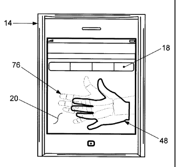
during authentication in a stationary position.
[0063] Figure 9 illustrates the outline image 48 and an initial position of an
image 76
of the hand 74 as shown on the display screen 20 while capturing biometric
data during
authentication. The hand image 76 in the initial position does not align with
the outline image
48. Consequently, the device 14 and the hand 74 are repositioned with respect
to each other
such that the hand image 76 shown on the display screen 20 better aligns with
the outline image
48 shown on the display screen 20.
[0064] Figure 10 illustrates the outline image 48 and a subsequent position of
the hand
image 76 as shown on the display screen 20 while capturing biometric data
during
authentication. After repositioning the device 14 and the hand 74 with respect
to each other,
the hand image 76 as shown on the display screen 20 has been rotated and
translated from the
initial position into the subsequent position. However, the subsequent
position of the hand
image 76 as shown on the display screen 20 does not adequately align with the
outline image
48 as shown on the display screen 20. Consequently, the device 14 and the hand
74 are further
repositioned with respect to each other such that the hand image 76 as shown
on the display
screen 20 is better aligned with the outline image 48 shown on the display
screen 20.
[0065] Figure 11 illustrates the outline image 48 and an aligned position of
the hand
image 76 as shown on the display screen 20 while capturing biometric data
during
16
CA 02764773 2012-01-19
authentication. After further repositioning the device 14 and the hand 74 with
respect to each
other, the hand image 76 has been further rotated and translated from the
subsequent position
such that the hand image 76 as shown on the display screen 20 approximately
aligns with the
outline image 48 shown on the display screen 20. When the hand image 76 shown
in the
display screen 20 approximately aligns with the outline image 48 shown on the
display screen
20, the operator captures hand biometric data by photographing the hand 74
with the device 14.
[0066] It should be appreciated that because the hand image76 aligns
approximately
with the outline image 48 during capture, hand biometric data captured during
authentication
is typically captured at a different, but similar, orientation as the hand
biometric data captured
during enrollment in the BAC system 12. Moreover, it should be understood that
the size of the
of the hand biometric data captured during authentication may typically be
different than the
size of the hand biometric data captured during enrollment. In the exemplary
embodiment, the
size of the hand biometric data image captured during authentication is
different than the size
of the outline image 48. Although the operator photographs the hand 74 with
the device 14 in
the exemplary embodiment, it should be understood that in other embodiments
the security
application may cause the device 14 to automatically photograph the hand 74.
In such other
embodiments, a photograph may be automatically taken when the hand image 76 is
within an
established tolerance of the outline image 48.
[0067] Figure 12 is a plan view of an exemplary authentication hand image 78
captured
by the device 14 during authentication. The authentication hand image 78
includes a center
point 80, the hand image 76, and biometric features 82 included in the hand
image 76. The
biometric features 82 are lines and wrinkles in the exemplary embodiment.
However, in other
embodiments the biometric features 82 may be any biometric feature including,
but not limited
to, ridge lines.
[0068] Figure 13 is a plan view of the exemplary authentication hand image 78
as
shown in Figure 12, further including an authentication region of interest 84.
The
authentication region of interest 84 is determined in a substantially
identical way as the
enrollment region of interest 30. The authentication region of interest 84
also includes the
second Cartesian coordinate system similar to the enrollment region of
interest 30. The
authentication region of interest 84 defines part of biometric data captured
during
17
CA 02764773 2012-01-19
authentication that is to be used for authentication. Because the
authentication region of
interest 84 is positioned on the hand image 76 to include mostly the palm
portion of the hand
image 76, palm biometric data is to be used for authentication in the
exemplary embodiment.
[0069] In order to facilitate approximately aligning differently oriented and
differently
sized images of the same biometric modality, during authentication the
authentication region
of interest 84 is manipulated to be approximately the same as the enrollment
region of interest
30. Specifically, the size of the authentication region of interest 84 is
increased or decreased
by a scale factor such that the size of the authentication region of interest
84 is approximately
the same as the size of the enrollment region of interest 30. Furthermore, the
authentication
region of interest 84 is rotated to have approximately the same orientation as
the enrollment
region of interest 30. It should be understood that the portion of the hand
image 76 within the
authentication region of interest 84 is manipulated in concert with the
authentication region of
interest 84 to have approximately the same size and orientation as the portion
of the hand 24
within the enrollment region of interest 30. By thus manipulating the
authentication region of
interest 84 and the portion of the hand image 76 within the authentication
region of interest 84,
the portion of the hand image 76 within the authentication region of interest
84 and the portion
of the hand 24 within the enrollment region of interest 30 may be
approximately aligned with
each other such that accurate authentication results may be generated. The
authentication
region of interest 84 and the enrollment region of interest 30 have the same
shape in the
exemplary embodiment. After the authentication region of interest 84 is
manipulated to have
approximately the same size and orientation as the enrollment region of
interest 30, a portion
of the palm image 76 within the authentication region of interest 84 is
converted to a gray scale
image.
[0070] Although the authentication region of interest 84 is manipulated to
have
approximately the same size and orientation as the enrollment region of
interest 30 in the
exemplary embodiment, in other embodiments the enrollment region of interest
30 may be
selected to be manipulated in a similar manner to have approximately the same
size and
orientation as the authentication region of interest 84.
[0071] Figure 14 is a plan view of a gray scale image 86 converted from the
hand image
76 within the authentication region of interest 84. Because the authentication
region of interest
18
CA 02764773 2012-01-19
84 is positioned on the hand image 76 to include mostly the palm portion of
the hand image 76,
the gray scale image 86 is also a gray scale image of the palm and is referred
to herein as a gray
scale palm image 86. The patch area 46 determined during enrollment in the BAC
system 12
is used to facilitate determining an optimum area of the gray scale palm image
86 that best
correlates to the patch area 46. Specifically, the patch area 46 is
incrementally positioned over
the entire gray scale palm image 86. In the exemplary embodiment, the patch
area 46 is
incrementally positioned over the entire gray scale palm image 86 one pixel
row or column at
a time. At each position, the patch area 46 is compared against the palm
biometric data of the
gray scale palm image 86 encompassed by the patch area 46 such that a
correlation score is
determined for each position. An area of the gray scale palm image 86
encompassed by the
patch area 46 is referred to herein as a matching area of the gray scale palm
image 86. The
correlation score indicates the correlation between the patch area 46 and a
corresponding
matching area of the gray scale palm image 86. Comparing the patch area 46
against the gray
scale palm image 86 and generating the correlation scores is referred to
herein as applying the
patch area 46 against the gray scale palm image 86. It should be understood
that the gray scale
palm image 86 is rotated through a series of angles and at the same time is
scaled through a
series of scale factors. For each rotation angle and scale factor combination,
the patch area 46
is applied against the gray scale palm image 86.
[0072] After calculating the correlation scores for each desired rotation
angle and scale
factor combination, the best correlation score is determined. Optimum
transformation
parameters are determined to be the rotation angle and the scale factor that
correspond to the
best correlation score, as well as the center point coordinates of the
matching area that
corresponds to the best correlation score. The matching area of the gray scale
palm image 86
that corresponds to the patch area 46 at the best correlation score is the
optimum area of the
gray scale palm image 86. The gray scale palm image 86 is then adjusted by the
rotation angle
and scale factor corresponding to the best correlation score, and the
coordinates of the
matching area in the gray scale palm image 86 are calculated using the second
Cartesian
coordinate system. The rotation angle and the scale factor of the optimum area
are also referred
to as the optimum rotation angle and the optimum scale factor. The optimum
rotation angle,
19
CA 02764773 2012-01-19
optimum scale factor and the coordinates of the optimum area, together
constitute an optimum
transformation parameter set.
[0073] It should be understood that the authentication region of interest 84
may also be
used to generate an authentication mask. Thus, by virtue of knowing the center
point
coordinates of the patch area 46 in the enrollment region of interest 30, the
optimum rotation
angle, the optimum scale factor, and the coordinates of the optimum area
center point, a
transformation necessary for approximately aligning the authentication region
of interest 84
with the enrollment region of interest 30 may be calculated. Likewise, the
transformation may
be calculated for approximately aligning the authentication mask with an
enrollment mask
generated during enrollment, and for approximately aligning the gray scale
palm image 86 with
an enrollment gray scale image generated during enrollment. Thus, the
transformation is
applied against the authentication mask to approximately align the
authentication and
enrollment masks. The transformation is also applied against the gray scale
palm image 86 to
approximately align the gray scale palm image 86 with the enrollment gray
scale image.
[0074] After aligning the authentication and enrollment masks, and aligning
the gray
scale palm image 86 and the enrollment gray scale image, a biometric template
is generated
from the aligned gray scale palm image 86. The authentication and enrollment
masks are
compared to determine a region common to both masks. Biometric template data
generated
from the aligned gray scale palm image 86 that is also within the common
region is used to
conduct a biometric authentication matching transaction. The common region may
also be
referred to as a region of agreement.
[0075] In the exemplary embodiment the authentication region of interest 84 is
rotated,
from its original orientation, through angles ranging from ten degrees
clockwise to ten degrees
counterclockwise. However, in other embodiments the authentication region of
interest 84
may be rotated by angles greater than ten degrees in either the clockwise or
counterclockwise
directions. Moreover, scale factors are applied to the authentication region
of interest 84 that
increase and decrease the size of the authentication region of interest 84 by
up to twenty
percent. However, in other embodiments other scale factors may be applied that
increase or
decrease the size of the authentication region of interest 84 by greater than
twenty percent.
CA 02764773 2012-01-19
[0076] It should be understood that the authentication mask and the gray scale
palm
image 86 each include the authentication region of interest 84. Thus, all
information or data
included in the authentication mask and the gray scale palm image 86 is
rotated and scaled as
described above for the authentication region of interest 84. Computations
relating to
determination of the optimum area are conducted in the second Cartesian
coordinate system.
[0077] Figure 15 is a plan view of an enrollment mask 88 generated from the
portion
of the hand 24 within the enrollment region of interest 30 during enrollment.
The enrollment
mask 88 includes shaded areas 90 that represent areas not containing valid
biometric data
within the enrollment region of interest 30. The mask 88 also includes another
area 92 that
represents areas containing valid biometric data within the enrollment region
of interest 30.
[0078] Figure 16 is a plan view of an authentication mask 94 generated from
the
portion of the hand image 76 within the authentication region of interest 84
during
authentication. The mask 94 includes shaded areas 96 that represent areas not
containing valid
biometric data within the authentication region of interest 84. The
authentication mask 94 also
includes another area 98 that represents areas containing valid biometric data
within the
authentication region of interest 84. During authentication, the enrollment
mask 88 and the
authentication mask 94 are compared to define a region common to both masks
88, 94.
Biometric data within the common region is used for matching during
authentication.
[0079] Figure 17 is a flowchart 100 illustrating an exemplary process for
enrolling
individuals in the BAC system 12. The enrolling process starts 102 by
activating a security
application stored in the device 14. The security application causes the
device 14 to display a
message prompting the operator to capture desired biometric data. The desired
biometric data
is the palm side of the right hand. Next, processing continues by capturing
biometric data 102,
in accordance with the message, from an enrollee with the device 14.
Specifically, in the
exemplary embodiment the biometric data is captured by photographing the
enrollee's hand
with the device 14. In the exemplary embodiment a single photograph is taken
during
enrollment. The device 14 continues processing by transmitting the captured
biometric data to
the BAC system 12.
[0080] Next, the BAC system 12 continues processing by generating 104 the
outline
image 48, determining 106 the enrollment region of interest 30, and generating
106 the
21
CA 02764773 2012-01-19
enrollment mask 88. The outline image 48, enrollment region of interest 30,
and enrollment
mask 88 are stored in the enrollment data record of the enrollee in the BAC
system 12.
[00811 Processing continues by determining 108 the patch area 46 within the
enrollment region of interest 30, processing the patch area 46 into a patch
area biometric
template, and storing the patch area biometric template in the enrollment data
record of the
enrollee. After determining 108 the patch area 46, processing continues by
extracting
biometric features 110 from the captured biometric data included in the
enrollment region of
interest 30, and processing the extracted biometric features into an
enrollment biometric
template. Because the enrollment region of interest 30 includes mostly the
palm of the hand,
the extracted biometric features are palm biometric features. Thus, the
enrollment biometric
template includes palm biometric data. The enrollment biometric template is
stored in the
enrollment data record of the enrollee. After extracting the biometric
features 110, a message
is communicated to, and displayed on, the device 14 notifying the user that
enrollment is
complete. Next, enrollment processing ends 112.
[0082] Figure 18 is a flowchart 114 illustrating an exemplary authentication
process
used by the AC system 10 for authenticating the identity of an individual. For
AC system 10,
the process starts 116 by activating the security application 118 in the
device 14 which initiates
the authentication process, when the individual desires to be authenticated.
It should be
appreciated that the individual may desire to be authenticated in many
different circumstances
including, but not limited to, when conducting any kind of transaction and
when requested by
security personnel to prove a claim of identity. After initiating the
authentication process, the
device 14 continues processing by requesting the outline image 48 from the BAC
system 12
and the BAC system 12 transmits the requested outline image 48 to the device
14 for use during
authentication.
[0083] Next, processing continues by displaying a message on the display
screen 20
prompting the operator of the device 14 to capture desired biometric data, and
displaying 120
the outline image 48 on the display screen 20 in a stationary position. It
should be understood
that the biometric modality data captured during authentication should be the
same as that
captured during enrollment. Thus, biometric data corresponding to the palm
side of a right
hand is captured during authentication. Accordingly, the outline image 48
corresponds to the
22
CA 02764773 2012-01-19
desired biometric data. Processing continues by positioning the desired
biometric data 122 of
the individual proximate to, and with respect to, the device 14 such that the
desired biometric
data appears as a desired biometric image in an initial position on the
display screen 20. Next,
the operator continues processing by monitoring the desired biometric image
shown on the
display screen 20 with respect to the outline image 48 shown on the display
screen 20, and
positioning the device 14 and the desired biometric data with respect to each
other, to better
align the outline and desired biometric images, when the initial position of
the desired
biometric image shown on the display screen 20 does not approximately align
with the outline
image 48 shown on the display screen 20. The device 14 and the desired
biometric data are
positioned with respect to each other until the desired biometric image shown
on the display
screen 20 approximately aligns with the outline image 48 shown on the display
screen 20.
After positioning the device 14 and the desired biometric data such that the
desired biometric
image shown on the display screen 20 approximately aligns with the outline
image 48 shown
on the display screen 20, processing continues by capturing the desired
biometric data.
Specifically, the operator continues processing by photographing the desired
biometric data
with the device 14. The device 14 continues processing by communicating the
captured
biometric data to the BAC system 12. In the exemplary embodiment a single
photograph is
taken during authentication. However, in other embodiments any number of
photographs may
be taken.
[0084] Although the desired biometric data is captured using the outline image
48
during authentication in the exemplary embodiment, it should be understood
that biometric
data may also be captured in a substantially identical manner during
enrollment if an outline
image 48 has been generated and stored in the BAC system 12 prior to
enrollment.
[0085] Next, processing continues by generating an authentication biometric
template
126 from the captured biometric data. Specifically, processing continues by
determining the
authentication region of interest 84 including the palm from the captured
biometric data, and
generating the gray scale palm image 86 and the authentication mask 96 for the
captured
biometric data. Processing continues by determining the optimum area within
the
authentication region of interest 84, and adjusting the scale and angle of the
authentication
region of interest 84 such that the adjusted authentication region of interest
84 approximately
23
CA 02764773 2012-01-19
aligns with the enrollment region of interest 30. The authentication and
enrollment masks, and
the gray scale palm image 86 and enrollment gray scale image are similarly
approximately
aligned with each other. Next, processing continues by extracting biometric
feature data from
the aligned gray scale palm image 86 and generating an authentication
biometric template 126
from the extracted biometric feature data. The aligned authentication and
enrollment masks
are compared to determine the region of agreement. Biometric feature data
included in the
authentication biometric template that is within the region of agreement is
used for conducting
a biometric verification matching transaction.
[0086] Processing continues by verifying the identity 128 of the individual by
comparing the biometric feature data included in the authentication biometric
template that is
within the region of agreement, against corresponding biometric feature data
included in the
enrollment biometric template and generating a matching score. After
generating the matching
score, processing continues by comparing the matching score against a
predetermined
threshold. When the matching score is at least equal to the predetermined
threshold the identity
of the individual is verified. A message is communicated to, and displayed on,
the device 14
notifying the operator of the verification, and processing continues by
conducting the
network-based transaction 130. Next, processing ends 132. However, when the
matching
score is less than the predetermined threshold, a message is communicated to,
and displayed
on, the device 14 notifying the operator that the individual was not verified,
and thus cannot
conduct the transaction. Next, processing ends 132.
[0087] Although a single outline image 48 is generated by and stored in the
BAC
system 12 in the exemplary embodiment, in other embodiments a plurality of
outline images
of different biometric modalities, for each individual, may be stored in the
BAC system 12. In
such other embodiments an outline image of the right hand and an outline image
of the left
hand may both be stored in the BAC system 12. Thus, prior to requesting the
outline image 48
during authentication, the operator may select one of the outline images to be
used for
authentication. Moreover, when the desired biometric data to be captured
includes biometric
data of different modalities, outline images corresponding to each different
modality may be
selected and presented in succession on the display screen 20. For example,
the left hand
24
CA 02764773 2012-01-19
image outline may be displayed first and the right hand image outline may be
shown on the
display screen 20 second.
[0088] In each embodiment, the above-described processes for capturing palm
biometric data and applying a transform to the captured palm biometric data,
facilitate reducing
the time and costs of accurately authenticating the identity of an individual
based on palm
biometric data captured while positioned freely in space. More specifically,
an outline image
is generated from hand biometric data captured with a device during enrollment
in an
authentication system. During authentication, the outline image appears on the
device display.
While aiming the device at a hand, an image of the hand also appears on the
device display.
The image of the hand may be positioned within the display to be approximately
aligned with
the outline image. When the image of the hand approximately aligns with the
outline image in
the device display, the hand is captured as biometric data by the device. A
region of interest
defines that palm biometric data included in the captured hand biometric data
is to be used
during authentication. A transform is calculated and is applied to the
captured palm biometric
data within the region of interest. The transform causes the captured palm
biometric data to
have approximately the same size and orientation as the palm biometric data
captured during
enrollment. As a result, biometric authentication of identities facilitates
reducing the time and
costs associated with authentication based on palm biometric data captured
while positioned
freely in space with a device readily available to the members of the general
public.
Accordingly, biometric authentication of identities is facilitated to be
enhanced in a cost
effective and reliable manner.
[0089] Exemplary embodiments of processes and systems that facilitate
convenient,
flexible and inexpensive biometric authentication based on palm biometric data
are described
herein. The processes are not limited to use with the specific computer system
embodiments
described herein, but rather, the processes can be utilized independently and
separately from
other processes described herein. Moreover, the invention is not limited to
the embodiments
of the processes and systems described above in detail. Rather, other
variations of the
processes may be utilized within the scope of the claims.
CA 02764773 2012-01-19
[0090] While the invention has been described in terms of various specific
embodiments, those skilled in the art will recognize that the invention can be
practiced with
modification within the scope of the claims.
26