Note: Descriptions are shown in the official language in which they were submitted.
CA 02764842 2012-01-20
2010P20968
1
Description
Method for the oscillation damping of a drive train in a wind
turbine, wind turbine and use of a braking device
The present invention relates to a method for the oscillation
damping of a drive train in a wind turbine, which drive train
connects a rotor to a generator. It further relates to such a
wind turbine and to the specific use of a braking device in
such a wind turbine.
In a wind turbine the kinetic energy of the wind is used for
the purpose of producing rotational movement in a rotor. This
rotational movement is transmitted via a drive train to a
generator which generates electrical energy from the
rotational energy.
Due to the transmission of force from the rotor to the
generator and due to further influences (see below), the drive
train and the wind turbine components surrounding it are
exposed to a multiplicity of forces, which result in
oscillations, i.e. vibrations in the drive train. In this
context, it is possible essentially to distinguish between
axial oscillations, which therefore propagate along the axis
or plurality of axes of the drive train, and radial
oscillations, which travel transversely relative to this axis
or axes. Such oscillations have a number of causes:
Firstly, external factors such as e.g. the wind speed, the
wind direction, the external temperature or turbulence play a
role. These factors of influence exert forces on the rotor,
not all of which act in an axial direction of the drive train
or the axis of the rotor. This results in mainly low-frequency
CA 02764842 2012-01-20
201OP20968
2
oscillations of up to approximately 10 Hz in the drive train.
Secondly, a complex overall system consisting of numerous
mechanically-interconnected components works during operation
of the wind turbine. For example, provision is often made for
a speed-transforming gear which transforms the relatively slow
rotation of the rotor or a first shaft of the drive train into
a faster rotation of a second shaft of the drive train.
Vibrations (i.e. torsional oscillations) automatically occur
in this gear due to the connection of the two drive train
components by means of toothed gearwheels or other elements
for the transmission of force. Torsional forces are also
transmitted from the gear onto the machine housing, i.e. onto
the internal structure of the cabin. Moreover, the gear also
produces axial oscillations, mainly in the high-frequency
range above 10 Hz.
Thirdly, pitch and yawing moments are produced by constraining
forces in connections between the cabin and components that
are mounted in the cabin. These constraining forces occur as a
result of the assembly, as a result of weight distribution,
and due to excitation of the natural frequencies of the drive
train. The pitch and yawing moments in the drive train produce
forces which act on the subfloor in the cabin of the wind
turbine and can damage this. The natural frequency of an
individual component is dependent on its weight and/or its
inertia in this case. By combining a system of components
during the assembly, new system characteristics and hence new
natural frequencies are produced.
Further oscillations can be induced as a result of a second
shaft being arranged, relative to the rotor, behind such a
speed-transforming gear, wherein a braking device is attached
CA 02764842 2012-01-20
201OP20968
3
to said second shaft and wherein said second shaft leads
towards the generator via a coupling in a posterior region of
the cabin. This coupling can be used to realize e.g. a
compensation of levels in the direction of the generator, this
being mounted lower or higher than the speed-transforming
gear. This coupling can also cause oscillations during
operation.
The oscillations and force effects in the region of the drive
train as summarized here in the form of an overview represent
a problem during operation of the wind turbine, because they
can significantly reduce the service life of the wind turbine
as a whole, or individual components thereof, and/or
permanently jeopardize their functionality. In particular,
high frequency oscillations above approximately 10 Hz can
cause significant damage at high amplitudes, primarily in the
gear, in the generator and to the cabin of the wind turbine.
They often continue along the whole drive train and can even
be amplified by the transformation in a gear. The VDI
specification VDI 3834, whose disclosure contents are
explicitly considered to be part of the present application,
sets forth the principles for the measurement and evaluation
of mechanical oscillations of wind turbines and their
components. It contains inter alia limits that should as far
as possible not be exceeded for loads caused by vibrations.
The cited oscillations and forces can be equalized by means of
various countermeasures, such that as far as possible no
constraining forces are transmitted from the gear or the drive
train onto the cabin. For example, the drive train is
currently mounted elastically on the housing of the cabin.
This mounting is effected e.g. by means of a three-point or
four-point mounting, which therefore comprises an elastic
CA 02764842 2012-01-20
'201OP20968
4
sprung connection between the subfloor and the drive train or
the speed-transforming gear at three or four points of the
drive train. In this context, the drive train can be fully or
partially surrounded at at least one point along its
longitudinal course, such that the drive train is stabilized
both laterally and upwards. Axially soft elastomers can be
used as rubber dampers for such bearings, e.g. in the form of
elastomer bushes which form the contact between the gear or a
drive train component and the respective bearing support or
the respective bearing ring.
A three-point mounting can comprise e.g. a main bearing and a
gear support: the main bearing features a bearing ring which
encloses a shaft of the drive train, i.e. a drive train
component. The main bearing therefore absorbs both axial and
radial forces. The gear support partially encloses a speed-
transforming gear from both sides, i.e. in a horizontal
direction and transversely relative to the axis of the drive
train. It is so designed as to be axially mobile and therefore
also absorbs torsional forces. This bearing is also used for
the equalization of both pitch and yawing moments. A four-
point mounting comprises a second bearing, which encompasses a
shaft of the drive train and therefore offers the advantage of
increased system stability due to additional absorption of
axial forces.
In addition to this passive equalization of oscillations by
means of bearings, provision can also be made for active
oscillation damping. To this end, provision can be made at the
bearings to exert active forces on the drive train or on other
wind turbine components connected to the drive train, which
active forces counteract the oscillations of the drive train
or the components connected to the drive train. However, such
CA 02764842 2012-01-20
2010P20968
active damping components require additional structural space
within the cabin of the wind turbine, as well as being
expensive to provide and maintenance-intensive. A further type
of active oscillation damping is effected by means of
converters, i.e. electronic components. By selectively
regulating a converter, it is possible to decrease or increase
loads from the generator side. Control of the converter for
the purpose of oscillation damping is therefore possible and
is currently also realized; however, it reduces the efficiency
of the energy production and also introduces an additional
factor of influence into the control of the converter.
Against this background, the present invention addresses the
problem of providing an improved means of oscillation damping,
which preferably involves in particular at most modest
additional installation or maintenance effort and/or
preferably results in increased damping efficiency, preferably
in particular offering greater accuracy of effect, in
comparison with purely passive oscillation damping.
This problem is solved by a method as claimed in claim 1 and a
wind turbine as claimed in claim 10, and by the use of a
braking device as claimed in claim 15.
Accordingly, the method of the type cited in the introduction
is inventively developed in that parameter values representing
an oscillation of the drive train are calculated and, on the
basis of the calculated parameter values, damping forces which
counteract the oscillation of the drive train are exerted in a
controlled manner on the drive train using a braking device.
Representative parameter values, e.g. frequencies and
amplitudes of an oscillation curve, can be derived from the
CA 02764842 2012-01-20
~010P20968
6
oscillations of the drive train. Conversely, it can also be
said that specific parameter values also represent the
oscillation characteristics of the drive train. Said parameter
values include inter alia the rotation speed and the rotation
moment of the drive train, wherein these can be used as a
basis for indirectly deducing which forces are produced by the
rotation of the drive train and could result in vibrations. In
particular, the oscillation characteristics of the drive train
are represented by those parameter values which are produced
directly from a vibration measurement, i.e. can be calculated
on the basis of a force measurement at the drive train, for
example.
The examination of such suitable parameters is used in the
context of the inventive method to draw conclusions relating
to the oscillation characteristics, and therefrom to derive
control instructions for an active oscillation damping device.
The braking device of the wind turbine is now used according
to the invention as an oscillation damping device or as part
thereof.
It is actually necessary to perform braking of the drive train
in various hazardous situations or critical operating
situations of the wind turbine. This applies in particular
when individual components of the wind turbine are out of
operation and further damages could be caused by the
rotational movement of the drive train. The same applies to
maintenance situations in which the wind turbine is maintained
by qualified staff. For this purpose, the qualified staff are
usually situated in the cabin of the wind turbine, where they
are hampered in the execution of their duties by the
rotational movement of the drive train and at the same time
seriously endangered by the enormous forces that are produced
CA 02764842 2012-01-20
'2010P20968
7
by this rotation. This means that as a rule the drive train
must be fully braked and locked in the context of maintenance,
in order to exclude any hazards or hindrances to the staff.
Complete or partial braking of the rotational movement of the
drive train is also necessary in the case of extreme wind
conditions, particularly storms or hurricanes. Only in this
way can it be ensured that no damage is sustained by
functional parts of the wind turbine, e.g. by the rotor or in
the generator, in the case of high wind speeds.
Accordingly, wind turbines used for industrial purposes today
to produce high levels of power, i.e. greater than 100 kW, are
normally always equipped with braking devices which allow both
partial and full braking of the rotational movement of the
drive train. Such braking devices usually consist of at least
one brake caliper comprising (in each case) at least one brake
pad, wherein the brake caliper spans a brake disc in such a
way that the brake pad can be pressed against the brake disc
and therefore brakes the brake disc in its movement. For this
purpose, the brake disc is firmly attached to a drive train
component of the drive train of the wind turbine. It therefore
rotates at the same rotation speed as the drive train
component. Conversely, when its rotational movement is braked
the drive train component is therefore braked at the same
time.
The invention therefore takes advantage of the fact that an
already existing functional components of the wind turbine,
namely the braking device, is now additionally used to perform
an active oscillation damping on the basis of the previously
mentioned control instructions that are derived from the
parameter values. In this case, the braking device can
CA 02764842 2012-01-20
2010P20968
8
function as an additional active damping device, but also as
the sole active damping device. Operation as a sole active
damping device ensures that no significant additional measures
are required for the installation of active oscillation
damping, since at least the mechanical main component of the
active oscillation damping, namely the braking device, is
already present. It is necessary merely to adapt the control
of the braking device, such that said braking device can be
used as a brake and as an active damping device concurrently.
When generating control instructions for the braking device,
it is possible in principle to distinguish between braking
instructions and damping instructions. In this case, braking
instructions are the control instructions that are used for
selective braking of the rotation of the drive train by the
braking device, whereas damping instructions are those control
instructions which are used for the active oscillation
damping. Coordination preferably takes place between the
braking instructions and the damping instructions, such that
interactions between braking and damping by the braking device
are reciprocally considered in advance and/or during operation
of the braking device. If the braking device is used to brake
the drive train as a result of a braking instruction, the
oscillation characteristics of the drive train could possibly
be affected. Damping instructions can therefore be derived,
these being correspondingly computed in advance or calculated
concurrently with the braking process, such that the braking
response of the braking device is immediately set during
operation so as to actively counteract an increase of
vibrations of the drive train. Conversely, active damping
actions on the drive train by the braking device also produce
a braking effect. If the drive train is to be braked in
parallel with the oscillation damping, this braking effect can
CA 02764842 2012-01-20
2010P20968
9
therefore be immediately included in the calculation of the
braking force to be applied, in the context of a coordinated
braking and damping process. Ultimately, by coordinating the
braking and damping process that is effected by the braking
device, the two types of control instructions can be
superimposed in order thus to derive a combined
braking/damping instruction. Such a superimposition can be
done electronically or by means of reciprocal influence of
forces from a plurality of mechanical actuators acting on the
braking device, or using a combination of these two
superimposition principles. In each case, the result of
generating a combined braking/damping instruction is the input
of a combined braking/damping force into the drive train.
The braking device is therefore used not only to perform
braking of the drive train, but also to produce a selective
and deliberate force effect for the purpose of oscillation
damping to counteract oscillations of the drive train. The
corresponding damping control instructions are therefore
derived from the parameter values relating to the oscillation
characteristics of the drive train. They control the braking
device in such a way that it introduces precisely set forces
into the drive train at specific defined times, wherein said
forces counteract the oscillation characteristics of the drive
train as derived from the parameter values.
The control instructions are generated in a control device
(i.e. a control unit) which is situated in the wind turbine
and/or connected to the wind turbine. Provision is therefore
made for a control device which regulates a braking force and
also actively counteracts vibrations or oscillations of at
least one drive train component of the drive train during
operation. The control device therefore performs a type of
CA 02764842 2012-01-20
2010P20968
"braking and damping program" which, from the parameter
measurements cited above, derives the control instructions
that are suitable for braking the drive train component in a
manner which counters the vibration frequency.
In addition to the active oscillation damping by the braking
device, provision can also be made for passive oscillation
damping, e.g. by means of corresponding mounting and
suspension. This is preferred in terms of providing dual
protection and increasing the damping effectiveness.
Correspondingly, a wind turbine according to the invention
comprises a rotor and a generator, these being connected
together via a drive train, and a braking device and a control
device. During operation, on the basis of parameter values
representing an oscillation of the drive train, the control
device in this case derives control instructions for exerting
damping forces on the drive train by means of the braking
device, wherein said damping forces counteract the oscillation
of the drive train in a controlled manner.
The control device is therefore designed in such a way that it
derives control instructions from the parameter values in
accordance with the inventive method, wherein said control
instructions are used for the selective control of the braking
device for oscillation damping.
The invention also comprises the use of a braking device for
the oscillation damping of a drive train in a wind turbine,
which drive train connects a rotor to a generator, wherein
parameter values representing an oscillation of the drive
train are calculated and, on the basis of the calculated
parameter values, damping forces are exerted in a controlled
CA 02764842 2012-01-20
201OP20968
11
manner on the drive train by means of the braking device,
wherein said damping forces counteract the oscillation of the
drive train.
Further particularly advantageous embodiments and developments
of the invention are derived from the dependent claims and
from the following description. In this case, the inventive
method and/or the inventive use can also be developed
according to the dependent claims relating to the wind turbine
and vice versa.
The control of the braking effect of braking devices in wind
turbines is currently transmitted by mechanical transmission
systems, hydraulically or pneumatically as a rule. Other
mechanical transmission systems are also conceivable, e.g.
connecting rods and/or toothed gears and/or cable control or
even via direct human intervention. The control of the braking
device is preferably done electronically. Electronic control
instructions are therefore generated before being transmitted
via transmission lines directly to an actuator where they can
be implemented by setting the position of the braking device
accordingly. This removes the need for indirect transmission,
e.g. by means of hydraulic transmission fluids with
corresponding susceptibility to error and maintenance and
longer response times. The electronic control and triggering
instead makes it possible also to achieve very finely
coordinated (e.g. pulsing) braking and damping effects,
wherein these can be achieved practically in real time and
specifically in the millisecond range. Using a purely
electronic regulating system, it is also possible to realize a
closed control circuit, wherein a control device for
electronically regulating a braking force is connected to (or
comprises) an analysis unit which processes the braking and/or
CA 02764842 2012-01-20
'2010P20968
12
damping measured signals from a measurement of the braking
and/or damping effect, such that the results of this signal
processing can be used by the control device to derive refined
control instructions for regulating a braking and/damping
force. Provision is therefore made here for a self-regulating
system which, despite the wear that inevitably occurs when
using braking systems, allows a braking and damping force to
be set precisely at all times, even during live operation of
the braking device.
A braking device comprising a wedge brake is preferably used
as a braking device, this being preferably controlled using
electronic regulation of the braking force. The wind turbine
according to the invention correspondingly features a braking
device which comprises a wedge brake, preferably an electronic
wedge brake.
The use of a wedge brake in the context of the braking device
has several critical advantages over the prior art, which
features conventional braking devices of the type described
above (pneumatically or hydraulically controlled caliper
brakes). In particular, it should be noted that less
expenditure of force is generally required for braking and/or
greater braking effect of the braking device can be achieved
using the same force. This means that a more effective damping
effect can also be achieved. Furthermore, a wedge brake can be
controlled very precisely and does not require a hydraulic or
pneumatic feed system, such that the above cited technical
problems relating to such systems can be avoided. In
particular, the filtering of transmission fluids and their
cooling are no longer required. Instead, the wedge brake
merely requires an actuator which moves the brake wedge in
such a way that a desired braking and/or damping effect is
CA 02764842 2012-01-20
2010P20968
13
produced, or in such a way that the transient braking and/or
damping effect is reduced. With reference to the oscillation
damping, in particular in connection with an electronic
control of a wedge brake, a damping effect is produced which
can be very finely tuned, and which can be exerted at
precisely the time when a maximum or minimum is expected in
the oscillation amplitude, such that maxima and/or minima can
be reduced in magnitude accordingly.
Wedge brakes are being installed in automobiles today for
trial purposes as a new type of brake system. In this context,
reference can be made to e.g. the article by Bernd Gombert /
Philipp Gutenberg: "Die elektronische Keilbremse" (The
Electronic Wedge Brake), Automobiltechnische Zeitschrift
11/08, volume 108, November 2006, pages 904-912. This article
also provides a comparison between conventional hydraulic
brake systems and an electronic wedge brake - for brake
systems in the field of automotive applications in each case.
The article states in summary that the electronic wedge brake
requires less expenditure of force and hence less energy for
the purpose of achieving the same braking force as other
automotive brake systems.
The use of wedge brakes in the context of wind turbines is not
known as yet. In addition to the above cited advantages, their
use in the field of wind turbines is also particularly
effective because the magnitudes of the forces occurring and
the heat that is potentially generated by frictional forces
are significantly greater than for applications in a passenger
vehicle. In contrast with motor vehicles, the braking in a
wind turbine must moreover take place fully automatically and
without human readjustment, whereas the actuator for the
operation of the brake in the automobile is effectively human,
CA 02764842 2012-01-20
~010P20968
14
specifically the driver. The same applies to the use of a
wedge brake for oscillation damping. Trials undertaken by the
inventor reveal that the operation of wedge brakes in the
field of wind turbines is so reliable that they are eminently
suitable for use there, wherein the advantages are even more
numerous in this large-scale application: Firstly, the
problems described above in relation to braking devices as per
the prior art are considerably more acute than for technical
applications having the magnitude of internal combustion
engines producing approximately 100 kW', since wind turbines of
contemporary design usually have a nominal power of more than
1 MW. Secondly, due to the size of the installation, a
considerably larger structural space is available for the
braking device, whereby it is effectively possible to use
wedge brakes of a simpler construction design and even
contribute to a space-saving effect. The brake discs in wind
turbines are correspondingly much larger, for example, and
therefore offer a larger contact surface for the brake wedge
of the wedge brake than is the case in the automobile engine
compartment. Thirdly, the role of the transmission of force
from the actuator to the actual brake is considerably more
important than in automotive applications. Finally, by virtue
of its susceptibility to control that is considerably more
precise, the wedge brake even offers the particularly
effective possibility of counteracting vibrations in a damping
manner as an additional effect.
In an embodiment that is particularly conducive to achieving
the objective, provision is made for the control instructions
for triggering the braking device for the purpose of
activating the damping forces to be derived as a function of
resonance frequencies of components of the wind turbine. To
this end, the resonance frequencies are calculated before the
CA 02764842 2012-01-20
2010P20968
wind turbine is started up, preferably by means of simulation
and/or measurements, and/or during live operation of the wind
turbine. A prototype of a wind turbine of the same structural
type or of an essentially similar structural type can be used
as a basis for measuring resonance frequencies before the wind
turbine is started up.
In this case, the resonance frequencies can comprise both a
dominant resonance frequency and its upper frequencies. They
can relate to individual components of the wind turbine, e.g.
a speed-transforming gear, the generator, the drive train or
the cabin, though the term "component" also encompasses the
complete wind turbine with its resonance frequencies. By means
of advance calculation and/or by means of calculating the
resonance frequencies during live operation of the turbine
(including at specific predefined test intervals), the
resonance frequencies can be identified and then counteracted
in a very selective manner. It is thus possible to prevent
"hunting" of individual components and/or of the complete wind
turbine system due to vibrations of the drive train, wherein
this has proven particularly effective in the prevention of
technical problems: it is precisely by preventing such hunting
that particularly pronounced movements can be prevented,
thereby allowing the wear and material fatigue to be actively
reduced to greatest effect.
In the operation of a wind turbine, a fundamental distinction
is made between thrust operating mode and reverse thrust
operating mode: In the case of reverse thrust operating mode,
the wind drives the rotor with such strength that forces from
the rotor act on and drive the drive train. The opposite
principle applies in the case of thrust operating mode, i.e.
the inertia of the rotating drive train (and the connected
CA 02764842 2012-01-20
201OP20968
16
rotating parts in the generator and possibly in a speed-
transforming gear) causes the rotor to be driven by the drive
train, such that the rotor effectively reaches a rotation
speed that is not achieved as a result of the prevailing wind,
but as a result of the forces from the drive train. By virtue
of its inert movement, the drive train continues the rotation
of the rotor even though insufficient wind is actually present
for this rotor movement. Therefore other forces also appear in
the drive train during thrust operation, particularly in a
speed-transforming gear if this is present.
In such speed-transforming gears, transmission currently takes
place between helical toothed gearwheels. Therefore at every
wheel position of two toothed gearwheels relative to each
other, a larger contact surface between the teeth is produced
than in the case of straight-toothed gearwheels. By virtue of
this sloping of the teeth, torsional forces are supported to
some extent both axially and radially. At the instant when the
reverse thrust operating mode of the wind turbine becomes a
thrust operating mode, different relationships of force occur
between the toothed gearwheels, since the other contact
surfaces (those not touching during the reverse thrust
operating mode) of the respective teeth now engage. The gear
and the drive train experience a hysteresis which is followed
by a transition to an inverted deformation of the drive train,
due to reversing torsional forces, and to an inverted pitch
and yawing moment of the drive train. During this transition
process, which is slower due to the hysteresis, mechanical
shocks and undesired oscillations are produced. Conversely, in
the case of a transition from thrust to reverse thrust
operating mode, such behavior is also evident in reverse,
though here the transition of forces usually occurs more
quickly: The rotor generally experiences an approximately
CA 02764842 2012-01-20
'2010P20968
17
continuous supply of energy from the wind, whereas in the
thrust operating mode only residual energy from the movement
of the drive train and the connected components is consumed.
The continuous supply of energy to the rotor also has the
effect that the system comprising rotor, drive train, gear and
generator stabilizes itself more quickly again and therefore'
vibrations are equalized relatively quickly - quasi
autonomously (supported by passive damping mechanisms if
applicable).
In the light of this, the inventor has recognized it to be
particularly advantageous if the damping forces are exerted
during a thrust operating mode of the drive train, and
preferably exclusively during a thrust operating mode of the
drive train. This also has the advantage that the efficiency
of the wind turbine is hardly reduced by the active damping,
more energy naturally being consumed if the active damping
takes place during the reverse thrust operating mode. In this
context, it is particularly advantageous if an identification
signal for detecting a transition from reverse thrust to
thrust operating mode is derived from the representative
parameter values. Likewise, an identification signal for
detecting a transition from thrust to reverse thrust operating
mode is preferably also derived. These identification signals
are subsequently preferably used to adapt the control
instructions to the braking device to the thrust or reverse
thrust operating mode respectively. Therefore a different
damping program runs according to whether the wind turbine is
in the reverse thrust operating mode or in the thrust
operating mode. Such a damping program can also specifically
provide for no active damping to be performed by the braking
device in the thrust operating mode, or for active damping in
the reverse thrust operating mode only in emergencies, e.g. if
CA 02764842 2012-01-20
201OP20968
18
a critical oscillation amplitude is reached at a resonance
frequency.
The state of the braking device itself can be used as an
influence factor as part of the oscillation damping using a
braking device. The brake shoes wear out and the brake disc of
the braking device experiences irregular deformations, wear
and deposits due to corrosion over time. In particular,
emergency braking can cause a brake disc to reach temperatures
of 4000 to 600 C. During cooling, which is not locally
uniform, the brake disc is therefore deformed by chemical and
physical effects. Asymmetries are produced. In the light of
this, provision is preferably made for varying an application
force on a brake disc of the braking device as a function of
deviations in the uniformity of the brake disc. In this case,
a parameter value and/or a measured signal representing the
degree of uniformity of the brake disc is sampled and used as
a basis for varying the control instructions for brake control
depending on the state of the brake disc.
The parameter values are preferably calculated on the basis of
sensor signals from a number of measuring sensors,
particularly preferably from vibration sensors for measuring
vibrations at components of the wind turbine and/or from force
sensors for measuring the damping forces that are exerted. The
parameter values can be derived from the sensor signals or the
sensor signals can be used directly as parameter values in
this case. The measuring sensors can be arranged outside the
wind turbine, for example, but are preferably arranged
therein, i.e. closer to the drive train oscillations to be
calculated and protected from external influences due to
weather and other external effects. In particular, the
measuring sensors are preferably located at the drive train
CA 02764842 2012-01-20
2010P20968
19
and/or at a wind turbine component that is connected to the
drive train, e.g. the generator, a speed-transforming gear or
the rotor. The measuring sensors can also comprise sensors for
measuring the rotation moment of the drive train and/or its
rotation speed, wherein such measuring sensors can also supply
e.g. parameter values from which it is possible to infer
whether the wind turbine is currently in the thrust operating
mode or in the reverse thrust operating mode. The measurement
of the exerted damping forces allows a feedback of parameter
values into the system, wherein said parameter values help to
show the effect of the damping measures. Other measuring
sensors (used additionally or alternatively) comprise sensors
for measuring the wind speed, wind direction and turbulence,
and for displacement measurement (e.g. for calculating the
axial displacement of the drive train and/or individual drive
train components or of the gear housing of a speed-
transforming gear). On the basis of the parameter values that
are derived from the respective measurement, it is then
possible to draw inferences regarding the oscillation
characteristics of the drive train.
The precise tuning of the damping forces can also be refined
by means of a precontrol. This means that control instructions
for exerting the damping forces are therefore generated on the
basis of precontrol signals that are derived from the
parameter values. Such precontrol signals are based on a
forecast of the oscillation development of the drive train on
the basis of parameter development values, i.e. values that
represent the development of values of an observed parameter
and/or a combination of parameters. This allows a relatively
satisfactory advance computation of future developments of the
oscillation of the drive train for a short time. On the basis
of parameter values for parameters such as rotation speeds,
CA 02764842 2012-01-20
201OP20968
rotation moments, state and concentricity of the brake disc,
desired values are calculated in accordance with a current
damping control instruction; the precontrol also receives
parameter values from the environment, such that a forecast of
the subsequent development of parameter values becomes
possible as an effect of the damping. This results in a
desired-state variable, which is fed into a return circuit and
compared with actual-state variables. The control does not
react immediately thereupon, but has expected values or guide
signals which were computed in advance as a basis and which
can then be repeatedly balanced with actual measured values
and/or parameter values in the context of fine tuning within a
closed control loop. The control becomes faster and more
accurate as a result.
Such a state estimate can be performed by means of a Kalman
filter, for example. Using this filter, it is possible to draw
inferences relating to the state of many of the systems
assigned to the technologies, sciences and management, merely
on the basis of erroneous observations. Simply stated, the
Kalman filter is used to remove the faults caused by measuring
devices. Both the mathematical structure of the underlying
dynamic system and that of the measurement distortions must be
known in this case.
It is fundamentally possible to derive control instructions
directly from calculated parameter values, e.g. from values
relating to a force measurement at the drive train, which
control instructions result in a force effect by means of the
braking device directly against the calculated forces. The
parameter values are preferably used for calculating a curve
of oscillations to be damped, and the damping forces are
preferably exerted in a manner that is diametrically opposed
CA 02764842 2012-01-20
2010P20968
21
in terms of direction and/or strength and/or frequency
(preferably in terms of all three of these characteristic
variables) to the calculated curve. Control instructions are
derived from the curve accordingly, and preferably have the
shape of a directly opposed curve.
A particularly preferred application area of the invention
relates to those wind turbines in which the drive train
comprises a first shaft and a second shaft as drive train
components, said shafts being connected together via a speed-
transforming gear. Active damping is particularly advantageous
here, because the speed-transforming gear generates additional
high-frequency oscillations as described above. In this case,
the braking device is preferably arranged in the region of the
second shaft, i.e. the shaft that leads from the speed-
transforming gear towards the generator. According to
experience, the greatest oscillation amplitudes along the
entire drive train occur here, and therefore application of
the active damping directly at the point of use of the braking
device can be particularly effective.
The speed-transforming gear translates the low rotation speed
of the first shaft into higher rotation speeds of the second
shaft, such that lighter generators can be driven and the
braking of the drive train can be more finely tuned. The
braking and damping of a shaft that is rotating faster (in
comparison with the rotation speed of the rotor and a first
shaft that is connected directly thereto) can be performed
more precisely because the braking effect (in absolute values
of the speed reduction) can be measured more easily than is
the case for slow rotating shafts. The same applies to the
damping effect with reference to absolute values of the
damping force effect. Moreover, the second shaft is therefore
CA 02764842 2012-01-20
201OP20968
22
less inert than the slow running first shaft.
In wind turbines featuring a wedge brake, the wedge brake
preferably comprises the following components:
- a brake disc which is connected to a drive train component
that is to be braked,
- a permanently installed retaining structure which is
arranged in the region of at least one flat side of the brake
disc and features a guide surface,
- a brake wedge that is mounted on the guide surface and has a
surface which faces towards the guide surface and whose shape
corresponds to that of the guide surface,
- an actuator which moves the brake wedge along the guide
surface during operation.
The brake wedge can be either directly or indirectly in
contact with the guide surface. For example, it can be
connected to the guide surface via rollers or slide along it
by means of a suitable sliding agent.
The brake wedge preferably comprises a brake pad, this being
attached to that side of the brake wedge which is opposite to
the guide surface in the direction of the brake disc, wherein
said brake pad is pressed onto the brake disc during the
braking operating mode.
Such an arrangement of the components of a wedge brake is easy
to assemble (and can possibly be installed as an upgrade in
existing braking devices) and straightforward to use. In
particular, the guiding of the brake wedge along the guide
surface has the consequence that the braking effect of the
wedge brake can be set in advance by the shape of brake wedge
and guide surface. For example, the shape of the guide surface
CA 02764842 2012-01-20
2010P20968
23
and/or of the brake wedge can be configured such that a
movement of the brake wedge does not produce a linear increase
in force, but an increase in force that is exponential or
conversely rises more slowly.
A wedge brake comprising the described components is
advantageously operated by an electric motor as an actuator,
wherein said electric motor is preferably regulated by an
electronic control device. It is therefore possible to use a
system that is as far as possible electronic electrical, in
which only the previously described components of the braking
device are mechanically embodied and the regulation takes
place entirely under electronic control.
Concerning the shape of the guide surface of the wedge brake,
a first basic alternative provides for said guide surface to
be plane and aligned obliquely relative to an axis of rotation
of the drive train component that is to be braked. In this
case, the guide surface preferably runs steeply towards a
brake disc that is to be braked. In a variation of this first
alternative, the guide surface is not plane, but describes a
course that rises or falls uniformly (preferably very
uniformly) in cross section in the manner of a crank. This
produces the above described effect of a non-linear
intensification of the braking force when the position of the
brake wedge is changed. The brake wedge preferably has a shape
which corresponds to this shape of the guide surface.
A second basic alternative consists of a guide surface and/or
a surface of the brake wedge in the form of a zigzag, e.g. in
the form of a W. Provision is preferably made for both the
guide surface and the surface of the brake wedge to be
similarly shaped in the form of a zigzag. Such a zigzag shape
CA 02764842 2012-01-20
'2010P20968
24
is illustrated e.g. in Figure 1 of the article by Roberts,
Richard et al.: "Testing the Mechatronic Wedge Brake" SAE
paper 2004-01-2766 and is described in the accompanying text.
The teaching from this description is correspondingly
incorporated into this patent application as teaching.
The zigzag shape does not necessarily have to be angular, but
can also be rounded. In other words, the guide surface and/or
the surface of the brake wedge features bumps and depressions,
such that the brake wedge can be moved against the guide
surface in two different directions, from an initial zero
point, in order to achieve an increase in braking force. This
alternative allows closer contact between the guide surface
and the brake wedge. As a result of this, a system can be
realized that is more compact, since it is inherently more
stable because the brake wedge cannot slip away completely
from the guide surface in one direction.
In a particularly advantageous development, a wind turbine
according to the invention comprises a plurality of braking
devices. In this case, a braking device can be designed and/or
controlled in such a way that it is used solely for braking
the drive train. Such a braking device is therefore based on a
simpler control model. Other braking devices can then be
designed and/or correspondingly controlled exclusively or
inter alia for oscillation damping. However, provision is
preferably made for at least two such braking devices, and
preferably in particular all braking devices, to be designed
and/or controlled in such a way that they can be used for
oscillation damping.
In the context of the invention, the use of a plurality of
braking devices offers the particular advantage that a
CA 02764842 2012-01-20
'201OP20968
plurality of braking devices can better relieve the load on
each other and hence experience less strain and wear during
operation, e.g. in the case of emergency braking. This results
in fewer irregularities in the brake discs and therefore
effectively allows greater precision when coordinating the
damping forces that can be exerted by each braking device.
Furthermore, the active damping effect can also be varied
locally, such that damping forces can be introduced into the
drive train in particular at those locations where damping is
particularly applicable. Therefore if the oscillation
amplitude is particularly high at a location, provision is
preferably made for using primarily those braking devices
which are closest to this location for the purpose of damping.
The braking devices can moreover be arranged differently, such
that e.g. one braking device introduces a damping force (and
braking force) from one side and another braking device from
above. As a consequence of this, oscillations having different
directions of oscillation can also be damped as effectively as
possible.
In the light of this, it is a further aim of the inventor for
at least two of the braking devices, and preferably all of the
braking devices, to be triggered independently of each other.
In this context, independent triggering means that different
control instructions are directed to the individual braking
devices. Nonetheless, these control instructions easily can -
indeed preferably do - form part of an overall context,
thereby allowing coordination of the control instructions at
the individual braking devices. This means that a "concerted"
damping action of the independent braking devices is possible,
wherein the damping forces accumulate in quantity and
direction to form a total damping force of all braking
devices, said total damping force corresponding to the damping
CA 02764842 2012-01-20
'2010P20968
26
effect that is desired by the control system.
It should also be noted that a braking device can additionally
be used for damping in the case of severe shock oscillations
when strong forces suddenly occur, e.g. in the event of a
power failure of the wind turbine. By virtue of the damping
braking action, the braking device prevents the cabin and the
tower of the wind turbine from moving against the wind, or
prevents the tower from twisting excessively (depending on the
wind direction). The effect of the rotor is similar to that of
an aircraft propeller in this case. A counter-moment is
indirectly obtained by the damping actions of the braking
device, and significantly reduces the movement of cabin and
tower and hence also the torsion of the latter.
The invention is described again in greater detail below with
reference to exemplary embodiments and to the appended
figures, in which the same components are denoted by identical
reference numerals in the different figures, and in which:
Figure 1 shows a side view of an embodiment of a wind turbine
according to the invention, the cabin of said wind turbine
being in an open state,
Figure 2 shows a greatly simplified schematic representation
of a wedge brake in cross section,
Figure 3 shows a detailed view from Figure 1 of parts of the
drive train and the braking device of the wind turbine,
Figure 4 shows a schematic block diagram depicting the flow of
an oscillation damping method according to an embodiment of
the invention,
CA 02764842 2012-01-20
2010P20968
27
Figure 5 shows a schematic block diagram depicting the flow of
a control process of the braking device with precontrol,
wherein such a control process can be used in the context of
an oscillation damping method according to the invention,
Figure 6 shows a schematic control curve in relation to
an oscillation curve of a drive train, wherein such a control
curve can be derived in the context of an oscillation damping
method according to the invention.
Figure 1 shows a wind turbine 13 according to an embodiment of
the invention. On its front side, which faces the wind, it
features a rotor 14 comprising a plurality of rotor blades 19.
These are connected to a hub 17. A first shaft 21 leads from
the hub 17 into the interior of the cabin 37 of the wind
turbine 13. Said first shaft is mounted in the cabin 37 via an
elastic main mounting 23 and a first yoke 25 and a second yoke
35 (whose positions can be adjusted by means of motors 29,
31).
A gear 33 converts the rotation of the first shaft 21 into a
rotation of a second shaft 44, wherein the second shaft 44 is
arranged on that side of the gear 33 which faces away from the
second shaft 21. The second shaft 44 leads to a generator 45,
in which current is obtained from the rotational energy of the
second shaft 44. A coupling 41 is used to couple the second
shaft 44 in or out, in order that in hazardous situations the
generator 45 can be decoupled from the rotation of the second
shaft 44. The first shaft 21 and the second shaft 44 together
form part of a drive train 22. The generator 45 is cooled by
means of a water cooler 49 and an additional ventilator 51. An
oil cooler can also be used instead of the water cooler 49.
CA 02764842 2012-01-20
'?01OP20968
28
The cabin 37 is rotatably mounted on a tower 27. A
meteorological sensor 47 is attached to the outside of the
cabin 37, providing meteorological data concerning e.g. the
wind situation, temperatures, cloud and visibility conditions,
etc.
Located in the region of the second shaft 44 is a servomotor
39, which engages with a toothed wheel 40 that is connected to
the second shaft 44. A brake disc 42 is also connected to the
second shaft 44 and is braked by a braking device 43.
The braking device 43 is so designed as to exert controlled
damping forces on the drive train 22, wherein said damping
counteract unwanted oscillations of the drive train. This
operation is described in greater detail with reference to the
Figures 3 to 6.
In order to demonstrate the operation of wedge brakes, Figure
2 shows a wedge brake 43 in a schematic representation as a
side view. It has a brake wedge 5, which can move over
floating rollers 9 along a guide plane 11 of a retaining
structure 10. A surface or bearing surface 12 of the brake
wedge 5 is aligned in the direction of the guide plane 11,
along which the floating rollers 9 are mounted. A brake pad 3
is situated on the opposite side of the brake wedge 5 to the
bearing surface 12, and is aligned in the direction of a brake
disc 42. The brake disc 42 rotates about an axis A, relative
to which the guide plane 11 is obliquely aligned, i.e. at an
angle unequal to 180 and unequal to 90 . This means that the
brake disc 42 rotates in the viewing direction of the
observer.
CA 02764842 2012-01-20
`2-OlOP20968
29
When the brake wedge 5 with the brake pad 3 lies against the
brake disc 42, a normal force F1 is present at the brake disc
42 and a frictional force F2 is present in a tangential
direction relative to the normal force F1. A combined braking
force F4 is produced in a triangle from the combination of
these two forces F1, F2. The braking of the brake disc 42 takes
place within this equilibrium of forces. If the brake wedge 5
is now pushed further in the direction of the axis A by an
actuator force F3, a stronger braking force F5 is produced
thereby. By moving the brake wedge 5 in the direction of the
axis of rotation A, it is therefore possible to achieve an
increase in the braking force of the wedge brake 43. Although
the braking force of the wedge brake 43 does not increase as
much as the actuator force F3 in this case, it is not necessary
to apply any additional force in order to hold the brake wedge
in position after the brake wedge 5 has been moved. Instead,
a new equilibrium of forces having a constant braking force F5
is produced. The required actuator force F3 is effectively
dependent on the friction properties of the contact between
the brake disc 42 and the brake pad 3. The wedge brake 43 has
reached its optimal braking point when no additional actuator
force F3 is required to move the brake wedge 5 further in the
direction of the axis A, in order thereby to achieve the
relevant desired braking force. A control device which
regulates the actuator force F3 effectively aims to ensure that
precisely this point is reached by achieving an equilibrium of
the forces.
A wedge brake is preferably used in the context of the
invention, though it is also possible to use other types of
braking devices in principle.
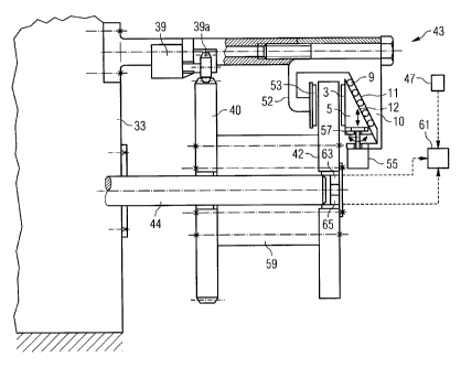
Figure 3 shows the region of the second shaft 44 and in
CA 02764842 2012-01-20
'2010P20968
particular the braking device 43 from Figure 1 in greater
detail. Starting from the gear 33, the second shaft 44 leads
in the direction of the generator 45 (not shown here). The
toothed wheel 40 is connected to the servomotor 39, which
engages with the toothed wheel 40 via a toothed wheel 39a. By
virtue of the servomotor 39, the rotational position of the
second shaft 44 can be adjusted in such a way that a locking
device 59 can catch in the toothed wheel 40 at a specified
locking position and hold it in place thus. The second shaft
44 is therefore held in place and cannot rotate, wherein this
applies at the same time indirectly via the gear 33 to the
first shaft 21. Arranged next in the direction of the
generator 45 are a brake disc 42 and two sensors 63, 65 which
measure both the rotation speed or rotation moment of the
second shaft 44 and hence indirectly its vibrations, i.e. the
detrimental oscillations that are to be damped in the context
of the invention.
As mentioned above, the braking device 43 for damping the
vibrations is realized as a wedge brake in the present
exemplary embodiment. This means that a brake wedge 5
according to the principle illustrated in Figure 2 is moved
upwards and downwards along floating rollers 9 over a guide
surface 51, in order to achieve the desired braking force F3,
F5 (cf. Figure 2) at the brake disc 42. In addition to the
brake pad 3 already shown in Figure 2, a second brake pad 53
is arranged on the opposite side to the brake pad 3 by virtue
of a brake caliper 52, such that the displacement of the brake
wedge 5 of the wedge brake 43 results in a type of clamping of
the brake disc 42 between the (first) brake pad 3 and the
second brake pad 53. An electrical servomotor 55 adjusts the
position of the brake wedge 5 of the wedge brake 43 via an
adjustment wheel 57, such that the desired braking force F3, F5
CA 02764842 2012-01-20
'2010P20968
31
is achieved.
The servomotor 55 is controlled by a control device 61 which
uses input data for this purpose, wherein said input data
comes from sensors and in particular the rotation sensor 63,
the vibration sensor 65 and the meteorological sensor 47, and
wherein said input data is used to derive control instructions
for inter alia the active damping of vibrations of the second
shaft 44. Said input data consists of parameter values
representing the oscillation characteristics of the drive
train.
The data from these sensors can also provide information
relating to the presence of hazardous situations which give
grounds for the rotation speed of the second shaft 44 or of
the entire drive train 22 to be reduced or brought to a
complete standstill. In effect, the control device 61 can
therefore set precisely the optimal transient braking and/or
damping force of the wedge brake 43 as a function of this and
other input data (e.g. measured data relating to the current
braking effect of the wedge brake 43).
Figure 4 shows a schematic flow diagram of an oscillation
damping method according to an embodiment of the invention. On
the basis of oscillations S of the drive train 22 (cf. Figures
1 and 3), representative parameter values P can be calculated
for these oscillations S. This can be done e.g. by means of
the sensors 63, 65 (cf. Figure 3). In a derivation step Ab,
these parameter values P are sued to derive control
instructions SB for oscillation damping of the oscillations S.
Further inputs can include information relating to resonance
frequencies Res of the drive train 22 or the wind turbine 13
or individual components thereof, i.e. information regarding
CA 02764842 2012-01-20
'2010P20968
32
the frequency ranges in which oscillations can cause
particular damage in the wind turbine 13. The control
instructions generated thus are forwarded to the braking
device 43, activation of which causes damping forces D to be
exerted on the drive train 22 and more specifically on the
second shaft 44.
Figure 5 shows a schematic block diagram relating to the flow
of a control process. Parameter values Pto that are requested
at a first time point are input into a precontrol VS. These
parameter values Pto comprise measured values for the rotation
speed and/or the rotation moment of the second shaft 44, the
rotation moment and the rotation speed of the rotor 14 and/or
of the first shaft 21, or the wind speed, for example. They
can also comprise measured values for pitch and yawing
moments, the axial displacement of the drive train 22 (or
individual components thereof), the disc state of the brake
disc 42 and the transient clamping force of the braking device
43 (i.e. the force that is exerted on the brake disc 42), etc.
On this basis, the precontrol VS derives precontrol signals
VSS which contain information relating to the approximate
braking force that is to be exerted by the braking device 43
at a second (subsequent) time point. These precontrol signals
VSS are fed into a control St which generates control
instructions SB therefrom and forwards these to the braking
device 43 for implementation.
In addition, the first parameter values Pto and precontrol
balancing signals VAS are forwarded to a balancing unit AE.
The precontrol balancing signals VAS contain information from
the precontrol VS, wherein said information indicates which
state inferences the precontrol VS has drawn from the first
parameter values Pto relating to the oscillation state of the
CA 02764842 2012-01-20
'2,01OP20968
33
drive train 22, in particular approximately which parameter
values are next expected after a damping action by the braking
device 43 has taken place. Similar second parameter values Pt,
are fed into the balancing unit AE at the second time point,
specifically after the first activation of the damping effect
of the braking device 43. The balancing unit AE compares the
second parameter values Pt, with the precontrol balancing
signals VAS and/or with the first parameter values Pto and
generates balancing data AD therefrom. It feeds this and the
second parameter values Pt, back to the precontrol VS, which
draws inferences therefrom in relation to the subsequent
development of the oscillations S in the drive train 22. The
balancing data AD is likewise forwarded to the control St,
such that the control St likewise draws inferences therefrom
in relation to the damping response that will be required in
the future.
This circuit is continuously repeated, whereby continuously
refined regulation of the damping force of the braking device
43 can be achieved in a closed loop.
Figure 6 shows a schematic control curve K2, the like of which
can be derived in the context of an oscillation damping method
according to the invention, in relation to a highly schematic
oscillation curve K1 of the drive train 22, said curves being
plotted over the time t (in seconds, without scaling). With
reference to the oscillation curve K1, the y-coordinate shows
the distance s (in mm, without scaling) that is covered by the
oscillations S. With reference to the control curve K2, it
shows the damping force D (in N, without scaling) that is
derived from the control instructions. The oscillation curve K1
is derived from parameter values P as explained above with
reference to Figure 4.
CA 02764842 2012-01-20
'201OP20968
34
The oscillation curve K1 is shown in a greatly simplified form
here as a sinusoidal curve with a fixed frequency and without
any irregularities. In practice, it generally deviates
markedly from such an ideally typical course, primarily
because a plurality of oscillation types (e.g. axial and
radial and torsional oscillations) are superimposed. This also
means that the corresponding control curve K2 will reflect this
complexity. The explanations relating to the oscillation
characteristics and control response are therefore likewise to
be understood as schematically simplified.
At the outset, at a time point to, the oscillation S is not yet
actively damped. In a critical frequency range, e.g. a
resonance frequency of the cabin 37, the oscillation curve K1
therefore has a relatively high first amplitude Amp,, which is
higher than an upper threshold value SW1. As a result of
reaching this threshold value SW1i an alarm state is triggered
which signifies that active oscillation damping is to be
initiated.
At a time point t1, i.e. directly after the critical frequency
and the high first amplitude Amp1 are detected, the oscillation
S is therefore actively counteracted by means of the braking
device 42. The control curve K2 in this case describes an
asymmetrically mirrored course along the t-axis (i.e. the
oscillation zero point of the oscillation curve K1), whereby
the damping force D is exerted precisely counter to the course
of the oscillation curve K,, wherein the level of the damping
force D increases to the same extent that the level of the
deviation of the drive train 22 from the oscillation zero
point as per oscillation curve K1 increases or decreases. The
amplitudes Amp2, Amp3r Amp4 of the oscillation curve K1r which
CA 02764842 2012-01-20
=2010P20968
are calculated after the time point t1r are therefore lower
than the first amplitude Amp1.
The amplitudes Amp2., Amp3, Amp4. of the damping curve K2
correspond to the amplitudes Amp2r Amp3r Amp4 of the
oscillation curve K1 to the extent that they decrease in
proportion to the amplitudes Amp2r Amp3, Amp4 of the
oscillation curve K1. By virtue of the damping, the resulting
level of the amplitude Amp4 lies below a lower threshold value
SW2. This means that the previously triggered alarm state can
now be cancelled. The active damping by means of the braking
device 43 is therefore stopped with effect from a time point
t2, i.e. directly after the lower threshold value SW2 is no
longer reached. The oscillation curve K1 continues along
desired paths with a lower amplitude until the upper threshold
value SW1 is reached again. The damping is therefore performed
solely by the passive dampers in the wind turbine 13, i.e. by
the main mounting 23, for example.
In conclusion, it is again noted that the foregoing detailed
description of the method, the wind turbine and its components
are merely exemplary embodiments which can be modified in all
variety of ways by a person skilled in the art without thereby
departing from the scope of the invention. Furthermore, use of
the indefinite article "a" or "an" does not exclude multiple
occurrence of the feature concerned. Moreover, "units" can
consist of one or more components, including components that
are so arranged as to be physically distributed.