Note: Descriptions are shown in the official language in which they were submitted.
CA 02764859 2016-11-08
CA 2764859
STEERABLE MEDICAL DELIVERY DEVICES AND METHODS OF USE
BACKGROUND
[0001] Delivery devices are used to deliver, or guide, medical devices or
instruments to a target
location within a subject. The delivery devices provide access to target
locations within the body where,
for example, diagnostic, therapeutic, and interventional procedures are
required. Access via these devices
is generally minimally invasive, and can be either percutaneous, or through
natural body orifices. The
access can require providing a guiding path through a body lumen, such as, for
example without
limitation, a blood vessel, an esophagus, a trachea and adjoining bronchia,
ducts, any portion of the gastro
intestinal tract, and the lymphatics. Once the delivery device has provided
access to the target location,
the delivery device is then used to guide the medical device or instrument to
perform the diagnostic,
therapeutic, or interventional procedure. An example of such a delivery device
is a guide catheter, which
may be delivered by steering it to its required destination, tracking it along
a previously delivered guide
wire, or both. The list of components being delivered for use percutaneously
is large and rapidly
growing.
[0002] Minimal outer dimensions of these delivery devices are important for
minimizing the injury
associated with delivery. Minimizing the wall thickness of the delivery device
provides additional space
for the medical device to be guided, while minimizing the injury associated
with entry into the subject and
the closure needed. Flexibility of the delivery device is important in
allowing the guiding device to track
or be steered to its target destination along tortuous paths while minimizing
injury to the intervening
tissues. The delivery device also needs to have compressive and tensile
properties sufficient to support its
delivery to the target site. When tracking around bends in the body, any kinks
created in the guiding
device can create an obstruction to the delivery of the medical device. When
used as a steerable device,
the distal end of the delivery device is preferably deflectable over a range
of bend radii and responsive to
the steering controls. The delivery device also should support torque
transmitted from the handle to the
distal region.
[0003] Once the delivery device is in place the delivery device preferably
also supports torque
around a distal bend such that the medical device may be rotated into position
while sustaining some
contact loads. Additionally, once in place the guiding device preferably is
sufficiently stiff to support and
guide the medical device to its target destination. The guiding device should
also remain stable and not
shift from one state of equilibrium to another either spontaneously or under
the influence of forces being
1
CA 02764859 2016-11-08
= CA 2764859
imparted to it from the delivery of thc medical device or its own control
mechanisms. As the delivery
device often travels down fluid-filled lumens such as, for example without
limitation, blood vessels, it
should additionally incorporate a seal against fluids impinging upon its
periphery and another at its distal
end which interfaces with the medical device to maintain a seal around the
delivery device.
[0004] There exists a need for improved steerable delivery devices and
guiding medical devices.
SUMMARY
[0005] One aspect of the disclosure is a steerable medical delivery device.
The device includes a
steerable portion comprising a first tubular member and a second tubular
member, wherein one of the first
and second tubular members is disposed within the other, wherein the first and
second tubular elements
are axially fixed relative to one another at a fixation location distal to the
steerable portion, and wherein
the first and second tubular members are axially movable relative to one
another along the steerable
portion to steer the steerable portion in a first direction, and wherein the
first tubular member is adapted to
preferentially bend in a first direction.
[0006] In some embodiments the second tubular member is substantially
uniform and is not adapted
to preferentially bend.
[0007] In some embodiments the first tubular member comprises at least one
slot therein to define a
first spine. The second tubular member can also include at least one slot
therein to define a second spine.
[0008] In some embodiments the first tubular member comprises a braided
material.
[0009] In some embodiments the first tubular member is disposed within the
second elongate tubular
member.
[0010] In some embodiments the first tubular member is adapted to be moved
axially relative to the
second tubular member to apply one of a compressive force and a tensile force
to the first tubular member
and the other of the compressive force and the tensile force to the second
tubular member to steer the
steerable portion in a first direction.
[0011] hi some embodiments the second tubular member is adapted to
preferentially bend in a
second direction, which can be substantially opposite the first direction.
[0012] In some embodiments the second elongate tubular element is a
floating tubular member.
[0013] One aspect of the disclosure is a steerable medical delivery device.
The device includes a
steerable portion comprising an outer tubular member and an inner tubular
member, wherein the inner
tubular member is disposed radially within the outer tubular member, wherein
the outer tubular member
includes at least one outer slot therein to define an outer spine, wherein the
inner tubular member includes
at least one inner slot therein to define an inner spine, the inner and outer
spines being offset relative to
2
CA 02764859 2016-11-08
= CA 2764859
one another, and wherein the outer tubular member and the inner tubular member
are axially movable
relative to one another along the steerable portion and are axially fixed
relative to one another at a
location distal to the steerable portion.
[0014] In some embodiments the outer tubular member comprises a plurality
of discontinuous slots
to define the outer spine.
[0015] In some embodiments the inner tubular member comprises a plurality
of discontinuous slots
to define the inner spine.
[0016] In some embodiments the inner and outer spines are offset
substantially 180 degrees from one
another.
[0017] In some embodiments the inner and outer spines are adapted to
receive one of a compressive
force and a tensile force to steer the steerable portion of the delivery
device. The inner spine can be
adapted to receive a compressive force thereto and the outer spine can be
adapted to receive a tensile
force thereto to steer the steerable portion of the delivery device in a first
direction. Alternatively, the
inner spine is adapted to receive a tensile force thereto and the inner spine
is adapted to receive a
compressive force thereto to steer the steerable portion of the delivery
device in a first direction.
[0018] In some embodiments the inner and outer slots are in substantial
alignment relative to a
longitudinal axis of the steerable portion when the steerable portion is in a
straightened configuration.
The inner and outer slots can be substantially perpendicular to the
longitudinal axis of the steerable
portion when the steerable portion is in a straightened configuration.
[0019] In some embodiments the inner and outer slots are not in alignment
relative to a longitudinal
axis of the steerable portion when the steerable portion is in a straightened
configuration.
[0020] In some embodiments at least one of the outer slot and the inner
slot includes a first
interlocking element and a second interlocking element each adapted to allow
relative movement
therebetween when in a first configuration and each further adapted to prevent
movement therebetween
when in a second configuration.
100211 In some embodiments the delivery device further comprises a fixation
element distal to the
steerable portion adapted to prevent axial movement between the outer tubular
element and the inner
tubular element.
[0022] In some embodiments the inner tubular member has an inner surface,
and wherein the inner
surface is sized to allow a medical device to be advanced therethrough.
[0023] One aspect of the disclosure is a method of steering a medical
delivery device. The method
includes a steerable medical delivery device comprising a steerable portion
with an outer tubular member
and an inner tubular member, wherein the outer tubular member includes at
least one outer slot therein to
3
CA 2764859
define an outer spine, and wherein the inner tubular members includes at least
one inner slot therein to
define an inner spine, the inner and outer spines being offset relative to one
another. The method
includes applying a compressive force to one of the inner and outer spines and
a tensile force to the
other of the inner and outer spines to steer the steerable portion from a
first configuration to a second
configuration. The method also includes preventing relative axial movement of
the inner tubular
member and outer tubular member at a location distal to the steerable portion
while the steerable portion
is being steered.
[00241 In some embodiments the applying step comprises applying the
compressive force to the
inner spine, and wherein applying the compressive force to the inner spine
causes the tensile force to be
applied to the outer spine to steer the steerable portion. Applying the
compressive force to inner spine
can include moving the inner tubular member distally relative to the outer
tubular member.
[00251 In some embodiments the applying step comprises applying the tensile
force to the inner
spine, and wherein applying the tensile force to the inner spine causes the
compressive force to be
applied to the outer spine to steer the steerable portion. Applying the
tensile force to the inner spine can
include moving the inner tubular member proximally relative to the outer
tubular member.
[00261 In some embodiments the applying step comprises applying the
compressive force to the
outer spine, and wherein applying the compressive force to the outer spine
causes the tensile force to be
applied to the inner spine to steer the steerable portion. Applying the
compressive force to the outer
spine can include moving the outer spine distally relative to the inner
tubular member.
100271 In some embodiments the applying step comprises applying the tensile
force to the outer
spine, and wherein applying the tensile force to the outer spine causes the
compressive force to be
applied to the inner spine to steer the steerable portion. Applying the
tensile force to the outer spine can
include moving the outer tubular element proximally relative to the inner
tubular member.
[0028] One aspect of the disclosure is a steerable medical delivery device.
The medical device
includes an elongate member comprising a steerable portion adapted to be
steered in a first direction,
and a floating element disposed within the steerable portion, wherein the
floating element is axially
fixed relative to the elongate member at a location proximal to the steerable
portion, and is not axially
fixed relative to the elongate member along the steerable portion.
[0029] In some embodiments the elongate member is a catheter.
[0030] In some embodiments the elongate member comprises an inner tubular
member with an
inner slot therein to define a first spine, and an outer tubular member with
an outer slot therein to define
an outer spine, wherein the spines are offset from one another.
4
CA 2764859 2017-10-05
CA 2764859
100311 Also disclosed is a steerable medical delivery device, comprising: a
steerable portion
comprising a first tubular member and a second tubular member, wherein one of
the first and second
tubular members is disposed within the other, wherein the first and second
tubular elements are axially
fixed relative to one another at a fixation location distal to the steerable
portion, and wherein the first
and second tubular members are axially movable relative to one another along
the steerable portion to
steer the steerable portion in a first direction, and wherein the first
tubular member is adapted to
preferentially bend in a first direction.
[0032J Also disclosed is a steerable medical delivery device, comprising: a
steerable portion
comprising an outer tubular member and an inner tubular member, wherein the
inner tubular member is
disposed radially within the outer tubular member, wherein the outer tubular
member includes at least
one outer slot therein to define an outer spine, wherein the inner tubular
member includes at least one
inner slot therein to define an inner spine, the inner and outer spines being
offset relative to one another,
and wherein the outer tubular member and the inner tubular member are axially
movable relative to one
another along the steerable portion and are axially fixed relative to one
another at a location distal to the
steerable portion.
[0032A] Also disclosed is a method of steering a medical delivery device,
comprising: a steerable
medical delivery device comprising a steerable portion with an outer tubular
member and an inner
tubular member, wherein the outer tubular member includes at least one outer
slot therein to define an
outer spine, and wherein the inner tubular members includes at least one inner
slot therein to define an
inner spine, the inner and outer spines being offset relative to one another;
applying a compressive force
to one of the inner and outer spines and a tensile force to the other of the
inner and outer spines to steer
the steerable portion from a first configuration to a second configuration;
and preventing relative axial
movement of the inner tubular member and outer tubular member at a location
distal to the steerable
portion while the steerable portion is being steered.
[0032B] Also disclosed is a steerable medical delivery device, comprising:
an elongate member
comprising a steerable portion adapted to be steered in a first direction; and
a floating element disposed
within the steerable portion, wherein the floating element is axially fixed
relative to the elongate
member at a location proximal to the steerable portion, and is not axially
fixed relative to the elongate
member along the steerable portion.
10032C] Also disclosed is a lockable medical delivery guide, comprising: a
first bead and a second
bead, each of which comprises a control wire bore therethrough; a control wire
passing through the
control wire bores, wherein the control wire is secured to the second bead and
is not secured to the first
bead, wherein the first bead and the second bead are movable relative to one
another in a delivery
4a
CA 2764859 2017-10-05
CA 2764859
configuration, and are adapted to be locked together in a locked configuration
upon the application of an
actuation force to at least one of the first bead and the control wire.
[0032D] The invention disclosed and claimed herein pertains to a steerable
medical delivery device,
comprising: a steerable portion comprising: a first tubular member comprising
a first flexible polymeric
tubular member, the first tubular member configured to preferentially bend;
and a second tubular member
comprising a second flexible polymeric tubular member, the second tubular
member configured to
preferentially bend, wherein the first tubular member is disposed within the
second tubular member; wherein
the first and second tubular members are permanently axially fixed relative to
one another at a fixation location
distal to the steerable portion, and wherein an external controller is
configured to axially move at least one of
the first and second tubular members relative to the other at a location
proximal to the steerable portion to
cause relative axial movement between the first and second tubular members
along the steerable portion to
steer the steerable portion in a first direction.
[0032E] Particular embodiments of the invention disclosed and claimed
herein pertain to a steerable
medical delivery device, comprising: a steerable portion comprising: a first
tubular member comprising a first
flexible polymeric tubular member, the first tubular member configured to
preferentially bend; and a second
tubular member comprising a second flexible polymeric tubular member, the
second tubular member
configured to preferentially bend, wherein the first tubular member is
disposed within the second tubular
member; wherein the first and second tubular members are permanently axially
fixed relative to one another at
a fixation location distal to the steerable portion, and wherein an external
controller is configured to axially
move at least one of the first and second tubular members relative to the
other at a location proximal to the
steerable portion to put one of the first and second tubular members in
tension and the other of the first and
second tubular members in compression to steer the steerable portion.
BRIEF DESCRIPTION OF THE DRAWINGS
[0033] The novel features of the invention are set forth with particularity
in the disclosure herein. A
better understanding of the features and advantages of the present invention
will be obtained by reference to
the following detailed description that sets forth illustrative embodiments,
in which the principles of the
disclosure are utilized, and the accompanying drawings of which:
[0034] FIG. 1 is a perspective view of a steerable portion of a steerable
medical delivery device.
[0035] FIGS. 2a, 2b, and 2c illustrate steering of exemplary steerable
portions of steerable medical
delivery devices
[0036] FIG. 3 illustrates a flattened view showing an exemplary slot
pattern for use in a steerable portion
of a delivery device.
[0037] FIG. 4 illustrates a flattened view showing an exemplary slot
pattern for use in a steerable portion
of a delivery device.
[0038] FIG. 5 illustrates a flattened view showing an exemplary slot
pattern for use in a steerable portion
of a delivery device.
4b
CA 2764859 2018-07-26
CA 02764859 2011-12-08
WO 2010/151698
PCT/US2010/039865
[0039] FIG. 6 illustrates a flattened view showing an exemplary slot
pattern for use in a steerable
portion of a delivery device.
[0040] FIGS. 7a and 7b illustrate flattened views showing exemplary slot
patterns for use in a
steerable portion of a delivery device.
[0041] FIG. 8 illustrates an exemplary steerable portion including an outer
slotted tubular member
and an inner slotted tubular member, with an intermediate tubular element
therebetween.
[0042] FIG. 9 illustrates an exemplary steerable portion including an outer
slotted tubular member
and an inner non-slotted tubular member.
[0043] FIG. 10 illustrates an exemplary steerable portion including an
inner slotted tubular member
and outer non-slotted tubular member.
[0044] FIG. lla is a representation of a pattern for use in a steerable
portion capable of being cut
from a tube or created by winding a ribbon into a tube.
[0045] FIG. llb illustrates a section of a ribbon for use in the tube of
FIG. lla.
[0046] FIGS. 12a and 12b are different views of a groove pattern for use in
a steerable portion.
[0047] FIGS. 13a, 13b, and 13c are various views of a cut pattern for use
in a guide catheter
[0048] FIG. 14 illustrates an outer guide member and a delivery device
therein.
[0049] FIG. 15 illustrates a discontinuous cut pattern for use on a tubular
member that is most
steerable in compression.
[0050] FIGS. 16a and 16b illustrate a portion of a tubular member formed
with the cut pattern from
FIG. 15, while FIG. 16c illustrates compressive and tensile forces acting
thereon.
[0051] FIG. 17 is a graph illustrating Force v. Displacement behavior
associated with the application
of loads or displacements at various points around the tubular member shown in
FIGS. 15-16c.
[0052] FIG. 18 illustrates a continuous cut pattern for use on a tubular
member that is most steerable
in tension.
[0053] FIG. 19 illustrates a discontinuous cut pattern for use on a tubular
member most steerable in
tension.
[0054] FIG. 20 illustrates a continuous cut pattern for use on a tubular
member most deflectable in
tension.
[0055] FIG. 21 illustrates a discontinuous cut pattern for use on a tubular
member with a
substantially straight, continuous spine.
[0056] FIG. 22 illustrates a discontinuous cut pattern for use on a tubular
member with a helical,
continuous spine.
[0057] FIG. 23 is a flattened view of an exemplary tubular member with more
than one spines.
[0058] FIG. 24 is a flattened view of an exemplary member with a single
substantially straight spine.
[0059] FIG. 25 illustrates a flattened portion of an exemplary tubular
member. The slots create a
relatively neutral pattern.
[0060] FIG. 26 illustrates a flattened portion of an exemplary tubular
member including interlocking
features with complimentary curved surfaces that are adapted to support
rotation of the tubular member.
CA 02764859 2011-12-08
WO 2010/151698
PCT/US2010/039865
[0061] FIG. 27 illustrates an exemplary steerable delivery device including
a floating tubular
member disposed therein.
[0062] FIG. 28 illustrates an exemplary steerable medical delivery system.
[0063] FIGS. 29A and 29B illustrate an exemplary embodiment of a lockable
portion of a guiding
device.
[0064] FIGS. 30A-30H illustrate exemplary beads that can be used in a
lockable guiding device.
DETAILED DESCRIPTION OF THE INVENTION
[0065] The disclosure relates generally to steerable delivery devices,
which may be considered
steerable guide devices, and their methods of use. The steerable delivery
devices can be used to deliver,
or guide, any type of suitable medical device or instrument therethrough to a
location within a patient's
body. For example, the steerable delivery devices can be used to deliver, or
guide, a medical device into
bodily lumens such as, for example without limitation, a blood vessel, an
esophagus, a trachea and
possibly adjoining bronchia, any portion of the gastrointestinal tract, an
abdominal cavity, a thoracic
cavity, various other ducts within the body, and the lymphatics. Once the
steerable delivery device has
gained access to a target location within the subject, the medical device or
instrument is delivered, or
guided, to the target location to carry out the medical intervention.
Steerable delivery devices described
herein can be tracked along a previously delivered guide wire.
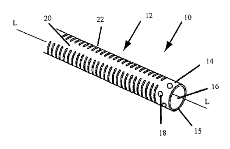
[0066] Figure 1 is a perspective view of a distal portion of an exemplary
steerable delivery device.
Steerable device 10 includes steerable portion 12 and has distal end 15.
Steerable portion 12 includes an
outer tubular member 14 and inner tubular member 16. Outer tubular member 14
has an inner surface
defining a lumen therein, and inner tubular member 14 is sized to be disposed
within the inner lumen of
outer tubular member 14. Outer tubular member 14 and inner tubular member 16
are axially fixed
relative to one another at fixation location 18 along the length of steerable
device 10. That is, at fixation
location 18, the inner and outer tubular members are not adapted to move
distally or proximally relative to
one another. Fixation location 18 is located distal to steerable portion 12.
At locations proximal to
fixation location 18, inner tubular member 16 and outer tubular member 14 are
axially movable relative to
one another. That is, along steerable portion 12, inner tubular member 16 and
outer tubular member 14
are adapted to move axially relative to another. Outer tubular member 14 has
slots 22 formed therein to
define spine 20. Spine 20 extends along a length of steerable portion 12.
Slots 22 are shown substantially
perpendicular to the longitudinal axis "L" of steerable portion 12, when
steerable portion 12 is in a
straightened configuration as shown in Figure 1. Inner tubular member 16 also
has slots formed therein
(not shown) in the steerable portion to define a spine (not shown).
[0067] Figures 2a and 2b illustrate an exemplary embodiment of a steerable
delivery device.
Steerable device 30 has a distal end 37 and includes outer tubular element 34
and inner tubular element 36
which are axially immovable relative to one another at fixation location 38,
but are axially movable
proximal to fixation location 38. Outer tubular element 34 includes a
plurality of slots 42 formed therein
to define spine 40. Inner tubular element 36 also includes a plurality of
slots formed therein (not shown)
to define a spine (not shown). In Figures 2a and 2b, the spines are disposed
substantially 180 degrees
6
CA 02764859 2011-12-08
WO 2010/151698
PCT/US2010/039865
apart from one another. Figure 2a illustrates steerable portion 32 deflected,
or steered, into a first bent
configuration, while Figure 2b illustrates steerable portion 32 steered into a
second bent configuration
different than the first bent configuration. To steer the steerable portion
into the configuration shown in
Figure 2a, a proximal portion of outer tubular member 34 is moved axially, and
specifically proximally,
relative to inner tubular member 36, while the tubular elements 34 and 36 are
axially fixed relative to one
another at fixation location 38. This can be accomplished by pulling outer
tubular member 23 in a
proximal "P" direction while maintaining the position of inner tubular member
36, by pushing inner
tubular member 36 in a distal "D" direction while maintaining the position of
outer tubular member, or by
a combination thereof. The relative axial movement of the inner and outer
tubular members as shown in
Figure 2a applies substantially opposing compressive and tensile forces to the
spines of the tubular
members, thus deflecting, or steering, the device in the direction of spine 40
of outer tubular member 34,
as is shown in Figure 2a. Figure 2b illustrates a step of steering device 30
in the substantially opposite
direction from that shown in Figure 2a. To steer device 30 into the
configuration shown in Figure 2b,
inner tubular member is moved proximally relative to outer tubular member 34.
This can be performed by
moving the outer tubular member distally, moving the inner tubular member
proximally, or a combination
thereof. This relative axial movement applies substantially opposing
compressive and tensile forces to
the spines in steerable portion 32 of device 30, thereby deflecting the device
in a direction substantially
opposite that of spine 40 of outer tubular member 34.
[0068] Figure 2c shows a sectional view of the steerable portion from
Figure 2b, including optional
floating tubular member 505 disposed within inner tubular member 504.
Steerable portion 500 includes
inner tubular member 504 and outer tubular member 502. Inner tubular member
504 has interrupted slots
512 formed therein to define spine 506. Outer tubular member 502 has
interrupted slots 510 formed
therein to define spine 508. The steerable portion is bent along the axis of
spine 506. Spine 508 and spine
506 are substantially 180 degrees apart from one another (i.e., they are on
substantially opposite sides of
steerable portion 500).
[0069] To steer steerable portion 500 into the configuration shown in
Figure 2c (also shown in
Figure 2b), inner tubular member 504 is pulled in the proximal direction
relative to outer tubular member
502, as is illustrated in Figure 2h. Pulling on the inner member 504 applies a
tensile force to inner spine
506. Because inner and outer tubular members 504 and 502 are axially fixed
relative to one another at a
location distal to the steerable portion, pulling on inner member 504 relative
to outer tubular member 502
results in a compressive force applied to the distal end of the steerable
portion of outer tubular member
502. The compressive force begins to compress slots 510 on outer tubular
member 502. Compression of
outer slots 510 causes outer tubular member to bend in the direction shown in
Figure 2c, and the bending
stops when inner slots 510 are closed. Thus, outer slots 510 limit the degree
of the bend of steerable
portion 500. The same type of bending that is shown in Figures 2b and 2c would
occur if outer tubular
element 502 were pushed distally relative to inner tubular member 504.
[0070] If outer tubular member 502 were pulled proximally relative to inner
tubular member 504 (or
if inner tubular member 504 were pushed distally relative to outer tubular
member 502), steerable portion
7
CA 02764859 2011-12-08
WO 2010/151698
PCT/US2010/039865
500 would bend in the manner shown in Figure 2a. The degree of the bend would
be limited by inner
slots 512.
[0071] Figure 2c illustrates an embodiment of a medical device including a
floating tubular member,
which may be referred to herein as a floating liner. In general, a floating
liner is disposed within an outer
structure. In the exemplary embodiment in Figure 2c, the outer structure
includes the inner and outer
tubular members. The outer structure generally provides structural and
mechanical properties for the
delivery device, and the floating liner provides lubricity for a medical
device or instrument to be
advanced therethrough. A floating liner is generally impermeable as well. A
floating liner "floats" with a
portion of the outer structure. That is, the floating liner is not fixed to a
portion of the outer structure in
which it floats. In the exemplary embodiment in Figures 2c, the floating liner
floats within the steerable
portion (i.e., is not attached to the steerable portion). In general, a
floating liner is attached to the outer
structure at a location proximal to the steerable or bendable portion of the
device. For example, in the
embodiment in Figure 2C, the floating liner is attached to the outer structure
at a location proximal to the
steerable portion. A floating liner doesn't impede the ability of the outer
structure to move as it is steered,
bent, actuated, receives forces applied thereto, etc.
[0072] In some embodiments the floating liner is a lubricious polymer tube.
In some embodiments
the floating liner includes wire windings and/or axially laid wires.
[0073] The outer structure in which the floating liner floats can be any
suitable tubular member. For
example, the outer structure can be a catheter, guiding device, a steerable
device, etc. In some
embodiments the outer structure has a neutral bending preference but is not
intended to be steered. In this
embodiment the outer structure provides axial and radial stiffness thereby
limiting the likelihood of kinks
while the floating liner provides lubricity and is additionally restrained
from kinking by the outer
structure.
[0074] Figures 2a and 2b also show proximal portion 35 of device 30, which
is proximal to steerable
portion 32, having a substantially neutral portion designed to have no
preferential bending axis while at
the same time transmitting axial force and torque applied at a proximal end of
the device (not shown).
[0075] In some embodiments, the inner and outer tubular members are adapted
to have opposing
compressive and tensile loads applied thereto to steer the steerable portion.
In some embodiments at least
one of the tubular members has a neutral bending axis. A neutral bending axis,
as used herein, generally
refers to an axis of the tubular member along which there is substantially no
axial displacement in
response to a compressive and/or tensile force applied thereto. Axial
displacement along the neutral
bending axis, in response to a compressive and/or tensile force applied
thereto, is less than axial
displacement of structures elsewhere in the tubular member. In particular,
axial displacement along the
neutral bending axis is minimal relative to axial displacement of structures
elsewhere in the tubular
member. Examples of a neutral bending axis include spine 382 in Figure 21 and
spines 412 and 414 in
Figure 23.
[0076] In some embodiments at least one of the tubular members is adapted
to offset the neutral
bending axis relative to the opposite tubular member. The neutral bending axes
of the tubular members
8
CA 02764859 2011-12-08
WO 2010/151698
PCT/US2010/039865
can be offset to be approximately tangent to opposite sides of the opposing
members, making the neutral
bending axis offset equal to the diameter of the device, thus providing the
highest possible bending
leverage ratio for a given device diameter.
[0077] The tubular members described herein may exhibit preferential or
neutral bending behavior.
Neutral bending behavior implies that the displacement for a given radially
applied load (from the edge of
the tubular member through the longitudinal axis of the tubular member) will
be independent of the radial
angle from which the load was applied. In contrast, in a non-neutral structure
the displacement associated
with a radial load will change as a function of the radial angle. An exemplary
tubular member tending
towards neutral bending behavior is shown in Figure 25 or the uninterrupted
spiral pattern of Figure 25
which is essentially a spring.
[0078] In some embodiments the inner and outer tubular elements are adapted
to be rotated relative
to one another to enhance the steerability of the steerable portion. The
tubular elements can rotate relative
to one another yet remain axially fixed relative to one another at a location
distal to the steerable portion.
In these embodiments, in addition to axial forces being applied to one or more
tubes, one or more tubular
members are also rotated with respect to each other to steer the steerable
portion.
[0079] In some embodiments only one of the inner and outer tubular members
has at least one slot
defining a spine along the steerable portion, while the other does not have
any slots along the steerable
portion. For example, in Figures 2a and 2b, outer tubular member 34 can have a
slot and a spine while
inner tubular member 36 does not have a slot formed therein. Alternatively,
inner tubular member 36 can
have at least one slot and a spine while outer tubular member 34 does not have
a slot formed therein. The
steerable portion can be steered as described herein if at least one of the
inner and outer tubular members
is adapted to preferentially bend in a first direction.
[0080] In the embodiment in Figures I and 2 the slots in both tubular
members are substantially
perpendicular to the longitudinal axis of the steerable portion. The slots in
one or both of the tubular
members can be, however, at an angle relative to the longitudinal axis that is
other than substantially 90
degrees.
[0081] In some embodiments the steerable device also includes a tubular
element disposed between
the inner and outer tubular members. The intermediate member can be, for
example without limitation, a
flexible polymeric material. The intermediate member can be encasing one or
both of the tubular
members, or comprising one or both of the members. The intermediate member can
be adapted to
provide a fluid barrier and/or a low friction surface.
[0082] Slots as described herein can be formed in a tubular member by laser
machining or other
machining processes. Forming the slots creates at least one spine in a tubular
member. A spine as used
herein can be considered a region of the steerable portion that imparts axial
stiffness in compression or
tension, or both, and may additionally include features that provide torsional
stiffness. When a single
spine is created in a tubular member, the neutral bending axis of the tubular
member is moved to the spine
of the tubular member.
9
CA 02764859 2011-12-08
WO 2010/151698
PCT/US2010/039865
[0083] In some embodiments, a tubular member includes at least two spines,
the combination of
which moves the neutral bending axis of the tubular member to an axis parallel
to, or tangent to when
bent, the longitudinal axis of the tubular device and passing through the
spines.
[0084] In some embodiments a liner, such as a flexible polymer liner, is
bonded on the inner surface
of the inner tubular member. In some embodiments a flexible polymer is bonded
or otherwise disposed
over the outer surface of the outer tubular member. A liner can also be
disposed such that it is encasing
the inner tubular member.
[0085] In some embodiments the steerable portion is comprised of a first
tubular member that is
adapted to bend preferentially in a first direction and a second tubular
member that is not adapted to bend
preferentially in one direction. In some instances of these embodiments, the
second tubular member is a
flexible polymer material with or without a braided or wire support. In some
instances, a wire or other
structural support is included in the first tubular member in the deflectable
area to increase compressive
and tensile stiffness along one side of the tubular member, thus moving the
neutral bending axis from the
longitudinal axis of the tubular member to the side of the tubular member that
includes the structural
support. In some instances wires are laid longitudinally and distributed
evenly to increase axial stiffness
in tension without creating a preferential bending.
[0086] In some embodiments the device includes three tubular members,
having three offset neutral
bending axes approximately 120 degrees radially spaced apart, thus providing
the steerable device with
universal steering in any direction.
[0087] Figure 3 illustrates, for ease of description, a flattened, or
unrolled, portion of exemplary
tubular member 50, which can be an inner or an outer tubular member. Tubular
member 50 includes
fixation region 52, steerable portion 54, and a proximal neutral portion 58.
Steerable portion 54 includes
a plurality of slots 56 formed therein to define spine 55 extending along the
steerable portion. Slots 56
are sinuous-shaped slots, and spine 55 has a generally straight configuration
along the length of steerable
portion 54. That is, spine 55 is substantially parallel with the longitudinal
axis of the tubular member.
Fixation region 52 includes a plurality of holes 57 to facilitate bonding to
provide for axial fixation
relative to a second tubular member (not shown). Proximal portion 58 includes
a plurality of multiple
overlapping slots 60 to provide the desired flexibility, axial force
transmission, and torque transmission
characteristics.
[0088] Figure 4 illustrates a flattened, or unrolled, portion of exemplary
tubular member 61, which
can be an inner or an outer tubular member of a steerable portion. Tubular
member 61 includes fixation
region 62, steerable portion 64, and proximal neutral bending portion 68.
Neutral bending portion 68 will
exhibit minimal bending preference upon a compressive or tensile force applied
thereto. Tubular member
61 is similar to tubular member 50 shown in Figure 3, but includes linking
elements 72, which can be
flexible. Each linking element extends from one side of a slot to the other
side. Each linking element
includes two arm portions extending from one side of the slot to the other
side of the slot. The two arms
meet at the point at which they are connected to one side of the slot. The
linking elements extend along
steerable portion 64 on substantially the opposite side as spine 65. Linking
elements 72 enhance and/or
CA 02764859 2011-12-08
WO 2010/151698
PCT/US2010/039865
control torque response and bending of steerable portion 64. As steerable
portion 64 is bent about spine
65, linking elements 72 bend and stretch under tension. As steerable portion
64 is twisted, or put in
torque, linking elements 72 are put in compression. In torque, the gap between
a given linking element
and the section of the tubular member proximally adjacent to the given linking
element collapses,
effectively increasing the torsional stiffness of steerable portion 64.
[0089] Figure 5 illustrates a flattened portion of exemplary tubular member
80, including fixation
portion 82, steerable portion 84, and proximal neutral portion 86. The
embodiment in Figure 5 is similar
to the outer tubular member as shown in Figures 2a and 2b. Steerable portion
84 includes substantially
straight slots 90 that are substantially perpendicular to the longitudinal
axis of tubular member 80. Spine
88 is substantially straight in configuration, extending along the length of
steerable portion 84
substantially parallel to the longitudinal axis of the tubular member 80.
Fixation portion 82 includes
holes 92 therethrough (four shown) to facilitate bonding. Proximal portion 86
has multiple overlapping
slots 94 to give the desired flexibility, axial force and torque transmission.
[0090] Figure 6 illustrates a flattened portion of exemplary tubular member
96, including fixation
portion 98, steerable portion 100, and proximal neutral portion 102. Steerable
portion 100 includes
substantially straight slots 108 that are substantially perpendicular to the
longitudinal axis of tubular
member 96, but each is offset relative to the adjacent slot so that spine 106
has a sinuous shape extending
along the length of steerable portion 100. Fixation portion 98 includes holes
104 therethrough (four
shown) to facilitate bonding. Proximal portion 102 includes multiple
overlapping slots 110 to give the
desired flexibility, axial force and torque transmission characteristics.
[0091] Figures 7a and 7b illustrate exemplary portions of flattened first
and second tubular members
112 and 128. First tubular member 112 can be an inner tubular member and
second tubular member 128
can be an outer tubular member, or first tubular member 112 can be an outer
tubular member and second
tubular member 128 can be an inner tubular member. Tubular members 112 and 128
can be assembled as
part of a steerable delivery device. That is, one of the first and second
tubular members can be disposed
within the other. First tubular member 112 includes fixation portion 114,
steerable portion 116, and
proximal neutral portion 118. Fixation portion 114 includes holes 120.
Steerable portion 116 has slots
124 formed therein to define spine 122. Spine 122 has a generally sinuous
shape. Proximal portion 118
includes a plurality of overlapping slots 126. Second tubular member 128
includes fixation portion 130,
steerable portion 132, and proximal neutral portion 134. Fixation portion 130
includes holes 136.
Steerable portion 132 has slots 140 formed therein to define spine 138. Spine
138 has a generally sinuous
shape. Proximal portion 134 includes a plurality of overlapping slots 142.
[0092] In Figures 7a and 7b, the slots in each of tubular members 112 and
128 are offset relative to
the adjacent slot, interrupted, and have a general helical configuration.
Spines 122 and 138 have
generally sinuous configurations. The slots in the tubular members are at the
same angle relative to the
longitudinal axis of the tubular member, but are formed in opposite helical
patterns. A advantage of
having inner and outer tubular members with slots that are not in alignment
(as opposed to inner and outer
tubular members that have slots perpendicular to the longitudinal axis of the
tubular member) is that the
11
CA 02764859 2011-12-08
WO 2010/151698
PCT/US2010/039865
slots are less likely to get caught up on one another as the steerable portion
is steered. The angled slots
shown in Figures 7a and 7b also provide for an increased torque response based
on a torque applied at the
proximal end of the device.
[0093] Figure 8 illustrates a portion of an exemplary steerable delivery
device. Steerable device 150
includes outer tubular member 152, inner tubular member 154, and intermediate
tubular member 156. A
portion of outer tubular member 152 and intermediate member 156 are cut away
to show inner tubular
member 154. Intermediate tubular member 156 can be a flexible polymeric tube.
Inner and outer tubes
152 and 154 have slots 160, 164 formed therein to define spines 158 and 162.
The spines are substantially
180 degrees apart, as shown. The slots formed in the respective tubular
members are at an angle relative
to the longitudinal axis of the steerable portion and are formed in opposite
helical patterns.
[0094] Figure 9 illustrates a portion of an exemplary steerable delivery
device. Steerable device 166
includes outer tubular member 168 and inner tubular member 170. Inner tubular
member 170 can be a
flexible polymeric tubular element. Outer tubular member 168 has a plurality
of slots 174 formed therein
to define spine 172. Inner tubular member 170 has no preferential bending
axis. Inner tubular member
170 could alternatively have a modified bending axis offset by having, for
example, a stiffening element
incorporated into the wall of inner tubular member 170 approximately 180
degrees from spine 172. In
some embodiments inner tubular member 170 may incorporate wire braids and or
axially-laid wires
which reduce kinkability and increase axial stiffness as is common in braided
catheters or other similar
known tubular medical devices.
[0095] Figure 10 illustrates a portion of an exemplary steerable delivery
device. Steerable delivery
device 178 includes outer tubular member 180 and inner tubular member 182.
Outer tubular member 180
can be, for example, a flexible polymeric tubular member. Inner tubular member
182 has a plurality of
slots 186 formed therein to define spine 184, which is substantially parallel
to the longitudinal axis of the
steerable portion. Outer tubular member 180 has no preferential bending axis.
Alternatively, outer
tubular member 180 can have a preferential bending axis. For example, a
structural support element can
be incorporated into the wall of outer tubular member 180 approximately 180
degrees from spine 184.
Outer tubular member 180 can be substantially the same as inner tubular
element 170 in Figure 9, but for
any lubricity enhancing feature. In some embodiments inner tubular member 170
may incorporate wire
braids and or axially laid wires which reduce kinkability and increase axial
stiffness as is common in
braided catheter or other similar known tubular medical device.
[0096] In an alternative embodiment, the device includes inner and outer
slotted tubes, and
additionally includes an outermost tubular member similar to 180 shown in
Figure 10. The outermost
tubular member can be, for example without limitation, a polymeric tubular
member.
100971 Figure lla illustrates a portion of an exemplary embodiment of a
first tubular member that
can be included in a steerable delivery device. Tubular member 190 is a
tubular member formed from a
ribbon wire. Tubular member 190 has spine 192 formed by coiling a ribbon
shaped with interlocking
elements 194 and 196, which together form an interlocking feature along spine
192. Interlocking
elements 194 and 196 may be press-fit to interlock the two. The interlocking
elements can be encased
12
CA 02764859 2011-12-08
WO 2010/151698
PCT/US2010/039865
with a tubular member, such as a polymer tubular member, to secure them in
place. The interlocking
elements can also, or alternatively, have a polymer tubular member disposed
therein to help secure them
in place. In addition to the interlocking features, the ribbon wire has
sections of decreased width 198
which once wound into a tubular structure create the steerable portion for
flexibility. A second tubular
member of the steerable delivery device can be created in a similar manner to
the tubular member in
Figure 11 a. Figure llb illustrates an embodiment of the ribbon with
interlocking elements 196 and
decreased width regions 200 between elements 196. The angle of interlocking
elements 196 relative to
the longitudinal axis of the tubular element can be varied based on the pitch
of the coil. Such a pattern
can additionally be fabricated by laser machining.
[0098] Figures 12a and 12b illustrate an exemplary embodiment of a tubular
member. Tubular
member 210 comprises a tube 214 with grooves 212 formed therein on the outer
surface of tube 214.
Grooves 212 do not extend all the way through tube 214. Tubular member can be,
for example, a stiff
polymeric tubular member. Figure 12a shows a sectional view of a portion of
tubular 210 showing the
depth of grooves 212 in the steerable portion. Figure 12b illustrates a
flattened view of tubular member
210 showing grooves 212 formed in tube 214. Grooves 212 define a single
substantially straight spine
216. Grooves 212 cut into tube 214 increase flexibility of the steerable
portion to allow the steerable
portion to be steered. Spine 216 provides for the application of compressive
and tensile forces to steer the
device. Because the cut does not go all the way through the wall of the tube,
it inherently creates a fluid
tight barrier and a lubricious liner. In some embodiments tubular member 210
can an inner or outer
tubular member of a steerable device, and the other of the inner and outer
tubular elements can also
includes a tubular element with grooves formed thereon. In some embodiments
the steerable device can
also have a polymeric sleeve to encapsulate the outer tube to create a smooth
outer surface.
[0099] Figure 13a illustrates a portion of an exemplary introducer sheath
reinforcement member 220.
Member 220 is formed by laser cutting a tubular member to slots or gaps
therein. A helical slot 222
defines interlocking T-shaped patterns 224 formed in reinforcement member 220.
The helical path is
shown generally in helical path 226. Flexibility slots 228 are formed in
member 220 to provide flexibility
to member 220. Member 220 also includes bonding slots 230 formed therein to
allow for bonding to one
or more components of the device. Figure 13b illustrates member 220 from
Figure 13a in a flattened
pattern showing the interlocking T-shaped pattern along helical path 226,
flexibility slots 228, and
bonding slots 230. Figure 13c shows a close-up of the section shown in Figure
13b.
1001001 In some embodiments a guide catheter includes a relatively rigid
metal or polymer
reinforcement member (an example of which is shown in Figure 13a-13c) layered
between an inner and
an outer flexible polymer tube. The rigid reinforcement member can be laser
machined or otherwise cut
in a pattern in order to enhance flexibility along the longitudinal axis of
the tube, to allow some limited
radial compliance, and to allow bonding of the inner and outer flexible
polymers. The slot pattern can
include an interlocking T-shaped pattern arranged helically around the tube
for flexibility and radial
compliance, a slot pattern where the slots are substantially perpendicular to
the tube longitudinal axis, and
are patterned along the tube longitudinal axis to further enhance flexibility
and bonding of said layers.
13
CA 02764859 2011-12-08
WO 2010/151698
PCT/US2010/039865
[00101] Figure 14 illustrates an exemplary embodiment of a guide system
adapted to guide and
deliver a therapeutic, diagnostic, interventional, or any other type of
medical device 260 intraluminaly to
a target location within a body. Guide system 250 includes outer guide member
252 and steerable
delivery device 256, a portion of which is disposed within outer guide member
250. Steerable delivery
device 256 can be, for example, any of the steerable delivery devices
described herein. Outer guide
member 252 has a preset bend 254 that can be formed by, for example, heat
setting. Steerable delivery
device 256 includes steerable portion 258, which can be formed as, for
example, any of the steerable
portions described herein. For example, steerable delivery device can include
outer and inner tubular
members, wherein at least one of the tubular members is adapted to
preferentially bend in a first direction.
In the embodiment shown in Figure 14, steerable portion 258 is comprised of a
single steerable tubular
member steered into the configuration shown in Figure 14 by actuating pull
wire 264. Alternatively,
steerable delivery device 256 can be comprised of the embodiment described in
Figure 2, and steered by
relative axial movement of inner and outer tubular members, as described
herein.
[001021 Alternatively, outer guide member 252 can be adapted to be bent
using optional pull wire
262, shown in Figure 14. In such an embodiment bend 254 may or may not preset.
Guide member 250
comprises a tubular member incorporating a pattern of slots as described for
steering portions herein.
When located in position pull wire 262 is tensioned and the axial and
torsional stiffness of bend 254 is
thereby increased. A steerable outer guide member 252 in its delivery
configuration (non-bent) is
generally loose and compliant, but is tensioned or compressed to reconfigure
it into a pre-set shape. Its
stiffness in the bent configuration is a function of the amount of tension or
compression applied and the
particular slot pattern chosen.
1001031 Bend 254 in outer guide member 252 is compliant enough to be
straightened for delivery, for
example advanced on a guide wire, but rigid enough to be able to guide
steerable delivery device 256
around bend 254. Steerable delivery device 256 is steerable and transmits
torque.
[001041 The structural properties of the inner and outer tubular members of
the steerable delivery
device will determine the manner in which they respond to force applied
thereon. The structural
properties of the inner and/or outer tubes will depend on the tubing material
and the design, or
characteristics, of the slots created in the tubular members (unless one of
the inner and outer tubular
members does not have any slots therein). The design of the slot pattern is
therefore a function of the
required structural properties of the tubular member. For example, structural
properties of the tubular
member that can be modified by changing the design of the slots or slot
patterns include flexural stiffness,
torque transmission, steerability, radius of curvature, and allowable wall
thickness of the steerable
assembly.
1001051 Figure 15 is a flattened view and illustrates a portion of an
exemplary steerable portion of a
tubular member. Tubular member 290 can be an inner or an outer tubular member
as described herein.
Steerable portion 290 is typically a laser-cut tubular member, but may in fact
be fabricated by any
technique capable of creating the appropriate widths of cuts required (e.g.,
water jet, wire EDM, etc.)
wherein first cut, or slot, 292 is made, defined by first surface 294 and
second surface 296. Slot 292
14
CA 02764859 2011-12-08
WO 2010/151698
PCT/US2010/039865
extends almost all the way around tubular member 290, and defines spine 308.
Slots 282 are thickest,
along the tubular longitudinal axis, along compression axis C which allows
tubular member to be
compressed along compression axis C, which changes the configuration of
tubular member 290. Tubular
member 290 also includes interlocking features 298 (only one of which is
labeled), which include first
interlocking element 300 and second interlocking element 302. Slot 292
includes slot portion 304, which
is defined by the first and second interlocking elements 300 and 302 and
allows for movement between
the two interlocking elements 300 and 302 in the axial direction. Tubular
member 290 also includes
stress relief slots 306, which extend across spine 308 and provide stress
relief for spine 308. Stress relief
slots 306 can be considered to be axially in-between slots 292. Slots 292 are
not connected with slots
306. Slots 306 are substantially thinner than slots 292. As will be described
in detail below, tubular
member 290 is adapted to be compressed along compression axis C, which is
substantially 180 degree
from spine 308.
[00106] Figures 16a and 16b illustrate a portion of tubular member 290
shown in Figure 15. Figure
16b illustrates tubular member 290 with slot 292, with a greatest thickness
along compression axis C.
Slot 292 includes slot 304, which is defined by interlocking elements 300 and
303. Slot 292 and slot 304
allow for compression of tubular member 290, shown in Figure 16a. When a
compressive force A is
applied along compressive axis C surfaces 294 and 296 are brought closer
towards another, as are
surfaces 300 and 302. Slots 292 and 304 therefore allow for axial compression
of tubular member 290,
until surfaces 294 and 296 engage one another, or until surfaces 300 and 302
engage one another,
whichever happens first. Slots 292 and 304 can be designed such that the slots
close at the same time.
Once the surfaces engage, they behave substantially like a solid tube and can
no longer be compressed
along the engagement points. Upon a compressive force to tubular member 290,
tubular member will
therefore be steered into the configuration shown in Figure 16a. Similarly,
when a tensile force is applied
to tubular member 290 shown in Figure 16a, tubular member 290 will straighten
to the configuration
shown in Figure 16b. Particularly, tubular member 290 will straighten until
the interlocking features
engage one another and prevent further movement. Figure 16c illustrates the
tubular member from
Figures 16a and 16b and indicates points of load application including those
illustrated in Figures 16b and
16c. Torsional force T indicates a torsional force acting on tubular member
290 upon the application of
torque at a proximal end of the device. Tensile and compressive forces are
listed as "a" or "b" depending
on the behavior exhibited by the tubular member as described below.
[00107] Figure 17 is a graph illustrating Force v. Displacement behavior
associated with the
application of loads or displacements at various points around tubular member
290 shown in Figures 15-
16c. The Force/Displacement behavior of tubular member 290 for loads applied
in planes passing
through the longitudinal axis of the tubular member, ranges between the lines
A and B in Figure 17.
Curve A illustrates the behavior along a compliant axis on the surface of the
tubular member and parallel
to the longitudinal axis of the tubular member where the slots are widest,
while curve B illustrates the
behavior where the slots are vary narrow. As the tubular member is bent about
spine 308 in a fashion
which closes slots 292, the forces required to bend the tubular member are low
and the
CA 02764859 2011-12-08
WO 2010/151698
PCT/US2010/039865
Force/Displacement curve has a small slope. The tubular member is compliant in
this region. When the
width of the slots decreases to zero the structure becomes much stiffer as
indicated by the second much
higher slope region of curve A. The amount of displacement associated with
closing the slots is
essentially indicated by point D where the slope of the Force/Displacement
curve changes. Curve A
indicates the behavior expected from forces applied at a point along
compressive axis C, illustrating that a
large amount of axial displacement follows from minimal compressive force on
tubular member 290.
Upon closing slots, the compressive axis becomes stiff (indicated by the large
increase in Force at point D
in the curve). Curve B in the graph indicates compression along the axis
running through spine 308. Due
to stress relief slots 306, a small amount of compressive displacement occurs
before spine 308 stiffens
and begins to act substantially like a solid tube, as indicated by point E in
the graph. The structure will
exhibit the behavior of curve B for tensional loads applied to the top of the
structure on the compressive
axis C as the gaps closed under this loading are very narrow. Curve B also
represents the behavior of the
structure to torsional loads, as the gaps impacted most by these loads are
narrow.
[00108] Figure 18 illustrates a flattened view of exemplary tubular member
320. Slot 330, or cut,
formed therein has a spiral (also referred to herein as helical) pattern and
is un-interrupted. Tubular
member 320 is shown in an as-cut compressed configuration, and is adapted to
be expanded the greatest
amount along expansion axis EA upon the application of a tensile force
thereto. Tubular member 320
includes interlocking features 332, which include surfaces 322 and 324, and
surfaces 326 and 328. Slot
330 includes the slot defined by surfaces 326 and 328, and by surfaces 322 and
324. In this embodiment
the slot, or gap, defined by surfaces 326 and 328 is larger than the gap
defined by surfaces 322 and 324.
That is, the gap that is closer to expansion axis EA is larger than the gap
that is further from expansion
axis EA. Tubular member 334 also includes spine 334, which is interrupted by
small slots 336. As
illustrated in Figure 16c, tubular member 320, upon the application of axial
loads applied thereto, will
exhibit Force/Displacement curves as follows: a compressive force (downwards)
applied at EA will
exhibit curve B, while a tensile load at EA (upwards) will exhibit curve A. A
torsional load will exhibit
curve B.
[00109] Figure 19 is a flattened view and illustrates a portion of a
tubular member. Tubular member
270 can be an inner or an outer tubular member as described herein. Steerable
portion 270 is a laser-cut
tubular member wherein first cut, or slot, 274 is made to define spine 276.
Cut 274 is made almost all the
way around tubular member 270. Cut 274 also defines interlocking features 278
(only one of them is
labeled), which are comprised of a first interlocking element 280 and a second
interlocking element 282.
Cut 274 includes cut 284, which creates the interlocking features and allows
for movement between the
two interlocking elements. Tubular member 270 also includes stress relief 272,
which extend across
spine 276 and provide stress relief for spine 276. Stress relief slots 272 can
be considered to be axially in-
between slots 274. Slots 274 are not connected with slots 272. Tubular member
270 is adapted to be
expanded along expansion axis EA, and is adapted to be minimally compressible
upon the application of
compressive forces thereto. Spine 276 is substantially static. Upon the
application of tensile forces to
16
CA 02764859 2011-12-08
WO 2010/151698
PCT/US2010/039865
tubular member 270 along expansion axis EA, tubular member 270 will deflect
from a straightened
configuration into a bent configuration.
[00110] Figure 20 illustrates an embodiment similar to that shown in Figure
18 and only differences
in the structure between the two will be described. All other features can be
considered the same.
Tubular member 350 includes interlocking features including interlocking
elements 354 and 356. Slot
360 created in tubular member 350 includes the gap defined by surfaces of
interlocking elements 354 and
356.
[00111] Figure 21 illustrates a flattened portion of an exemplary tubular
member 380 including
interrupted cuts 390 that define spine 382. Tubular member 380 includes
interlocking features 384,
which include interlocking elements 386 and 388. Interlocking features 384
allow for expansion along
expansion axis EA upon the application of a tensile force thereto. Tubular
member 380, like all tubular
members described herein unless specifically stated otherwise, can be
incorporated into a steerable
portion as an inner or an outer tubular member.
[00112] Figure 22 illustrates a flattened portion of an exemplary tubular
member 400. Interrupted
slots 404 define spine 402, which has a spiral shape. Tubular member 400 does
not have static axis.
[00113] Figure 23 illustrates a flattened portion of an exemplary tubular
member 410. Tubular
member 410 includes interrupted helical slots 418, which define spines 412 and
414. Tubular member
410 has two spines, 180 degrees around the periphery of the device from one
other. The helical cut
pattern repeats itself every 180 degrees to define substantially straight
spines. Tubular member 410 also
includes a plurality of interlocking features 420 which provide torsional
stiffness. The maximal
expansion/compression is at axis 416.
[00114] Figure 24 illustrates a flattened portion of an exemplary tubular
member 430, which is similar
to the embodiment in Figure 23 but rather than repeating every 180 degrees,
the cut pattern repeats every
360 degrees. Slots 434 have an interrupted helical design, and tubular member
430 has a single spine
432. Feature 436 provides additional torsional stiffness. Tubular member 430
exhibits maximal
expansion/compression along axis 438.
[00115] Figure 25 illustrates a flattened portion of an exemplary tubular
member 440. Tubular
member 440 includes slots 448, which repeat every 190 degrees to define spines
442 and 446. The slots
have an interrupted helical pattern, and create a relatively neutral pattern.
[00116] Figure 26 illustrates a flattened portion of an exemplary tubular
member 450. Tubular
member 450 has uninterrupted slot 456 formed therein, which repeats every 360
degrees. Tubular
member 450 also includes interlocking features 454 comprised of at least two
interlocking elements as
described herein. In this embodiment, the interlocking elements have
complimentary curved surfaces and
are adapted to support rotation. Slot 456 defines spines 452, while slot 456
allows compression and/or
expansion along axes A.
[00117] Figure 27 illustrates an exemplary steerable delivery device
including steerable portion 520.
Steerable delivery device includes outer tubular member 522, inner tubular
member 524, and floating
inner member 534. Inner tubular member 524 is disposed within and coaxial to
outer tubular member
17
CA 02764859 2011-12-08
WO 2010/151698
PCT/US2010/039865
522, and floating inner member 534 is disposed within and coaxial with inner
tubular member 524.
Floating inner member 534 is axially fixed relative to inner tubular member
524 at a location proximal to
steerable portion 520. The device shown in Figure 27 can also include a liner
member disposed between
the outer and inner tubular members.
1001181 Figure 28 illustrates an exemplary steerable delivery system 600.
System 600 includes
control device 602 that is adapted to steer steerable portion 610 of a
steerable delivery device. The
steerable delivery device includes outer tubular member 606 and inner tubular
member 608 disposed
within outer tubular member 606. Control device 602 includes housing 612 with
a slot therein adapted to
allow for movement of actuator 604. Actuator 604 is coupled to inner tubular
member 608, and is
adapted to be moved axially, either distally D or proximally P to control the
axial movement of inner
tubular member 608. Any other suitable type of actuator can also be used
including actuators
incorporating mechanical advantage. Actuation of actuator 604 causes inner
tubular member 608 to move
axially relative to outer tubular member, which causes steerable portion 610
to bend. The control device
is therefore adapted to steer steerable portion 610 inside of a subject.
System 600 also includes a floating
liner member 616 and hemostatic valve 614.
[00119] One aspect of the disclosure is a guide device that is adapted to
be maintained, or locked, in a
specific configuration to provide access for a medical device or instrument to
be passed therethrough, but
may or may not be steerable. In Figures 2A-2C, steerable portion 32 is adapted
to be steered or deflected
into any configuration between those shown in Figures 2A and 2B. Steerable
portion is adapted to be
steered to, for example, navigate bends or turns within a bodily lumen. In
that specific embodiment,
compressive and/or tensile forces are applied to the inner and/or outer
tubular members to steer the
steerable portion. In some embodiments, once steerable portion 32 is steered
into a curved configuration,
the forces applied thereto (e.g., compressive, tensile, torsional) can be
released, and yet a medical device
or instrument can be passed through the tubular members. In some embodiments,
however, the bent
configuration of the steerable portion can be maintained by maintaining the
application of the forces
thereto. For example, in Figures 2A-2C, steerable portion 32 can be
maintained, or locked, in the bent
configurations shown by maintaining the application of the compressive and/or
tensile forces. By
maintaining the application of the forces to the steerable portion or locking
the relative displacements of
the inner and outer tubes, the inner and outer tubes are substantially axially
fixed relative to one another
along the length of the steerable portion.
[001201 In an exemplary method of use, multiple bend portions may be
incorporated and adapted to
have a locked configuration that closely mimics, or resembles, a portion of
the subject's anatomy. The
bend portion can be advanced through the subject (e.g., over a guide wire) to
a desired location, and can
then be actuated into a curved configuration, such as by the application of
compressive and/or tensile
forces thereto. The curved configuration can be adapted to resemble the path
of the anatomical lumen in
which the device is positioned. Application of the actuation force maintains,
or stiffens, the bend portions
in the desired curved configuration. A medical device or instrument can then
be advanced through the
curved portion to a target location within the subject.
18
CA 02764859 2011-12-08
WO 2010/151698
PCT/US2010/039865
1001211 The device shown in Figure 14 can alternatively be configured to be
operated in this manner.
For example, steerable delivery device 256 in Figure 14 can be actuated to
have a first bend or curved
region 254 and a second bend or curved region 258. The curves, or bends, form
a general S-shaped
portion of the device. The delivery device 256 can be maintained, or locked,
in the general S-shape to
guide a medical device or instrument therethrough. The S-shape of the delivery
device 256 can be used if
it resembles a portion of the anatomy into which it is placed, but any other
type of preformed
configuration can be used, depending on the anatomical requirements. In the
alternative to Figure 14, the
delivery device can be actuated into the configuration shown by the
application of compressive and/or
tensile forces to inner and outer tubular members, as is described herein.
1001221 Figures 29A and 29B illustrate an exemplary embodiment of a portion
of a lockable device
adapted to be locked, or maintained, in a specific configuration that mimics
that of a portion of the
subject's anatomy. In the unlocked form the structure is compliant and easily
guidable whereas in the
locked form the device is rigid in its predetermined form. The device can then
be used to provide access
for a medical device or instrument to be passed therethrough to a target
location within the subject. Bend
portion 700 of the device includes a plurality of beads, 702, 704, and 706.
Bead 702 is the distal-most
bead, bead 706 is the proximal-most bead and beads 704 are disposed between
the two end beads 702 and
706. The beads are separate and distinct structural features, not mechanically
coupled to one another.
Each bead has two bores 715 therethrough, each adapted to receive one of the
two control wires 708.
Control wires 708 are secured only to distal bead 702, using any suitable
technique (e.g., adhesive).
Wires 708 therefore are adapted to be axially moveable relative to beads 704
and 706. Proximal bead 706
has a substantially constant height H around the periphery of the bead, while
beads 702 and 704 do not
have a constant height. Specifically, the height of the beads 702 and 704
decreases around a portion of
each of the beads. The gap between adjacent beads is therefore relatively
large between bead 702 and
704, and between beads 704, while the gap between bead 706 and the adjacent
bead 704 is relatively
small compared to the other gaps.
1001231 To adjust the lockable portion into its predetermined form, an
axially directed (i.e., distally
directed) compressive force C is applied to proximal bead 706 while
maintaining wires 208 is position.
Maintaining wires 208 in position can occur based on a proximally directed
tensile force applied to wires
208, or wires 208 may be secured to a portion of the delivery system that is
not actuated. This causes the
distance between surfaces 711 and 713 to decrease, until they engage one
another as shown in Figure
29B. The actuation force is continued until all of the beads' adjacent
surfaces are engaged, as shown in
the configuration in Figure 29B. In Figure 29B, lockable portion 700 is in a
bent configuration adapted
to mimic a portion of the patient's anatomy in which it is to be positioned.
Figure 29B also shows a
section portion of one side of the beads through which one of wires 708
passes. Lockable portion is
maintained in the locked configuration in Figure 29B by maintaining the
distally directed compressive
force to proximal bead 706 or the relative displacements between distal bead
702 and proximal bead 706.
Lockable portion 208 can also be bent into the configuration shown in Figure
29B upon the application of
a proximally directed tensile force applied to wires 708, while applying a
distally directed compressive
19
CA 02764859 2011-12-08
WO 2010/151698
PCT/US2010/039865
force to proximal bead 706. While six beads are shown in Figures 29A and 29B,
the lockable portion can
have two or more beads.
[00124] Figures 30A-30H show exemplary beads that can be incorporated into
a lockable portion as
described herein. Figure 30A illustrates bead 716 with wire bores 717
therethrough. The height H of bead
716 is substantially constant. When the height is substantially constant, the
planes through the proximal
and distal ends of the beads are substantially parallel. When the height is
not constant, the planes are not
parallel. Bead 716 is the same as proximal bead 706 in Figure 29A. In an
embodiment with a lockable
portion comprised entirely of beads that have a constant height, the lockable
portion would have a straight
configuration under compression. Figure 30B shows bead 718 with bores
therethrough, wherein the
height at portion 720 is less than at portion 721. Bead 718 has the same
general shape as beads 702 and
704 in Figure 29A. The height of portion 720 can be adjusted to modify the
curvature of the lockable
portion. Generally, as height 720 decreases, the degree of the bend increases
(i.e., the radius of curvature
decreases). Similarly, the height of portion 721 can be modified to modify the
curvature. Figure 30C
illustrates bead 722 that can be injection molded. Bead 722 includes two outer
wire features 724 and two
inner wire features 726 formed in bead 722. Each outer wire feature has a
portion that overlaps with a
portion the corresponding inner wire feature to define an opening through
which a control wire can pass.
Molding the bead with the wire features to create the wire bore can be easier
than forming a hole the
entire way through the bead. Bead 722 is formed to have 2 control wires pass
therethrough. Figure 30D
illustrates bead 730 that can be injection molded. Bead 730 includes two
indentations 732 and two
indentations 734. The indentations in bead 730 allow for the height of wire
bore 736 to be less than it
would be without the indentations. The indentations can make the wire bores
easier to mold. Figure 30E
illustrates bead 740 including tabs 742 stamped therein. The tabs are stamped
in the body of bead 740 to
form wire openings 744, through which a control wire is passed. Bead 740 can
be, for example, a
hypotube, sheet metal rolled into an annular shape, etc. Figure 30F is similar
to Figure 30E and includes
interlocking features including interlocking elements 754 (male) and 756
(female). The interlocking
features generally enhance torque transmission. The interlocking feature could
be comprised of any
interlocking elements described herein or any other suitable interlocking
elements. Figure 30G illustrates
bead 760 including an inner corrugated member 764 and outer member 762. The
spaces between inner
member 764 and outer member 762 define control wire bores 768, which are
adapted to receive control
wires therethrough. In Figure 30G, twelve control wires can be passed through
bead 760. Figure 30H
shows a plurality of beads 760 (from Figure 30G) and 770, each with inner
member 764 and outer
member 762. In adjacent beads 760 and 770, the control wire bores are defined
by peaks and valleys
formed in the inner members on adjacent beads.
[00125] While the embodiments have been shown with control wires being
secured relative to a single
bead, all of the control wires in a lockable portion need not be secured to
the same bead. For example, a
control wire can be secured to any bead in the lockable portion.
[001261 The locked configuration of the lockable portion can be modified by
modifying
characteristics of the beads. For example, the number of beads in the lockable
portion can be modified to
CA 02764859 2011-12-08
WO 2010/151698
PCT/US2010/039865
change the radius of curvature. The height of portion of the beads can be
modified, as shown in the
comparison between Figure 30A and 30B. The lockable portion additionally need
not include beads of
the same type. For example, a lockable portion could alternate the beads shown
in Figures 30A and 30B,
creating a curve with a degree of bend less than that shown in Figure 29A.
Beads of similar design can be
rotationally offset from one another along the length of the lockable portion.
For example, in the
embodiment in Figure 29A, every other bead could be rotated 90 degrees in the
same direction relative to
the adjacent beads. Additionally, the relative angle between the control wire
bore axis and the plane of a
bead end can be adjusted. For example, in Figure 30B, the axes of control wire
bores 719 can be
substantially 90 degrees relative to the plane of the distal end of bead 718.
The axes of bores 719, can,
however, be offset such that they are not substantially 90 degrees relative to
the plane of the distal end of
bead 718.
[00127] The beads as described herein can have almost any length. In some
embodiments a bead is a
section of straight tubing. Any bead can also incorporate any of the slotted
cut patterns described herein
[00128] While the lockable portions have been shown to include curved, or
bent sections, the lockable
device can have a locked configuration in which the device is substantially
straight. For example, if the
lockable device included 2 or more beads as shown in Figure 30A, the lockable
device would have a
substantially straight locked configuration.
[00129] In some embodiments the lockable device could have a floating liner
(as described herein)
disposed therein. The floating liner could, in some embodiments, secured to
the distal-most bead. The
lockable device could alternatively or additionally have an outer liner
disposed on the outside of the
lockable device. The outer liner could also be secured to the distal-most bead
or the outer liner could be
affixed to the inner liner and the beads left to float inside.
[00130] In some embodiments the lockable device (e.g., the device shown in
Figures 29A and 29B) is
adapted to be advanced over a steerable device within the subject. For
example, a traditional guidewire or
the steerable device shown in Figures 2A-2C can be steered to a desired
location within the subject A
lockable device, such as a beaded lockable device described herein, can then
be tracked over the steered
device. The lockable device comprising at least two beads is flexible to allow
it to follow the curvature of
the steered device. Once the lockable device has been advanced over the
steered device to the desired
position, the beads of the lockable device are locked in place as described
herein, and the lockable device
assumes its preset configuration.
[00131] In alternative embodiments, the lockable portion (e.g., the beaded
structure in Figures 29A
and 29B) includes a floating liner therein.
1001321 In an exemplary embodiment of use, a guiding element (e.g., a
guidewire) is advanced to a
desired location within the subject. The device comprising the lockable
portion is then tracked over the
guiding element until it reaches a desired position. The lockable portion is
then actuated to change the
configuration of the lockable portion to the desired configuration. The
lockable portion is then
maintained, or locked, in the desired configuration. A medical device, medical
instrument, or other
device is then advanced therethrough to a target location within the subject.
21
CA 02764859 2011-12-08
WO 2010/151698
PCT/US2010/039865
[00133] While preferred embodiments of the present disclosure have been
shown and described
herein, it will be obvious to those skilled in the art that such embodiments
are provided by way of
example only. Numerous variations, changes, and substitutions will now occur
to those skilled in the art
without departing from the disclosure. It should be understood that various
alternatives to the
embodiments of the disclosure described herein may be employed in practicing
the disclosure. The
following claims define the scope of the disclosure and that methods and
structures within the scope of
these claims and their equivalents are covered thereby.
22