Note: Descriptions are shown in the official language in which they were submitted.
HVAC/R SYSTEM HAVING POWER BACK-UP SYSTEM
BACKGROUND OF THE INVENTION
[0001] Heating, ventilation, air conditioning, and refrigeration
(HVAC/R)
systems, such as those used in residential and commercial buildings, are
generally powered
by alternating current (AC) power received from an AC utility power source,
such as an AC
grid power. In locations where AC grid power is expensive, unreliable, or
unavailable, power
may be provided by alternate power sources such as photovoltaic power sources
and on-site
electromechanical generators.
[0002] In some cases, the buildings or homes are located in remote
areas with
limited or no AC grid power available. For example, remote telecommunications
shelters are
typically cooled by on-site electrically powered HVAC/R systems, which
maintain the
interior temperature below that which would cause the telecommunication system
to shut
down or otherwise fail or compromise reliable operations. However, if grid or
generated
power is insufficient or lost completely, without adequate, immediate, power
back-up,
HVAC/R systems will not be able to operate properly. Loss of HVAC/R function
can lead to
discomfort, loss of perishable items, and damage to sensitive computer
equipment, among
other things, in remote, commercial and residential contexts. While, battery
back-up systems
are provided for many applications, such systems are typically insufficient
for providing
power to HVAC/R system because of limited battery power output.
SUMMARY OF THE INVENTION
[0003] An enclosure may include a heating, ventilation, air
conditioning, and
refrigeration (HVAC/R) system having a photovoltaic power source and a direct
current
(DC) power source, such as a back-up battery, and be configured to provide
uninterrupted
power to the HVAC/R system when a primary power source, such as alternating
current
(AC) grid power, is producing insufficient power or is unavailable.
BRIEF DESCRIPTION OF THE DRAWINGS
[0004] In one embodiment, a DC powered electromechanical system
includes:
one or more three-phase motors, and a DC power supply for operating the system
including:
-1-
CA 2765018 2018-10-18
CA 02765018 2012-01-23
a photovoltaic power source and a rechargeable DC power storage assembly
connected
thereto for generating a DC power input signal; a receiver for receiving DC
power from the
PV power source and the rechargeable DC power storage assembly; a variable
frequency
drive (VFD) electrically connected to the receiver and configured to provide
three-phase
alternating current (AC) power to operate the one or more three-phase motors;
and a DC
power step-up module connected to said VFD and configured to provide a DC
output thereto
having a higher voltage than said DC power input signal.
[0005] In another embodiment, a system comprising one or more three-
phase
motors, and a DC power bus includes: a photovoltaic power means for providing
direct
current (DC) power to a DC power bus; means for storing DC power, wherein the
means for
storing DC power is electrically connected to the DC power bus; means for
electrically
controlling a variable frequency drive, wherein the means for controlling the
variable
frequency drive is electrically connected to the DC power bus; and means for
stepping-up the
voltage of said means for storing DC power, wherein said means for stepping-up
the voltage
is connected to the DC power bus.
[0006] In a further embodiment, a method for controlling an HVAC/R
power
supply system, the method includes: receiving data indicating a capacity of an
alternating
current (AC) power source; receiving data indicating a capacity of a direct
current (DC)
power source; receiving data indicating a capacity of a photovoltaic power
source; receiving
data indicating an electric load of an HVAC/R system; instructing a Variable
Frequency
Drive (VFD) controller to draw power from the photovoltaic power source if the
photovoltaic
capacity is greater than or equal to the electric load of the HVAC/R system;
instructing the
VFD controller to draw supplemental power from one of the AC power source or
DC power
source if the photovoltaic capacity is less than the electric load; and
instructing the VFD
controller to reduce the load of the HVAC/R system if the load is greater than
the combined
capacity of the photovoltaic power source, AC power source, and DC power
source.
[0007] Fig. 1 is a perspective illustration of a telecommunication
shelter with the
roof and some sidewalls removed to show the interior chamber and generally
show the air
conditioning and handling system;
[0008] Fig. 2 is a schematic block diagram illustrating an embodiment
of an
HVAC/R power supply system with a rechargeable DC power back-up;
-2-
100091 Fig. 3 is a schematic diagram illustrating an embodiment of an
integrated
rectifier;
100101 Fig. 4 is a schematic diagram illustrating an embodiment of a
power step-
up unit;
[0011] Fig. 5 is a schematic illustration of elements of an HVAC/R
system.,
including a pulsed control valve;
[0012] Fig. 6 is a schematic block diagram illustrating an embodiment
of an
HVAC/R power supply system with a rechargeable DC power back-up, which
utilizes a
photovoltaic power source; and
[0013] Fig. 7 is a flowchart showing exemplary logic for a controller,
such as
power source controller.
DETAILED DESCRIPTION
[0014] Embodiments relate to heating, ventilation, air conditioning,
and
refrigeration (HVAC/R) systems which include a photovoltaic power source and a
direct
current (DC) power source, such as a back-up battery to cool a variety of
enclosure types.
Enclosures, for example, may be residential in nature, such as houses and
apartments,
commercial in nature, such as office buildings and factories, or remote
installations, such as
telecommunications shelters and remote military installations. Embodiments are
configured
to provide uninterrupted power to the HVAC/R system when a primary power
source, such
as alternating current (AC) grid power, is producing insufficient power or is
unavailable.
Embodiments of the present invention would be useful for applications such as
those
described in co-pending United States application number 13/012,072, filed on
January 24, 2011.
[0015] One embodiment relates to systems for cooling an enclosure that
houses
sensitive electronic equipment, such as telecommunications equipment. An
HVAC/R system
controls the temperature within the enclosure so that the electronic equipment
does not
r become damaged by exposure to high temperatures. In this embodiment, the
HVAC/R
system is powered by AC power from a power grid under normal conditions, but
is also
connected to a photovoltaic power source and a back-up power source. In this
embodiment,
the HVAC/R system is run using one or more three-phase motors and one or more
single
phase motors in order to be most efficient at providing cooling for the
enclosure. In order to
-3-
CA 2765018 2017-11-09
CA 02765018 2012-01-23
maintain efficiency, a variable frequency drive (VFD) that provides three
phase power to the
three phase motors and single phase power to the single phase motors is used
within the
HVAC/R system. In one embodiment, the AC power is first converted to DC power
in order
to power the VFD.
100161 Three-phase motors, such as compressor motors within an HVAC/R
system, may be operated much more efficiently and with less wear if the
character of the
power running them is controllable. For example, in one embodiment, when
starting a three-
phase electric motor, the frequency of the driving power can be modulated to
avoid transient
current spikes and unnecessary wear on the motor. VFDs are able to receive DC
power and
output modulated (i.e. frequency controlled) AC power to electric motors. By
varying the
frequency of the power to an electric motor, a VFD can more efficiently
control the speed of
that electric motor. The system described herein can utilize VFDs in an HVAC/R
system to
increase the efficiency of the system by providing control of the speed and
output of the
HVAC/R system components. For example, if a temperature controlled environment
needs
slight cooling, it is more efficient to run the HVAC/R system components, such
as the
compressor motor, at a reduced speed to meet the actual need, rather than to
run it at full
speed. Being able to modulate the speed of HVAC/R components such as those
mentioned
above also prevents unnecessary cycling of the system and allows for more fine
control of
the environment as a whole.
[0017] Because of the variety of different HVAC/R system components and
their
individual power requirements, it is often advantageous to provide more than
one VFD in an
HVAC/R system. Further, a VFD controller may be provided to provide overall
control of
the multiple VFDs to maximize HVAC/R system performance and efficiency.
[0018] Traditional AC power sources, such as AC grid power, can be
unreliable
depending on the location of the power supply need, the weather, and other
variables. Thus,
one embodiment is a shelter that uses an HVAC/R power supply system that can
provide
uninterrupted power to the HVAC/R system components regardless of the status
of the AC
power source. Embodiments include a photovoltaic power source and a back-up
power
source, such as a DC battery, which stores electrical power and may be
utilized to control a
VFD when AC power from the AC power source is not available. In another
embodiment,
the photovoltaic power source and the back-up power source may be used alone
or in
-4-
CA 02765018 2012-01-23
combination to supplement the power available to the HVAC/R system when, for
example,
the AC power source comes from a generator with limited output capacity. In
such a system,
the photovoltaic power source and the back-up power source may be utilized to
provide
supplemental power during periods of increased electrical load, or to provide
power during
periods where the AC power generator is not available.
[0019] Photovoltaic power sources generate electrical power by
converting solar
radiation into DC power using semiconductors that exhibit the photovoltaic
effect i.e. the
creation of a voltage (or a corresponding electrical current) in a material
upon exposure to
solar radiation. Photovoltaic power sources are often constructed as panels
comprising a
number of cells, which contain a photovoltaic material. Examples of materials
presently used
for photovoltaic power sources include: monocrystalline silicon,
polycrystalline silicon,
amorphous silicon, cadmium telluride, and copper indium selenide/sulfide.
Photovoltaic
power sources often include several components such as a panel comprising many
individual
photovoltaic cells, an inverter, which converts the generated DC current to AC
current,
batteries connected to the panels to store excess generated electricity,
charge controllers
which control the charge going to any connected batteries, and sensors which
monitor the
output of the photovoltaic power source.
[0020] Another embodiment relates to a system that uses a power source
controller that allows an HVAC/R system to selectively draw power from one of
a plurality
of individual power sources, such as an AC grid power source, an AC generator
power
source, a photovoltaic power source, and a DC power source, such as a DC
battery. A power
source controller, which may be standalone or built into a VFD controller, can
increase the
overall system efficiency by precisely controlling the source of the power for
the IIVAC/R
components when multiple sources are available.
[0021] Accordingly, one embodiment relates to providing power to an
HVAC/R
system, which may include AC and DC power sources with different electrical
characteristics, and which is configured to supply uninterrupted power to the
HVAC/R
system components under a wide variety of circumstances. In this embodiment
the system is
able to reliably and efficiently maintain the internal environment of various
types of
enclosures, which may house sensitive electronic equipment, thereby ensuring
optimal
operation of the electronic equipment.
-5-
[0022] Fig. I is a perspective illustration of one type of enclosure
that could
benefit from the systems described herein. In Figure 1, a telecommunication
shelter 100 is
shown with the roof and some sidewalls removed to show the interior chamber
and generally
show the air conditioning and handling system. Within the telecommunications
shelter 100
are vertical racks 150, which have shelves configured to support various types
of electronic
equipment, such as telecommunications equipment. The environment of the
telecommunications shelter 100 is controlled by a heating, ventilation, air
conditioning, and
refrigeration (HVAC/R) system. The HVAC/R system may include components such
as a
condenser unit 135, refrigerant lines 120, air handling unit 115, primary air
duct 110 and
secondary air ducts 105. Additional HVAC/R components are discussed more
completely
with reference to Fig. 3. The components of the HAVC/R system work to control
the
environment within the shelter 100, including for example, the temperature and
the humidity.
Additional description of the air handling embodiment can be found in U.S.
Patent
Application No. 11/941,839, filed November 16, 2007.
Additionally, the shelter is provided with a connection to an AC power source
130, such as a connection to common AC grid power, and a connection to a
photovoltaic
power source 145, such as a photovoltaic panel.
[0023] To provide uninterrupted power to the HVAC/R system, power is
supplied
to the HVAC/R system by a power supply unit 125, which includes a Direct
Current (DC)
power source 140. The DC power source 140 may be, for example, one or more DC
batteries.
In other embodiments, the DC power source 140 is housed within power supply
unit 125
enclosure. Preferably, the DC power source 140 is rechargeable. In the
embodiment of Fig. 1,
if the AC power source 130 becomes unavailable, the power supply unit 125 may
instead
provide power to the HVAC/R system from the photovoltaic power source 145, the
stored
capacity in the DC power source 140, or combinations thereof. Thus, the HVAC/R
system is
able to maintain the environment in the telecommunications shelter 100
regardless of the
instant availability of the AC power source 130.
[0024] Of course one of ordinary skill in the art would recognize
that a similar
system could be used with a variety of enclosures, such as homes businesses,
off site storage
containers and the like. Thus, the invention is not limited to the particular
type of enclosure
illustrated in Figure I.
-6-
CA 2765018 2017-11-09
CA 02765018 2012-01-23
[0025] Fig. 2 is a schematic block diagram illustrating an embodiment of
an
HVAC/R power supply system 200 with a rechargeable DC power back-up, as well
as
components of an HVAC/R system. The AC power source 130 provides AC power
from, for
example, AC grid power. The AC power source 130 is electrically connected to a
rectifier
215. A rectifier is an electrical device that converts AC power, which
periodically reverses
direction, to DC power, where the current flows in only one direction.
Rectifiers may be
made of solid state diodes, vacuum tube diodes, mercury arc valves, and other
components as
are well known in the art. In some embodiments, the rectifier 215 includes an
integral
transformer capable of varying the AC input voltage from, for example, AC
power source
130. A rectifier embodiment with integral transformer is described in more
detail with
respect to Fig. 3, below. In a preferred embodiment, a filter 275 (or
smoothing circuit) is
electrically connected to the output of the rectifier in order to produce
steady DC current
from the rectified AC power source 130. Many methods exist for smoothing the
DC current
including, for example, electrically connecting a reservoir capacitor or
smoothing capacitor
to the DC output of the rectifier 215. The filter 275 is also electrically
connected with the DC
power bus 210 to provide filtered DC power to other HVAC/R power supply system
200
components.
[0026] The DC power bus 210 electrically connects to components of the
HVAC/R power supply system 200 to provide electric power to those components.
The DC
power bus 210 may include one or more conductors, such as wires or cables,
capable of
conducting and transmitting electric power. The DC power bus 210 may be a
multi-wire
loom with physical connectors so that the bus may be connected to components
and
expanded to meet the power needs of the HVAC/R power supply system 200.
Certain
embodiments of a DC power bus may comprise sub-buses that arc at different
voltages, such
as a high-voltage DC sub-bus and a low-voltage DC sub-bus. In this way, a
single DC power
bus can provide DC power at different voltage levels in accordance with the
needs of the
components connected to the DC power bus 210 as well as the voltages of the
various power
sources connected to the system. In this embodiment, the DC power bus 210
electrically
connects to the DC power source 220 so that it may be recharged. The DC power
source 220
may be, for example, a battery, or a plurality of batteries electrically
connected to each other.
If multiple batteries are used, they may be connected in series or in parallel
to produce
-7-
CA 02765018 2012-01-23
resultant voltages different from the voltage of the individual battery units.
To limit the
amount of charge current flowing to the DC power source 220, a current
limiting circuit or
battery charge controller 280 may be placed between the power bus 210 and the
DC power
source 220. The charge controller 280 limits the current charging the DC power
source 220
according to the specification of the DC power source 220 so that it is not
damaged while
being charged. Additionally, the battery charge controller 280 may condition
the DC power
source 220 for longer lasting operation.
[0027] The DC
power source 220 may include one or more batteries, such as
automobile batteries. Typically, such batteries have relatively low voltages,
such as 12 volt or
24 volt. While it may be possible to increase the voltage by wiring the
batteries in series, it
may be preferable to have fewer batteries or a lower voltage DC power source
220.
Accordingly, the DC power source 220 may be connected to a power step-up unit
240.
Stepping-up voltage may be accomplished by a DC to DC conversion utilizing a
DC to AC
inverter. A DC to AC inverter is an electrical device that converts DC power
to AC power.
The converted AC current can be at any voltage and frequency with the use of
appropriate
transformers, switching, and control circuits, as is well known in the art.
Inverters are
commonly used to supply AC power from DC sources such as solar panels or
batteries. In
Fig. 2, DC power source 220 is a low voltage power source, such as a 12 volt
automobile
battery. The DC power source 220 is electrically connected to power step-up
unit 240, which
includes DC to AC inverter 225. The inverter 225 converts the low voltage
current from the
DC power source 220 to a higher voltage output AC current. Power step-up unit
240 also
includes a rectifier 235. The inverter 225 is electrically connected to
rectifier 235, which
converts the high voltage AC current back to a DC current, but at a higher
voltage than the
original DC power source 220 voltage. For example, 12 volt current from a DC
power source
220 may be converted to a 300 volt DC current using the power step-up unit
240. An
embodiment of a power step-up unit is described further with reference to Fig.
4, below. The
power step-up unit 240 is also connected to the DC power bus 210 to supply
high voltage DC
power to FIVAC/R system components. The same process can also be used to step-
down the
voltage of the DC power source 220, where, for example, the DC power source is
a high
voltage source and low voltage DC is needed. The process for stepping-down the
voltage
-8-
CA 02765018 2012-01-23
would -be the same, except the step of inverting the DC current to AC would
lower rather
than raise the voltage of the supplied current.
[0028] AC power may also be selectively stepped-up or down by use of a
transformer, which is a device that transfers electrical energy from one
circuit to another
through inductively coupled conductors. A varying current in the first or
primary conductor
creates a varying magnetic flux in the transformer's core and thus a varying
magnetic field
through the secondary conductor. This varying magnetic field induces a voltage
in the
secondary conductor. If a load is connected to the secondary conductor, an
electric current
will flow in the secondary conductor and electrical energy will be transferred
from the
primary circuit through the transformer to the load. By appropriate selection
of the ratio of
turns in each conductor, a transformer my selectively step-up or step-down AC
voltage.
[0029] The DC power bus 210 also electrically connects to a Variable
Frequency
Drive (VFD) controller 265. The VFD controller 265 is electrically connected
to the VFDs
230 and comprises electronics which provide power and control signals to the
VFDs 230 to,
for example, turn them on or off, or to modulate their drive frequencies
during operation. The
VFD controller 265 may receive signals from sensors (not shown), such as
temperature
sensors, mounted within the telecommunications shelter 100 and may include
logic for the
control of the VFDs 230. In other embodiments, the VFD controller 265 may
comprise a
fixed control panel (not shown) mounted in a remote location, such as in the
telecommunications shelter 100, operable to control the VFDs manually. The VFD
controller
265 may also monitor the current load on the power bus 210 and vary the
current draw of the
VFDs (230a and 230b) to avoid any dangerous over-current condition. In
alternative
embodiments, the VFD controller 265 may require AC power, and so it may be
electrically
connected to an inverter (not shown) fed by the DC power bus 210 so as to
receive AC
operating power. In yet another embodiment, a VFD may provide AC power to a
controller
that requires AC operating power. In a further embodiment, the VFD controller
may receive
AC power directly from the AC power source 130. The VFD controller 265 may
comprise a
microprocessor or computing system including software and hardware configured
to
accomplish the aforesaid operations.
[0030] Each VFD controls the rotational speed of an AC electric motor,
such as
compressor motor 250 and blower 270. The VFD controls the speed of the motor
by
-9-
CA 02765018 2012-01-23
controlling the frequency of the electrical power supplied to the motor, as is
well known in
the art. Variable-frequency drives are sometimes alternatively referred to as
adjustable-
frequency drives (AFD), variable-speed drives (VSD), AC drives, microdrives or
inverter
drives. Since the voltage is varied along with frequency, these are sometimes
also called
VVVF (variable voltage variable frequency) drives. In the embodiment shown in
Fig. 2, there
are multiple VFDs (230a and 230b) electrically connected to separate
components of the
HVAC/R system. Because different elements of the HVAC/R system, such as the
compressor
motor 250 and the blower 270 may have different operational requirements, such
as optimal
speed and current draw, it is convenient to provide multiple VFDs based on the
system
needs; however, multiple VFDs are not necessary. Further, VFDs are preferred
because they
can vary the speed of different motor elements according to HVAC/R system
needs. For
example, when the IIVAC/R system is in a cooling mode wherein the cooling
requirements
are minimal, the VFDs can lower the speed of the blower 270 as well as
reducing the speed
of the compressor motor 250 to accommodate for the reduced cooling needs. This
not only
reduces overall power consumption advantageously, but it reduces unnecessary
wear on
HVAC/R system components. A VFD, such as VFD 230a, may also be electrically
connected
to a phase change module 255 which is then electrically connected to another
HVAC/R
element, such as condenser fan 260. In this embodiment, the condenser fan 260
has a single-
phase motor which is not compatible with the multi-phase output of VFD 230a,
which is
necessary for the compressor motor 250 on the same circuit. However, because
the
compressor motor 250 and condenser fan 260 typically operate at the same time,
it is
convenient to have current provided to both by VFD 230a. The phase change
module 255
adapts the multi-phase VFD output current to a single-phase current to operate
the condenser
fan 260 efficiently. In certain embodiments, the phase change module 255 may
comprise a
plurality of capacitors in series and at least one capacitor in parallel with
the plurality of
capacitors in series. In other embodiments, the VFDs are electrically
connected to the DC
power bus 210 and are controlled individually by, for example, local control
panels, without
the need for a VFD controller 265.
10031] Fig. 3
is a schematic diagram illustrating an embodiment of an integrated
rectifier 300. The Rectifier 300 includes an integral transformer 305,
rectifier circuit 310,
and filter 315. In this embodiment, the rectifier 300 is capable of receiving
both a 230 volt
-10-
CA 02765018 2012-01-23
AC signal and a 110 volt AC signal, and is configured to produce a 30 volt DC
output signal.
A low voltage DC signal may be used for charging a DC power source (not
shown).
Accordingly, in some embodiments, a rectifier such as rectifier 300 can be
directly,
electrically connected to a DC power source, such as a battery, such that the
low voltage DC
output can charge the DC power source. The transformer 305 includes three taps
320-322 on
the input side. To produce a 110 volt AC signal, the top two taps, 320 and
321, are
electrically connected to the transformer 305. Alternatively, to produce a 230
volt AC signal,
the two outermost taps, 320 and 322, are electrically connected to the
transformer 305. The
transformer 305 steps down the input voltage to produce a lowered output
voltage for the
rectifier circuit 310. In this embodiment, the rectifier circuit 310 is a four
diode bridge
rectifier. Other rectifier configurations may be used. The filter 315 then
smoothes the DC
output signal from the rectifier circuit 310. As shown in Fig. 3, the filter
315 is a single
capacitor. In other embodiments, alternative filters may be used as are known
in the art.
100321 Fig. 4 is a schematic diagram illustrating an embodiment of a
power step-
up unit, such as power step-up unit 240 of Fig. 2. Power step-up unit 400
includes two 12
volt DC to 120 volt AC inverters, 410 and 411, rectifiers 415 and 416, and
filter 420. Power
step-up unit 400 receives a 24 volt DC power signal from a DC power source
405, such as a
battery, or series of batteries, and outputs 300 volt DC power. The two
inverters 410 and 411
are each configured to receive a 12 volt DC input and output a 120 volt AC
signal. The
rectifiers 415 and 416 rectify the respective AC signals producing DC outputs
of about 150
volts each. The rectifiers 415 and 416 are connected in serial, and therefore
collectively
produce a combined DC signal of about 300 volts. In the embodiment shown in
Fig. 4, the
rectifiers 415 and 416 are each a four diode bridge rectifier in parallel with
a capacitor.
Other rectifier configurations may be used. Additionally, a filter 420 is
connected across the
rectifier outputs. The filter 420 is configured to improve the quality of the
DC output signal.
As shown in Fig. 4, the filter 420 is a single capacitor. In other
embodiments, alternative
filters may be used.
[0033] Fig. 5 is a schematic illustration of elements of an HVAC/R
system 500,
including a pulsed control valve 510. Refrigerant is circulated in the system
via the
refrigerant lines 120. The compressor motor 250 compresses refrigerant
circulated in the
refrigerant lines 120 and then passes it to the condenser 505, where the
compressed
-11-
refrigerant is cooled and liquefied. The condenser fan 260 assists with the
cooling of the
compressed refrigerant by forcing air over cooling fins (not shown) attached
to the condenser
505. The compressor motor 250 is electrically connected to a VFD 230, which
provides
three-phase AC power to it. The VFD 230 is additionally electrically connected
to a phase
change module 255, which converts the three-phase AC power to single-phase AC
power for
the condenser fan 260. Collectively, the compressor motor 250, the condenser
505, the
condenser fan 260 and the phase change module 255 make up the condenser unit
135 of Fig.
1. After the refrigerant is cooled and condensed in the condenser unit 135, it
is passed to the
pulsed control valve 310.
[00341 The pulsed control valve 510 controls refrigerant flow from the
condenser
505 to the evaporator 515. Conventional evaporators are designed to operate at
full
refrigerant flow and are inefficient at lower flows, and fluctuating flows.
However, the VFD
powered compressor motor 250 may result in variable refrigerant flows to the
condenser and
to the evaporator as the drive frequency is modulated according to system
cooling needs. In
order to achieve optimal system performance, the pulsed control valve 510 is
used to produce
an optimal refrigerant flow regardless of the action of the VFD 230. Such
refrigerant control
is especially important at lower refrigerant flow rates resulting from
variable compressor
speeds. The pulsed control valve 510 may be a mechanical valve such as
described in U.S.
Patents Nos. 5,675,982 and 6,843,064 or an electrically operated valve of the
type described
in U.S. Patent No. 5,718,125.
100351 The evaporator 515 evaporates the compressed refrigerant
thereby
extracting heat from the air around it. The evaporator 515 may additionally
have metal fins
(not shown) to increase its heat exchanging efficiency.
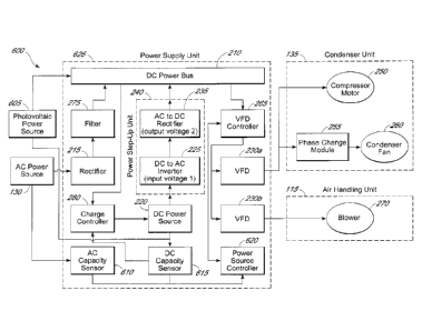
[0036] Fig. 6 is a schematic block diagram illustrating an embodiment
of an
HVAC/R power supply system 600 with a rechargeable DC power back-up, which
utilizes a
photovoltaic power source 605. Fig. 6 is the system of Fig. 2 augmented with a
photovoltaic
power source 605, additional sensors 610 and 615 and an additional controller
620.
100371 Photovoltaic power source 605 is an electric device that
converts solar
radiation such as ambient light to electrical energy. Photovoltaic power
generators are
typically one or more panels comprising photovoltaic cells that produce a
voltage when
-12-
CA 2765018 2017-11-09
exposed to solar radiation. Photovoltaic power sources may be portable (e.g.
attached to a
trailer) or may be permanently installed in the ground or permanently affixed
to a shelter or
enclosure. Photovoltaic power sources output DC power; however, in some
embodiments the
photovoltaic power source may be connected to an inverter, which converts the
DC output to
AC, or may have an integral inverter. Photovoltaic power sources that are
connected to an
inverter may output single phase or multi-phase AC power at a variety of
voltages and
wattages. Photovoltaic power sources may have power output (usually rated in
wattage) that
varies based on the size of the system (e.g. the number of panels) as well as
the ambient
conditions (e.g. direct versus indirect light). Embodiments of photovoltaic
power sources are
well known in the art. Photovoltaic power source 605 is electrically connected
to the DC
power bus 210. In alternative embodiments, the photovoltaic power source 605
may include
an integral inverter and be connected instead to rectifier 215 instead. In yet
other
embodiments, where, for example, the photovoltaic power source 605 has very
limited
capacity, the photovoltaic power source 605 may be directly connected to
charge controller
280 and only serve to provide charge to DC power source 220.
100381 AC capacity sensor 610 is electrically connected to the AC
power source
130. The AC capacity sensor may be either the active sensing type, which works
by sensing
the instant power available at the connection point, or of the passive type,
whereby a signal is
sent to the AC capacity sensor corresponding to the power output capacity.
Additionally,
other sensing methods, as are known in the art, may be used. Useful switching
and sensing
components and circuits are described in U.S. Patent No. 7,227,749.
The AC capacity sensor 610 is also electrically connected to a power source
controller 620, which is described in more detail below.
100391 DC capacity sensor 615 is electrically connected to the DC
power source
220 and to photovoltaic power source 605. The DC capacity sensor may be either
the active
sensing type, which works by sensing the instant capacity of the DC power
source as well as
the instant output of the photovoltaic power source 605, or of the passive
type, whereby the
DC power source 220 and photovoltaic power source 605 each sends a signal to
the DC
capacity sensor 615 corresponding to its power output capacity. With DC power
sources,
such as batteries, the capacity of the power source is generally based on the
instant voltage of
the power source. For example, as the measured voltage across the battery's
terminals
-13-
CA 2765018 2017-11-09
CA 02765018 2012-01-23
decreases, so too does the calculated DC power source capacity. However, other
sensing
methods, as are known in the art, may be used. Additionally, the DC capacity
sensor 615 is
electrically connected to the power source controller 620, which is described
in more detail
below.
[0040] The
power source controller 620 is electrically connected to one or more
power capacity sensors, such as AC capacity sensor 610 and DC capacity sensor
615. In this
embodiment, the power source controller 620 is also electrically connected to
the VFD
controller 265. The power source controller 620 receives power output capacity
data from the
sensors connected to it, as well as power load data from the VFD controller
and calculates a
power source distribution. In simple embodiments, the power source controller
620 might
instruct the VFD controller 265 to choose either the AC power source 130, the
photovoltaic
power source 605, or the DC power source 220 as a power source for operation
of the
HVAC/R components. In a preferred embodiment, the power source controller 620
senses
the load required from the VFD controller and instructs the VFD controller to
selectively
draw power from each power source in an optimal fashion. For example, if the
photovoltaic
power source 605 is sufficient to meet the instant needs of the HVAC/R
components, it
would be most efficient and economical to draw power from only that source.
However, if
the load exceeds the photovoltaic power source's 605 total output, the power
source
controller 620 could supplement the power with either the AC power source 130
or the DC
power source 220, so as to not overload the photovoltaic power source 605. For
example,
during periods of start-up of the HVAC/R components, power needs may
temporarily exceed
the total power output of the photovoltaic power source 605, or the instant
power capacity of
the same. In such a case, the power source controller 620 would direct the VFD
controller
265 to utilize stored capacity in the DC power source 220 or available
capacity from the AC
power source 130 to avoid overload of the photovoltaic power source 605 and
potential
I IVAC/R component damage. Likewise, the power source controller 620 may
instruct the
VFD controller 265 to reduce its power draw given the combined capacity of the
DC power
source 220 and photovoltaic power source 605 when AC power source 130 is
unavailable. In
preferred embodiments, the power source controller 620 can cause the VFD
controller to
draw power in any increment (e.g. 0% - 100%) from any available power source,
such as the
-14-
photovoltaic power source 605, the AC power source 130 and the DC power source
220.
Notably, in other embodiments, there may be additional power sources.
[0041] In other embodiments, the power source controller 620 may be
incorporated into the VFD controller 265. In such embodiments, the VFD
controller is
capable of receiving data from the AC capacity sensor 610 and the DC capacity
sensor 615
so that it may regulate the power drawn from each power source in accordance
with the load
required by the HVACJI1 system and other logic.
[0042] The power source controller 620 may comprise a microprocessor
or
computing system including software and hardware configured to accomplish the
aforesaid
operations. Examples of controller features and functions are described in
U.S. Patent No.
7,630,856 .
[0043] Fig. 7 is a flowchart showing exemplary logic' for a
controller, such as
power source controller 620 in Fig. 6. In the embodiment of Fig. 7, the power
source
controller is photovoltaic power biased; that is, the controller will prefer
to always draw from
a photovoltaic power source, such as the photovoltaic power source 605 of Fig.
6, rather than
other power sources. This strategy is not required, but may be preferable
where it is desirable
to keep the DC power source at max capacity as often as possible and to
minimize draw from
a traditional AC power source. Further, it may be desirable to reduce the
cycling (i.e. charge-
discharge-charge) of the DC power source to extend the lifetime of the DC
power source.
[0044] At state 705 the power source controller 620 receives capacity
data from
an AC capacity sensor, such as sensor 610 in Fig. 6. Next, at state 710 the
power source
controller 620 receives capacity data from a DC capacity sensor, such as
sensor 615 in Fig. 6.
Then at state 715, the power source controller receives load data from the VFD
controller,
such as controller 265 in Fig. 6.
[0045] At decision state 720, the power source controller 620
compares the
current load to the available photovoltaic power capacity. If the load is less
than or equal to
the photovoltaic capacity, then at decision state 740 the power source
controller 620
determines whether the DC power source is being drawn from. If the DC power
source is
being drawn from, the power source controller 620 instructs the VFD to draw
power from the
photovoltaic power source only at state 750, since there is ample photovoltaic
capacity. Then
the power source controller 620 loops back into data gathering at step 705. If
no power is
-15-
CA 2765018 2017-11-09
CA 02765018 2012-01-23
being drawn from the DC power source, then the power source controller
determines whether
the AC power source is being drawn from at decision state 745. If the AC power
source is
being drawn from, the power source controller 620 instructs the VFDs to draw
power from
the photovoltaic power source only at state 750. If no power is being drawn
from the AC
power source, then the power source controller loops back into a data
gathering step at state
705.
100461 If, at decision state 720, the load is greater than the
photovoltaic power
source alone can provide, the power source controller then determines whether
the load is
greater than the combined capacity of the photovoltaic power source and the AC
power
source at decision state 725.
100471 If, at decision state 725, the combined power capacity of the
photovoltaic
power source and AC power source are adequate to cover the load, the power
source
controller 620 instructs the VFD controller to draw the supplemental power
from the AC
power source at state 755. Then the power source controller 620 loops back
into data
gathering at step 705. If, on the other hand, the load is greater than the
combined power
capacity of the photovoltaic power source and AC power sources, then the power
source
controller 620 determines if the load is greater than the combined power
capacity of the
photovoltaic power source, AC power source and DC power source at decision
state 730.
[0048] If, at decision state 730, the load is less than or equal to the
combined
power capacity of the photovoltaic power source, AC power source and DC power
source,
the power source controller 620 instructs the VFD controller to draw
supplemental power
from the DC power source at state 760. Then the power source controller loops
back into a
data gathering step at state 705. If, on the other hand, the load is greater
than the combined
power capacity of the photovoltaic power source, AC power source and DC power
source,
the power source controller instructs the VFD controller to reduce power draw
at state 735.
For example, at state 735, the power source controller could instruct the VFD
power
controller to lower the speed of all motors attached to the VFDs to reduce
overall power
draw. Then the power source controller loops back into a data gathering step
at state 705.
Fig. 7 is merely one exemplary embodiment of programming logic that may be
used with the
power source controller 620.
-16-
CA 02765018 2012-01-23
100491 While
the above detailed description has shown, described, and pointed
out novel features as applied to various embodiments, it will be understood
that various
omissions, substitutions, and changes in the form and details of the devices
and processes
illustrated may be made by those skilled in the art without departing from the
spirit of the
invention. As will be recognized, the present invention may be embodied within
a form that
does not provide all of the features and benefits set forth herein, as some
features may be
used or practiced separately from others.
-17-