Note: Descriptions are shown in the official language in which they were submitted.
CA 02765040 2013-09-16
COMPRESSOR FREEZE UP PREVENTION IN COLD
WEATHER
BACKGROUND
[0002] The invention relates generally to a compressor and, more
specifically, a
freeze prevention system and method. A compressor may be used in a variety of
application and environmental conditions. Unfortunately, the compressor may be
subject to ice formation and/or debris buildup, which can reduce the
performance of
the compressor. For example, ice may form within a valve of the compressor.
BRIEF DESCRIPTION
[0003] Certain aspects commensurate in scope with the originally claimed
invention are set forth below. It should be understood that these aspects are
presented
merely to provide the reader with a brief summary of certain forms the
invention
might take and that these aspects are not intended to limit the scope of the
invention.
Indeed, the invention may encompass a variety of aspects that may not be set
forth
below.
[0004] The present embodiments provide a control system and method that is
able
to automatically cycle one or more compressor valves, for example to prevent
freeze
up. For example, in one embodiment, a system includes a compressor having a
compression device configured to increase a pressure of a gas, a valve
configured to
control flow of the gas from the compression device, and a controller
configured to
cycle the valve to reduce buildup of contaminants in the compressor.
[0005] In another embodiment, a system is provided having a compressor. The
compressor includes a compression device configured to increase a pressure of
a gas,
1
CA 02765040 2014-02-18
a valve configured to control flow of the gas from the compression device, and
a
controller configured to cycle the valve at a plurality of set points after
startup of the
compressor to reduce buildup of ice in the compressor.
10006] The present
embodiments further provide a method including cycling a
valve of a compressor at a plurality of set points after startup of the
compressor to
reduce buildup of ice in the compressor.
[0006a] A preferred aspect of the present invention is a system having a
compressor, the compressor comprising: a compression device configured to
increase
a pressure of a gas; an outlet flow path configured to flow the gas out of the
compressor; a valve disposed along the outlet flow path and configured to
control
flow of the gas from the compression device; and a controller comprising a
tangible,
non-transitory storage medium storing one or more algorithms executable by a
processor to cause the controller to cycle the valve a plurality of times when
an input
is received that a set point has been reached.
[0006b] A further aspect of the present invention is a system having a
compressor,
the compressor comprising: a compression device configured to increase a
pressure of
a gas; a valve configured to control flow of the gas from the compression
device; and
a controller comprising a tangible, non-transitory storage medium storing one
or more
algorithms executable by a processor to cause the controller to cycle the
valve
between an open position and a closed position a plurality of times at every
instance
of each of a plurality of set points after startup of the compressor to reduce
buildup of
ice in the compressor.
[0006c] Still a further aspect of the invention is a method of reducing
buildup of ice
in a compressor, the method comprising: receiving feedback that one set point
of a
plurality of set points has been reached after startup of the compressor; and
cycling a
valve of a compressor a plurality of times to reduce buildup of ice in the
compressor.
2
CA 02765040 2014-02-18
DRAWINGS
[0007] These and other features, aspects, and advantages of the present
invention
will become better understood when the following detailed description is read
with
reference to the accompanying drawings in which like characters represent like
parts
throughout the drawings, wherein:
[0008] FIG. 1 is a diagrammatical overview of a work vehicle having a
service
pack with a compressor configured to perform valve cycling to prevent and/or
breakup ice or debris buildup in accordance with aspects of the present
embodiments
is installed;
[0009] FIG. 2 is diagrammatical representation of a compression and control
system that is configured to prevent and/or breakup ice or debris buildup in
the
compressor in accordance with present embodiments;
[0010] FIG. 3 is a diagrammatical representation of an embodiment of the
compressor, wherein the compressor performs cycling of a main control valve to
prevent and/or break up ice or debris build up in the compressor; and
[0011] FIG. 4 is a process flow diagram of an embodiment of a method for
performing cycling of a main control valve of a compressor to prevent and/or
breakup
ice or debris buildup.
DETAILED DESCRIPTION
[0012] As discussed below, embodiments of the present technique provide a
uniquely effective solution to pressure management in compressors. Thus, the
2a
CA 02765040 2013-09-16
disclosed embodiments relate or deal with any application where a compressor
is
powered, such as by a CI or SI engine, and the load or combination of loads
are
intermittently applied to the engine. In certain embodiments, the disclosed
pressure
management techniques may be used with various service packs to prevent an
over
pressuring condition of a compressor. For example, the disclosed embodiments
may
be used in combination with any and all of the embodiments set forth in U.S
Publication No. 2008-0264922, published October 30, 2008, and entitled "ENGINE-
DRIVEN AIR COMPRESSOR/GENERATOR LOAD PRIORITY CONTROL
SYSTEM AND METHOD," which may be referred to for further details. By further
example, the disclosed embodiments may be used in combination with any and all
of
the embodiments set forth in U.S Publication No. 2008-0122195, published May
29,
2008, and entitled "AUXILIARY SERVICE PACK FOR A WORK VEHICLE,"
which may be referred to for further details.
[0013] As discussed below, the present embodiments utilize pressure sensing
from
the compressor, thereby providing feedback to a controller and/or user to
prevent
freeze-up and/or debris buildup in the compressor. For example, during cold
weather,
such as on a snowy or cold and rainy day, there may be an accumulation of ice
internal to the compressor. A controller configured according to the present
embodiments may cycle a solenoid-activated valve between an open and a closed
position to loosen the ice that has accumulated inside the compressor.
Additionally, it
should be noted that if significant buildup is present, the cycling may not
result in
large movement of the valve (i.e., the valve may not be able to reach the
fully open or
fully closed positions). The cycling may be performed at a number of different
set
points, such as pressures, as described below. As an example, the controller
may
cycle the valve at pressures of 75, 85, and at 150 psi, which may also
correspond to
the amount of time that the compressor has been in operation since being
turned on.
It should be noted that the pressures at which the valve is cycled may be
determined
based upon manufacturing specifications, or may be user-defined.
[0014] As noted above, the present embodiments of a control system that is
configured to perform valve cycling in a compressor is applicable to a variety
of
implementations, including work vehicles. FIG. 1 illustrates a work vehicle 10
including a main vehicle engine 12 coupled to a service pack module 14. The
service
3
CA 02765040 2011-12-08
WO 2010/144596
PCT/US2010/037999
pack 14 includes equipment that is capable of providing resources such as
electrical
power, compressed air, and hydraulic power. The equipment may be powered with
or
without assistance from the main vehicle engine 12. For example, a service
engine 16
may power the service pack 14. Thus, in some embodiments, the operator can
shut
off the main vehicle engine to reduce noise, conserve fuel, and increase the
life of the
main vehicle engine 12, as the service engine 16 is typically smaller and
thus,
consumes less fuel. As an example, the service pack engine 16 may include a
spark
ignition engine (e.g., gasoline fueled internal combustion engine) or a
compression
ignition engine (e.g., a diesel fueled engine), for example, an engine with 1-
4
cylinders with approximately 10-80 horsepower.
[0015] The service pack 14 may have a variety of resources, such as
electrical
power, compressed air, hydraulic power, and so forth. In the illustrated
embodiment,
the service pack 14 includes a pump 18. In particular, the pump 18 may include
a
hydraulic pump, a water pump, a waste pump, a chemical pump, or any other
fluid
pump. According to present embodiments, the service pack 14 includes an air
compressor 20 as well as a generator 22. The air compressor 20 and the
generator 22
may be driven directly, or may be belt, gear, or chain driven, by the service
engine 16
or one or more motors to which the service engine 16 and/or the pump 18 is
coupled
(e.g., a hydraulic motor). The generator 22 may include a three-phase
brushless type,
capable of producing power for a wide range of applications. However, other
generators may be employed, including single phase generators and generators
capable of producing multiple power outputs. The air compressor 20 may be of
any
suitable type, although a rotary screw air compressor is presently
contemplated due to
its superior output to size ratio. Other suitable air compressors might
include
reciprocating compressors, typically based upon one or more reciprocating
pistons. It
should be noted that the air compressor 20 contains one or more solenoid
valves, such
as a main control valve, that may be cycled at varying pressures to prevent or
breakup
ice or debris buildup.
[0016] The service pack 14 includes conduits, wiring, tubing, and so forth
for
conveying the services/resources (e.g., electrical power, compressed air, and
fluid/hydraulic power) generated to an access panel 24. The access panel 24
may be
located on any portion of the vehicle 10, or on multiple locations in the
vehicle, and
4
CA 02765040 2011-12-08
WO 2010/144596
PCT/US2010/037999
may be covered by doors or other protective structures. In one embodiment, all
of the
services may be routed to a single/common access panel 24. The access panel 24
may
include various control inputs, indicators, displays, electrical outputs,
pneumatic
outputs, and so forth. In an embodiment, a user input may include a knob or
button
configured for a mode of operation, an output level or type, etc. According to
the
embodiments described herein, at least one controller is present in or
operatively
coupled to the access panel 24. The controller is able to cycle the main
control valve
of the air compressor 20 to prevent the compressor 20 from freezing up due to
the
presence of contaminants, such as ice, particulate matter, etc. In cycling the
control
valve, the controller may substantially reduce or eliminate possible
compressor freeze
up situations. The controller may control all or a part of the service pack
14, which,
as noted above, supplies electrical power, compressed air, and fluid power
(e.g.,
hydraulic power) to a range of applications designated generally by arrows 26.
[0017] As depicted, air tool 28, torch 30, and light 32 are applications
connected to
the access panel 24 and, thus, the resources/services provided by the service
pack 14.
The various tools may connect with the access panel 24 via electrical cables,
gas (e.g.,
air) conduits, fluid (e.g., hydraulic) lines, and so forth. The air tool 28
may include a
pneumatically driven wrench, drill, spray gun, or other types of air-based
tools that
receive compressed air from the access panel 24 and compressor 20 via a supply
conduit (e.g., a flexible rubber hose). The torch 30 may utilize electrical
power and
compressed gas (e.g., air or inert shielding gas) depending on the particular
type and
configuration of the torch 30. For example, the torch 30 may include a welding
torch,
a cutting torch, a ground cable, and so forth. More specifically, the welding
torch 30
may include a TIG (tungsten inert gas) torch or a MIG (metal inert gas) gun.
The
cutting torch 30 may include a plasma cutting torch and/or an induction
heating
circuit. Moreover, a welding wire feeder may receive electrical power from the
access panel 24.
[0018] The fluid system of the service pack 14, such as the pump 18,
hydraulically
powers a vehicle stabilizer 34. The vehicle stabilizer 34 operates, for
example, to
stabilize the work vehicle 10 at a work site when heavy equipment is used.
Such
equipment may include a hydraulically powered crane 36 that may be rotated,
raised
and lowered, and extended (as indicated by arrows 38, 40 and 42,
respectively).
CA 02765040 2011-12-08
WO 2010/144596
PCT/US2010/037999
Again, the service pack 14 may provide the desired resources/services to run
various
tools and equipment without requiring operation of the main vehicle engine 12.
[0019] The vehicle 10 and/or the service pack 14 may include a variety of
protective circuits for the electrical power, e.g., fuses, circuit breakers,
and so forth, as
well as valving for the hydraulic and air service. For the supply of
electrical power,
certain types of power may be conditioned (e.g., smoothed, filtered, etc.),
and 12 volt
power output may be provided by rectification, filtering and regulating of AC
output.
Valving for fluid (e.g., hydraulic) power output may include by way example,
pressure relief valves, check valves, shut-off valves, as well as directional
control
valving. Moreover, the air compressor 26 may draw air from the environment
through an air filter and the pump 16 may draw fluid from and return fluid to
a fluid
reservoir.
[0020] Depending upon the system components selected and the placement of
the
service pack 14, reservoirs may be provided for storing fluid (e.g., hydraulic
fluid)
and pressurized air as noted above. However, the fluid reservoir may be placed
at
various locations or even integrated into the service pack 14. Likewise,
depending
upon the air compressor selected, no reservoir may be used for compressed air.
Specifically, if the air compressor 20 includes a non-reciprocating or rotary
type
compressor, then the system may be tankless with regard to the compressed air.
In
one embodiment, as noted above, the air compressor 20 may contain one or more
valves (e.g., a main control valve) that are subject to freeze-up due to ice
formation in
cold conditions and/or debris buildup. In embodiments where ice buildup (or a
similar contaminant) freezes the main control valve, the pressure within the
air
compressor 20 may cause a pressure relief valve to open, may cause the air
compressor 20 to shut down, or, in some situations, may cause the service pack
14 to
shut down altogether. As such, the present embodiments provide for the main
control
valve of the compressor 20 to be cycled to loosen, dislodge, or breakup ice
and/or
other contaminants.
[0021] In use, the service pack 14 provides various resources/services
(e.g.,
electrical power, compressed air, fluid/hydraulic power, etc.) for the on-site
applications completely independent of vehicle engine 12. For example, the
service
pack engine 16 generally may not be powered during transit of the vehicle from
one
6
CA 02765040 2011-12-08
WO 2010/144596
PCT/US2010/037999
service location to another, or from a service garage or facility to a service
site. Once
located at the service site, the vehicle 10 may be parked at a convenient
location, and
the main vehicle engine 12 may be shut down. The service pack engine 16 may
then
be powered to provide auxiliary service from one or more of the service
systems
described above. Where desired, clutches, gears, or other mechanical
engagement
devices may be provided for engagement and disengagement of one or more of the
generator 22, the pump 18, and the air compressor 20.
[0022] FIG. 2 is a block schematic illustrating an embodiment of a control
and
monitoring system 50 wherein pressure, flow, or other operation parameters of
the air
compressor 20 are controlled or regulated directly on the control panel 24. In
the
illustrated embodiment, the air compressor 20 is drivingly coupled to the
engine 12
via a belt and pulley system including stub shaft 52, a pulley 54, a drive
belt 56, a
compressor pulley 58, and the compressor drive shaft 60. In the illustrated
embodiment, the engine 12 rotates the stub shaft 52 to transmit rotation and
torque via
the pulleys 54 and 58 and drive belt 56 to the compressor drive shaft 60
coupled to the
air compressor 20. Accordingly, the mechanical energy generated by the engine
12
operates the air compressor 20. Additionally, a clutch 62 is provided. The
clutch 62
is generally configured to enable engagement and disengagement of the
compressor
20 with the compressor pulley 58 and, in turn, the engine 12. For example, the
clutch
62 may include an electromagnetic clutch, a wet clutch, or another suitable
clutch
configuration.
[0023] The system 50 includes control circuitry 64 having a processor 66
and
memory 68, wherein the system 50 may be controlled or monitored by an operator
through the control panel 24. In this embodiment, the control panel 24
includes a
regulator 70, a pressure gauge 72, and one or more user inputs 74, which may
be used
to monitor, regulate, or generally control various features of the air
compressor 20 as
discussed in further detail below. For example, the regulator 70 enables tool-
free
control of the air pressure of the air compressor 20, obviating the need for
special
tools to perform such tasks. The ability to control pressure via the regulator
70 also
substantially reduces or altogether eliminates the need for accessing internal
components of the system 10 or other more time consuming tasks to adjust such
operational parameters. Indeed, an operator may work in conjunction with the
control
7
CA 02765040 2011-12-08
WO 2010/144596
PCT/US2010/037999
circuitry 64 to perform cycling of one or more valves of the compressor 20, as
discussed below. As an example, the user may adjust the pressure within the
compressor 20 in a manner that provides finer control over pressurization
rates,
heating rates, and so forth, than would be available with normal operation of
the
compressor 20.
[0024] As an example, a user may desire to provide one or more sensors,
such as a
temperature sensor, in or around the compressor 20, as discussed below. The
sensor
may have respective monitoring and control circuitry, which the user may
interface
with the access panel 24 as the inputs 74. Generally, the inputs 74 may
include one or
more knobs, buttons, switches, keypads, or other devices configured to select
an input
or display function, as discussed further herein. The control panel 24 may
include one
or more display devices 76, such as an LCD display, to provide feedback to the
operator. It should be noted that the control panel 24 is not limited to the
components
described herein, and may include any number of components as desired or
required
for monitor or control of the system 50, such as multiple user inputs, display
devices,
gauges, etc.
[0025] The air compressor 20 includes an outlet connection 78 for
connection to
air-operated devices, such as plasma cutters, impact wrenches, drills, spray
guns, lifts,
or other pneumatic-driven tools, such as those described above with respect to
FIG. 1.
Additionally, an outlet pressure line 80 is connected to the regulator 70 and
the
pressure gauge 72. An inlet valve 82 is located at the inlet of the air
compressor 20.
A control pressure line 84 is connected from the inlet valve 82 to the
regulator 70 to
provide for control of the pressure generated by the air compressor 20. A main
control valve 86, such as a solenoid-driven valve, controls the amount of
compressed
(pressurized) gas that flows out of the compressor 20. In the present context,
the
regulator 70 may be manually and/or automatically adjusted to cycle the valve
86 at
varying pressures to dislodge contaminants (e.g., ice, dirt, clay, and the
like). For
example, in situations where the valve 86 experiences a larger than average
amount of
contaminant buildup, the electronic control 64 may provide for the valve 86 to
be
cycled at different pressures, such as at three different pressures (e.g.,
between
approximately 70 and 80 psi, 80 and 90 psi, and 120 and 160 psi). It should be
noted
that any number of cycles and pressures may be utilized to perform cycling,
such that
8
CA 02765040 2011-12-08
WO 2010/144596
PCT/US2010/037999
the number of cycles includes one or a plurality of cycles (e.g., 2, 3, 4, 5,
6, 7, 8, 9, 10
or more) and one or a plurality of pressures. Further, as the pressure at
which the
valve 86 is cycled increases, it should be noted that a greater amount of
force may be
applied to any contaminant buildup. In this way, a cycle at 150 psi applies
more force
than a cycle at 75 psi. Further, the amount of time at which the valve 82 is
cycled
may vary, such as between approximately 0.5 and 10 seconds (e.g.,
approximately
0.5, 1, 2, 3, 4, 5, 6, 7, 8, 9, or 10 seconds). Automatic and/or manual
control of the
valve 82 is described in further detail below.
[0026] In addition to cycling the valve 86 to prevent compressor freeze up,
the
compressor 20 may also provide a heating element 88 and a temperature sensor
90 for
heating an area of the compressor in response to measured temperatures. For
example, when appropriate, a user may activate a heating system at the access
panel
24 (such as via the inputs 74), or the control circuitry 64 may automatically
activate
the heating system based on temperature measurements performed by the
temperature
sensor 90. Such heating may be desirable when the compressor 20 is deployed in
cold
weather, such as in icy, rainy, and/or snowy conditions, when the possibility
that ice
has built up or will build up is likely. In another embodiment, cycling the
valve 86
may provide heat to reduce the buildup of ice, such that the heating element
88 may
be excluded.
[0027] The regulator 70 is configured to regulate the pressure within the
compressor 20 via the outlet pressure line 80 and the control pressure line
84. Thus,
as the electronic control 64 performs the actions described herein, an
operator can
visualize the current pressure provided by the compressor 20 via the pressure
gauge
72, and then adjust the pressure up or down via the regulator 70 if desired.
An
operator may desire to decrease the pressure generated by the compressor 20 to
enable
the generator 22 (FIG. 1) to draw more mechanical power from the engine 12 to
increase electrical power, for example, to increase the electrical power
supplied to a
plasma cutter. An operator may use the gauge 72 and the regulator 70 to ensure
the
pressure generated by the compressor 20 stays within the operating pressure
range of
the plasma cutter, while at the same time reducing the pressure to provide
more power
to the plasma cutter. Additionally, an operator may control air flow rate by
adjusting
the speed of the engine 12 using the control circuitry 64 described above. An
operator
9
CA 02765040 2011-12-08
WO 2010/144596
PCT/US2010/037999
may also control the speed of the engine 12 by adjusting the user inputs 74 on
the
control panel 24. Thus, by controlling both air pressure through the regulator
70 and
engine speed/air flow through the user inputs 74, an operator may select the
air
requirements suitable for a plasma cutter, air tool, or other device connected
to the
system 10 in addition to performing valve cycling.
[0028] Pressure gauge 72 may be any type of pressure gauge having a
measurement range suitable for the range of pressures generated by the air
compressor
20. The illustrated pressure gauge 72 includes an analog face having marks
corresponding to pressure values that may be any desired unit of measurement,
such
as PSI, atm, bar, Pascals, mmHg, etc. The face of the pressure gauge 72 may
include
designated regions showing the operating pressure ranges of different air-
operated
devices connected to the air compressor 20 as well as the designated pressures
for
performing valve cycling (e.g., at pressure set points). Indeed, in one
embodiment,
the gauge 72 may also provide a form of control, such that adjusting valve
cycling
pressure set points on the gauge 72 adjusts the pressures at which the valve
82 is
cycled. Additionally, the designated regions may show a maximum or critical
pressure beyond which the air compressor 20 may not be safely operated. The
system
50 also may include an automatic shutoff control to disengage the compressor
20
from the engine 12, or shutoff the engine 12, or release pressure from the
compressor
20, or a combination thereof, if a critical pressure is reached or exceeded as
indicated
on the gauge 72, for example due to contaminant buildup within the compressor
20.
[0029] As discussed above, the air compressor 20 has a range of operating
pressures depending on the size of the components of the compressor, such as
the
case, inlet and outlet valves and the rotary screw mechanism. The top end of
this
operating pressure range indicates a maximum or critical pressure that the
operating
pressure of the compressor 20 that may increase wear or cause damage to the
compressor 20 or other components of the system 10. For example, in one
embodiment, the compressor 20 may have a maximum or critical pressure of 200
PSI.
If the operating pressure of the air compressor 20 exceeds this pressure, for
example
due to a buildup of contaminants, then internal components of the air
compressor 20,
the housing of such internal components, or the air compressor 20 may be
damaged.
CA 02765040 2011-12-08
WO 2010/144596
PCT/US2010/037999
In addition, internal oil pressures may also reach a critically high level,
resulting in oil
blowback and damage to internal seals.
[0030] To prevent damage to the compressor 20 or any other part of the
service
pack 14 or vehicle 10, the illustrated air compressor 20 includes a valve 92
that is
configured to open if the pressure of the compressor 20 exceeds the maximum or
critical pressure. The valve 92 provides a relief point that opens to reduce
the
possibility of potential damage associated with exceeding the maximum or
critical
pressures. Instead of a critically high pressure causing blowback through the
compressor 20 or damaging internal components, the pressure will be relieved
through the opening of the valve 92. In some embodiments, the valve 92 may be
a
pop-off valve or similar release valve capable of relieving built-up pressure.
[0031] The control system 50 is configured to address the possibility that
the
maximum or critical pressure of the air compressor 20 is inadvertently
reached. The
control system 50 may provide an automatic shutoff function to shutoff the
compressor 20 before or if the maximum or critical pressure is reached. The
automatic shutoff function automatically disengages the clutch 62 coupling the
air
compressor 20 to the compressor pulley 58 and the stub shaft 52 of the engine
12,
thereby turning off the compressor 20 and allowing the pressure to decrease.
The
electronic control 64 may activate the automatic shutoff function, for example
upon
receiving a pressure signal 94, which may be indicative of shutdown, from the
pressure gauge 72. The pressure gauge 72 sends the shutdown signal to the
electronic
control 64 if the pressure gauge 72 detects a pressure near or at the maximum
or
critical pressure. For example, to ensure the valve 92 does not open, the
shutdown
signal may be configured to be sent when the pressure gauge 72 detects a
pressure
slightly below the maximum or critical pressure. Once the electronic control
64
receives the shutdown signal from the pressure gauge 72, the electronic
control 64
disengages the electronic clutch 62 and shuts down the air compressor 20.
Alternatively, the electronic control 64 may receive pressure values from a
pressure
sensor located elsewhere in the system and make the determination to shutdown
the
compressor 20 based on those values, instead of receiving a shutdown signal
from the
pressure gauge 72. Alternatively, the pressure level sensed by the gauge 72
may be
used to initiate an automatic shutdown of the engine 12, automatic release of
pressure
11
CA 02765040 2011-12-08
WO 2010/144596
PCT/US2010/037999
via the valve 92, or automatic adjustment of the inlet valve 82 or main
control valve
86, or a combination thereof, to reduce pressure in response to a critical
pressure. In
other embodiments, the automatic shutdown may be initiated by a pressure
switch
located elsewhere in the system.
[0032] As the air compressor 20 may undergo periods of little to no use, it
may be
useful for the operator to know how long the compressor has been turned off or
inactive. In knowing how long the compressor 20 has been inactive, in lieu of
the
electronic control 64, a user may manually activate a valve cycling routine to
dislodge
any possible buildup of ice or other contaminant. Advantageously, the control
system
50 provides for storage of the hours of operation and periods of inactivity of
the air
compressor 20. The memory 66 of the electronic control 64 may be configured to
store the duration of operation and/or inactivity of the compressor 20, a
predetermined
service and/or maintenance time interval, temperatures sensed within the
period of
inactivity, pressure fluctuations during the period of inactivity, and the
likelihood of
contaminant buildup as determined by the processor 68. The duration of
inactivity of
the compressor 20 may be determined from the engagement of the electronic
clutch
62 (or lack thereof). The electronic control 64 monitors the duration of the
engagement or lack thereof of the electronic clutch 62 and stores that value
as the
duration of operation/inactivity of the compressor 20. The duration may be
stored as
any unit of time, such as hours, minutes, etc, and the processor 68 may
include
functions for converting between different units of time. Predetermined
likelihoods of
ice or contaminant buildup, such as typical dew or freezing points, may be
stored in
the memory 66 during programming of the electronic control 64. The processor
68
may compare the stored duration of inactivity of and the temperatures and/or
pressure
fluctuations sensed within the compressor 20 to the typical conditions for ice
or
contaminant buildup and calculate the likelihood that a contaminant (e.g.,
ice) is
present within the compressor 20.
[0033] In automatic operation, based on the determination, the processor 68
may
execute one or more algorithms stored on the memory 66 that is capable of
performing the valve cycling tasks. The display device 76 may display the
stored
duration of inactivity of the compressor 20 and the predetermined likelihood
of
contaminant buildup. Additionally, the user's input (via input 74) of
preferred
12
CA 02765040 2011-12-08
WO 2010/144596
PCT/US2010/037999
conditions for automatic start of the valve cycling processes and/or the
preferred
conditions for notification for manual activation of the valve cycling
sequence may be
displayed on the display device 76. For example, in one embodiment, the user
input
74 may be a knob that provides selection of either the duration of inactivity
of the
compressor 20 or a percentage likelihood that contaminants such as ice are
present.
The control panel 24 also provides for resetting the user's inputs, through
operation of
the user input 74 and/or additional user inputs on the control panel 24. In
this manner,
the user may activate or deactivate automatic valve cycling processes where
desirable.
[0034] As noted above, the present embodiments are directed towards cycling
the
main control valve 86 of the compressor 20 to prevent freeze up due to ice or
debris
buildup. While the acts described above are provided in the context of a
service pack,
for example a pack able to provide hydraulic power, electrical power and the
like, it
should be noted that the approaches described herein may be applicable to a
variety of
compressors. For example, the valve cycling noted above provides system 50
that
includes an electronic control mechanism, which is the control circuitry 64
containing
the processor 68 and memory 66. However, as illustrated in FIG. 3, the valve
cycling
may be performed by a compressor that is not coupled to a controller, or a
controller
that utilizes switches rather than discrete components capable of performing
non-
switching tasks. For example, rather than having algorithms capable of
performing
valve cycling routines as a result of one or more analyses, the compressor 20
may
include a variety of switches and so forth that activate the valve 86 upon
reaching
respective set points.
[0035] The compressor 20 in FIG. 3 is part of a compression system 100
having
engine power 102 provided to the compressor 20 to generate a pressure output
104
(i.e., in the form of pressurized gas). The system 100 also includes a
pressure
transducer 106 that may be a pressure sensor which senses the pressure input
and
output to and from the compressor 20, the inner pressure within the compressor
20,
and so on. The pressure transducer 106 may be configured to generate a
mechanical
or electrical signal in response to the measured pressure, and provide the
signal to an
overpressure switch 108 and a mechanical overpressure valve 110. The
overpressure
switch 108 and the overpressure valve 110 may be configured to receive the
pressure
signal and, at a set point, such as at a certain pressure, may be configured
to open the
13
CA 02765040 2011-12-08
WO 2010/144596
PCT/US2010/037999
mechanical overpressure valve 110. For example, in operation, the overpressure
switch 108 may receive, on a substantially constant basis, the pressure signal
from the
pressure transducer 106. When the overpressure switch 108 receives a signal
indicative of a pressure higher than a set point value (for example a
manufacturer's or
a user's set point), the switch may cause the mechanical overpressure valve
110 to
open.
[0036] Unfortunately, many compressors utilize oil and other lubricating
agents
for their internal parts. At the high pressures which cause the mechanical
overpressure valve 110 to open, it is therefore likely that there may be at
least some
blowback that causes oil and other lubricating agents to be ejected from the
compressor 20. To prevent the mechanical overpressure valve 110 (and the
overpressure switch 108) from activating, the compressor 20 may cause the
valve 86
to cycle at pressures lower than the pressure at which the overpressure switch
108
activates. Alternatively, a switch or controller may be present that overrides
the
overpressure switch 108, which prevents the mechanical overpressure valve 110
from
opening. The valve cycling, as mentioned above, also causes any contaminant
buildup (e.g., ice or other debris) to be loosened to avoid compressor freeze
up.
According to the present approaches, the valve cycling includes actuating the
valve
between open and closed positions. As noted above, however, such cycling may
not
necessarily result in the valve reaching the fully-open and/or fully-closed
positions. A
single valve cycle may last anywhere between approximately 0.5 and 10 seconds,
or
any other suitable duration as noted above. As an example, the valve 86 may be
turned off for the between approximately 0.5 and 10 seconds, followed by the
valve
being turned on. The number of cycles may be determined by a user or
manufacturer,
and may include a single off-on cycle or a plurality of off-on cycles (e.g., 1
to 20, 1 to
10, or 1 to 5).
[0037] As an example of the valve cycling process, the compressor 20 may
cycle
the valve 86 at distinct set points, for example at one or a plurality of time
points after
the compressor 20 starts up. The time points may be, for example, between
approximately 5 seconds and 1 minute, 1 minute and 10 minutes, 10 minutes and
30
minutes, and so forth. The set time points may be the same or different time
delays
relative to one another, for example, every 30 seconds, every minute, every
hour, and
14
CA 02765040 2011-12-08
WO 2010/144596
PCT/US2010/037999
so on. Other set points may include temperatures and/or pressures. Indeed,
other set
points or sensed data is also contemplated, including acoustic, vibrational,
or any
other data that could be indicative of an impending compressor freeze up. In
embodiments where the temperature is measured (e.g., via a thermocouple or
similar
thermometer), the valve 86 may cycle at set temperatures, either as a result
of heat
generated by operation of the compressor 20 or a reduction of temperature in
cold
weather. It should also be noted that the valve 86 may produce a certain
amount of
heat during cycling, such that at least a portion of ice that may be present
in the
compressor 20 is melted. Additionally, a heater input 112 may be provided for
heating the compressor 20 and/or valve surroundings (e.g., to melt accumulated
ice).
[0038] According to the present embodiments, the valve 86 is cycled at set
pressure points. In cycling at set pressure points, the valve 86 may provide
an
increasing amount of force on any contaminant which may be mitigating proper
operation of the compressor 20 or the valve 86. As such, the pressure-
activated
cycling may be performed at a first pressure, at a second pressure, a third
pressure,
and so on, such that the set points include one or a plurality of pressure set
points
(e.g., 2 to 100). As an example, a first pressure set point may be between
approximately 50 and 80 PSI (e.g., 50, 60, 70, 75, or 80 PSI), a second
pressure set
point may be between approximately 80 and 100 PSI (e.g., 80, 85, 90, 95 or 100
PSI),
and a third pressure set point may be between approximately 100 and 180 PSI
(e.g.,
100, 110, 120, 130, 140, 150, 160, 170, or 180 PSI). Indeed, while the present
valve
cycling is performed at these pressures, both higher and lower pressures are
contemplated herein, such as lower than approximately 50 PSI and higher than
approximately 180 PSI.
[0039] In addition to the systems described above which are configured to
perform
valve cycling, the embodiments described herein also provide a method of
operating a
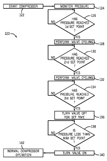
compressor after startup. More specifically, a method 120 is provided for
preventing
compressor freeze up or, alternatively, for mitigating the effect of
contaminant
accumulation on the operation of the compressor 20. Therefore, the method 120
begins with starting the compressor 20 (block 122), for example by a keyed
ignition, a
start button (for example, located on the compressor 20 or the access panel 24
of
FIGS. 1-2), or similar feature. The pressure is then monitored (block 124),
for
CA 02765040 2011-12-08
WO 2010/144596
PCT/US2010/037999
example, by a pressure transducer (i.e., sensor), that is configured to
provide a signal
indicative of the current pressure within the compressor 20 to a controller or
similar
feature. The compressor 20 (e.g., the processing component 68 of control
circuitry
64) may then determine whether the pressure in the compressor 20 has reached
the
first set point (block 126). In situations where the compressor 20 has not yet
reached
the first set point (e.g., first temperature, time, or pressure), the method
120 cycles
back to monitoring. In situations where the first set point has been reached,
the
method 120 progresses to performing valve cycling (block 128) as described
above.
[0040] After the initial valve cycling is performed (block 128), which may
include
one or a plurality of off-on cycles, the method 120 then progresses to another
determination as to whether the compressor 20 has reached the second set point
(block 130). In situations where the compressor 20 has not reached the second
set
point, the method 120 cycles back to monitoring. However, in situations where
the
compressor 20 has indeed reached the second set point, the compressor 20 may
then
perform a second set of valve cycling (block 132).
[0041] After the second set of valve cycling is performed (block 132),
which may
include one or a plurality of off-on cycles as noted above, the method 120
then
progresses to another determination as to whether the compressor 20 has
reached the
third set point (block 134). In situations where the compressor 20 has not
reached the
third set point, the method 120 cycles back to monitoring. However, in
situations
where the compressor 20 has indeed reached the third set point, the compressor
20
may then open the valve 86 for a designated time (e.g., between approximately
0.5
and 10 seconds) (block 136). After the designated time has elapsed, the method
120
then progresses to a determination as to whether the pressure within the
compressor
20 is less than a maximum set point (block 138). In situations where the
pressure is
greater than the maximum set point (e.g., not less than), the method 120
provides for
the compressor 20 to keep the valve 86 off for the set time again, followed by
making
the same determination until the pressure is below the maximum set point. In
this
way, the method 120 prevents the overpressure switch 108 and the mechanical
overpressure valve 110 of system 100 from activating while the valve cycling
routine
is in play. After a determination has been made that the pressure within the
16
CA 02765040 2013-09-16
compressor 20 is below the maximum set point, the valve 86 may be turned on
(block
140). Thereafter, the compressor 20 may carry out normal operation (block
142).
100421 While only
certain features of the invention have been illustrated and
described herein, many modifications and changes will occur to those skilled
in the
art. It is, therefore, to be understood that the scope of the claims should
not be limited
by the preferred embodiments set forth in the examples, but should be given
the
broadest interpretation consistent with the description as a whole.
17