Note: Descriptions are shown in the official language in which they were submitted.
CA 02765062 2011-12-09
WO 2011/000083 PCT/CA2010/000962
EMERGENCY VEHICLE NOTIFICATION SYSTEM
FIELD OF THE INVENTION
The present invention relates generally to emergency vehicle warning systems.
More particularly, the present invention relates to a system, method, and
various
components for use in warning traffic regarding the approach of an emergency
vehicle.
BACKGROUND OF THE INVENTION
With current trends in suburban development, infrastructure limitations
generally
result in increasing congestion along feeder routes due to the increasing
number of
vehicles requiring access to urban areas. Additionally, high density urban
housing
developments create further congestion and limit access and visibility while
driving. This
often leaves motorists with limited notice of potential hazards, and fewer
options for route
adjustment to avoid congested areas. For most road users this poses little
more than an
inconvenience, easily remedied by lowering their rate of speed, increasing
travel time and
keeping in tight control of their vehicle.
Emergency vehicles, however, must avoid congested routes or provide
appropriate
notification to traffic users to clear the desired route for passage of the
emergency vehicle.
The inherent urgency of emergency vehicle travel necessitates effective
notification to
other traffic to clear the route as quickly as possible. It has become
increasingly difficult to
timely notify and navigate congested traffic through urban and suburban areas.
It is also
generally desirable for emergency vehicles to be able to travel at speeds
greater than those
permitted for other vehicles. Emergency vehicles travelling at high speeds
through
congested areas pose a risk to all users of the roadway, as well as to
individuals seeking
emergency assistance.
Common methods of warning motorists of an approaching emergency vehicle
include visual and audible warning devices (lights and sirens of various
patterns). Most
provinces or states have laws requiring motorists to pull over when such
warning
mechanisms are near, allowing emergency vehicles the right of way while
reducing
opportunity for collision.
Warning lights and sirens, however, have limitations. While the majority of
drivers
are aware of appropriate action to take when an emergency vehicle is
approaching (for
1
CA 02765062 2011-12-09
WO 2011/000083 PCT/CA2010/000962
example, pulling over to the right side of the road), drivers are often
startled by lights and
sirens approaching from behind, and are also often confused as to the
direction of the
approaching emergency vehicle. Accordingly, there may be limited opportunity
for the
driver to manoeuver out of the path of the emergency vehicle. This causes
erratic motorist
response, and confusion for all parties. It is therefore common for emergency
vehicles to
be seen weaving in and out of such erratic/stalled traffic.
Thus, drivers of emergency vehicles typically must proceed more slowly than
desirable, increasing their response time.
U.S. Pat. No. 5,307,060 to Prevulsky, describes a vehicle to vehicle emergency
communication system. Emergency vehicles are equipped with transceivers for
communication with other emergency vehicles, and for sending alerts to non-
emergency
vehicles. Non-emergency vehicles are equipped with a vehicle alert receiver to
receive
permit notification of an approaching emergency vehicle and its type.
Similarly, U.S. Pat. No. 6,529,831 to Smith, describes an in-vehicle
notification
and navigation system to allow a driver to navigate away from the path of an
second
(presumably an emergency) vehicle.
Beinke, in U.S. Pat. No. 6,404,351, teaches a system for installation in
emergency
vehicles. The system not only notifies other vehicles of approaching emergency
vehicles,
but also has the ability to change traffic lights in a further effort to clear
the roadways for
emergency traffic. Non-emergency vehicles receive in-car alerts via an
installed
directional display and speaker.
U.S. Pat. No. 5,889,475, issued to Klosinski, describes alert transmissions
across
AM and FM frequencies to warn vehicles through existing radio devices.
In summary, lights and sirens currently serve the purpose of general
notification to
surrounding drivers of a nearby emergency vehicle, but emergency vehicle-based
lights
and sirens are limited in the quality of information provided to other
drivers. More specific
notification technologies (as discussed above) generally require installation
of specialized
equipment directly within emergency and non-emergency vehicles to enable an
alert
service. It would be desirable to provide suitable notification to drivers
regarding the
direction of approach of an emergency vehicle, without requiring installation
of specific
equipment within the non-emergency vehicles.
2
CA 02765062 2011-12-09
WO 2011/000083 PCT/CA2010/000962
SUMMARY OF THE INVENTION
It is an object of the present invention to obviate or mitigate at least one
disadvantage of previous emergency vehicle notification systems.
In a first aspect, there is provided a traffic notification system comprising:
a signal
generator for emitting an emergency signal; a series of signal receivers for
receiving
emergency signals; a series of traffic alert devices, each alert device
associated with at
least one of the signal receivers such that when the receiver detects an
emergency signal,
the corresponding traffic alert device is activated; and a series of signal
relays, each signal
relay associated with one of the signal receivers such that when the receiver
detects an
emergency signal, the signal relay sends a corresponding emergency signal in
the direction
of another one of the signal receivers, thereby propagating the emergency
signal.
In an embodiment, the signal generator is a transmitter on an emergency
vehicle.
In a further embodiment, the series of signal receivers, alert devices, and
signal
relays are arranged along a roadway. The system may further comprise a series
of alert
units, each alert unit for containing one of the signal receivers, one of the
alert devices,
and one of the signal relays.
In an embodiment, the receiver reduces the intensity of the signal prior to
the
signal relay sending the corresponding emergency signal, such that each
successive signal
relay propagates an emergency signal of successively reduced intensity.
In accordance with a second aspect, there is provided a method for alerting
traffic
of an approaching emergency vehicle, the method comprising the steps of.
emitting a first
emergency signal from an emergency vehicle; detecting the signal with a first
receiver at a
first location along a roadway; activating an alert device at the first
location to alert nearby
traffic of the approaching emergency vehicle; and initiating a relay signal at
the first
location to propagate the first emergency signal to another receiver at a
second location
along the roadway.
In a third aspect, there is provided an alert unit for mounting along a
roadway, the
alert unit comprising: a receiver for detecting an emergency signal; an alert
device for
displaying an emergency alert in response to emergency signal detection by the
receiver;
and a relay signal generator for activation by the receiver upon detection of
an emergency
signal, the relay signal generator for propagating the emergency signal to
another alert unit
along the roadway.
3
CA 02765062 2011-12-09
WO 2011/000083 PCT/CA2010/000962
In a fourth aspect, a method is provided for displaying an emergency alert
along a
roadway, the method comprising the steps of-
- providing a plurality of alert units, each comprising: a receiver for
detecting an
emergency signal, an alert device for displaying an emergency alert in
response to
emergency signal detection by the receiver; and a relay signal generator for
activation by the receiver upon detection of an emergency signal, the relay
signal
generator for propagating a relay signal from the alert unit;
- placing the alert units in series along a roadway such that the receiver of
each
successive alert unit is within detection distance of the preceding alert unit
relay
signal, when activated; and
- emitting an emergency signal in proximity to one of the alert units so as to
initiate
propagation of an emergency signal and alert along the roadway.
In a fifth embodiment, a method is provided for alerting traffic of an
approaching
emergency vehicle by activating a series of flashing lights along a roadway,
in the
direction of travel of the emergency vehicle.
Other aspects and features of the present invention will become apparent to
those
ordinarily skilled in the art upon review of the following description of
specific
embodiments of the invention in conjunction with the accompanying figures.
4
CA 02765062 2011-12-09
WO 2011/000083 PCT/CA2010/000962
BRIEF DESCRIPTION OF THE DRAWINGS
Embodiments of the present invention will now be described, by way of example
only, with reference to the attached Figures, wherein:
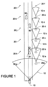
Fig. I is a schematic drawing showing operation of an alert system along a
roadway; and
Fig. 2 is a schematic drawing of an alert unit.
DETAILED DESCRIPTION
Generally, the present invention provides an emergency vehicle alert system.
A system and method are described for notifying appropriate vehicles of the
existence and direction of travel of an approaching emergency vehicle (e.g.
police, fire or
ambulance). Accordingly, drivers are aware that the emergency vehicle is
approaching
from behind, and can take action to clear the roadway, facilitating faster
emergency
response times and reducing confusion and potential for accidents.
With respect to Figure 1, an emergency vehicle 10 is equipped with a
transmitter
11, that emits a pulsing signal swath 12 in the direction of travel. Alert
units 20 are present
along each side of the roadway, and each contains a receiver 21 and alert
light 22, both
facing oncoming traffic, and a relay signal 23, directed towards the next
alert unit 20 along
the roadway. Accordingly, an emergency vehicle 10 travelling along the roadway
will
emit a signal swath 12 that is detected by the receiver 21 of any alert units
within range,
activating the alert light 22 and relay signal 23. Thus, the alert light 22
will flash and be
visible by drivers travelling ahead of the emergency vehicle. The alert unit
20 will also
propagate the emergency signal to the next alert unit along the roadway by
flashing relay
signal 23.
The system can easily be deployed within a municipality, without need for
individual vehicle owners to install any device in their own vehicles. The
system makes
use of existing infrastructure (for example lampposts, guardrails, etc.) as
mounting points
for the alert units 20, and transmitters can be installed in emergency
vehicles as desired.
Once installed, the alerting system is functional for all drivers collectively
and
immediately.
CA 02765062 2011-12-09
WO 2011/000083 PCT/CA2010/000962
Thus, a method for notifying drivers of emergency vehicles is available by
visual
queue of pulsing light, travelling directly in front of a driver. Drivers see
a pulse of light
along the roadway, travelling down the road ahead of their vehicle. As the
light pulse will
travel faster than traffic flow, drivers will see a repeating pulse of light
travelling in a
forward direction, indicating that an emergency vehicle is approaching from
the rear. The
driver therefore has time to respond, knowing that soon an emergency vehicle
will be
within visual / audible range.
A series of programmed microcontrollers work as a system to effectively
produce a
network of visible travelling light pulses ahead of the emergency vehicle,
customized for
distance and speed by road conditions. Once the alert units 20 are in place
along a
thoroughfare, they form an independent safety network that can be extended,
and/or
modified to fit changing traffic conditions. The components of the alert units
20 (receiver
21, alert light 22, and relay signal 23) may instead be provided as separate
devices and
mounted along the roadway as desired.
Depending on speed of traffic and notification requirements, each mounted unit
is
programmed for distance and intensity of the pulsating light travel. Range of
pulsating
light travel maybe set to multiple miles/kilometers ahead of the triggering
emergency
vehicle depending on traffic needs. The result provides a clear path for
emergency
vehicles by giving drivers time to react prior to the actual presence of the
emergency
vehicle.
Transmitter
The transmitter 11 is mounted to an emergency vehicle. Communication between
the transmitter and alert units may be by any means suitable for signal
propagation. A
signal of graded, measurable intensity will allow the system to fade the
signal as it is
propagated from the origin, if this is desirable for the specific application.
A directional
signal will allow the signal to be aimed along a particular side of the
roadway, or
otherwise oriented to receivers of interest.
With reference to Figure 1, an infrared signal is pulsed to create a 45-60
degree
swath ahead of the emergency vehicle. The angle of this signal allows
detection by alert
units along the right side of the road (i.e. in the direction of travel of the
emergency
6
CA 02765062 2011-12-09
WO 2011/000083 PCT/CA2010/000962
vehicle), as the receivers of these alert units are facing oncoming traffic,
but does not
activate alert units on other streets or on the opposite side of the roadway
due to
orientation of the receivers (see below).
The strength and timing of pulsing may be preset to a general setting, or may
be
controlled from within the emergency vehicle (or remotely) based on the
general traffic
patterns and road conditions present, as well as on the location of alert
units 20.
Alert Units
Multiple receivers, relay signals, and lights are placed along the roadway.
Each of
these components may be contained within an alert unit 20, as shown in Figure
2.
Typically, the units would be mounted to light standards, telephone poles,
guardrails, the
road surface itself, or any other suitable structure along the roadway that is
visible to
traffic.
Generally, the receiver is mounted and oriented to face oncoming traffic. By
facing traffic, the receiver can detect the pulsing signal swath 12 of
oncoming emergency
vehicles, or of an adjacent relay signal, for example from a nearby alert unit
20. However,
the receiver cannot detect signals from vehicles travelling in the opposite
direction, or on
nearby streets. In this manner, signals are only propagated in the direction
of travel of the
initiating emergency vehicle.
The receiver is in communication with an associated alert light 22 and relay
signal
23, activating both when an emergency signal is detected. The receiver may be
deactivated
for a set period of time after a signal detection to ensure proper timing of
signal
propagation along the roadway.
The alert light is similarly placed alongside the roadway and facing oncoming
traffic. Upon activation by communication from the receiver, the alert light
flashes, and is
visible to oncoming traffic. With appropriate signal propagation, the alert
lights will
generate a travelling light pulse in the direction of emergency vehicle
traffic that will be
easily visible and recognizable to other drivers. The alert lights may take
multiple forms
such as colored LED lights, strobe light, patterned light flashes, or any
other means of
conveying information effectively to motorists.
7
CA 02765062 2011-12-09
WO 2011/000083 PCT/CA2010/000962
The relay signal is oriented in opposite direction to the alert light such
that it faces
the receiver of the next alert unit. In this manner, the alert lights along
the roadway are
flashed in succession, creating a self-propagating signal along the roadway as
to the
direction of approach of the emergency vehicles.
Termination of Propagation
In order to prevent endless propagation of the signal along the roadway, which
may be unnecessary and counterproductive if the emergency vehicle stops of
turns off the
current roadway, the propagating signal may be measured and reduced in
intensity at each
relay to limit the distance of propagation.
The receiver may include an intensity meter that measures the intensity of the
signal received from the previous alert unit. The alert unit may then reduce
the intensity of
the signal relayed to the next alert unit. Accordingly, this would ensure that
over a given
number of relays, the signal would diminish and then eventually fail to
propagate after a
given distance from the original signal.
The intensity or count of the signal may be detected by appropriate
programming
of the alert unit microprocessor. The detected signal may then be reduced by
an
appropriate amount for relay to the next alert unit, thereby reducing the
intensity of the
signal as it is propagated. The amount of reduction in signal strength will be
set to allow
propagation to an appropriate distance from the originating signal, which will
depend on
various factors including the distance between the alert units, the average
speed of traffic
along the roadway, typical visibility, configuration of the roadway and cross
streets, etc.
Method
With reference to Figure 1, upon approach of an emergency vehicle 10 along a
roadway, the emergency vehicle would typically be flashing lights and sounding
a siren, in
proximity to vehicles 90, 91, 92. While vehicle 91 would be aware of the
location of the
emergency vehicle using rear view and/or side view mirrors, vehicle 90 may not
be able to
see the emergency vehicle 10, but will hear the siren. Generally, drivers that
detect an
audible siren but are not able to determine the location or direction of the
emergency
vehicle will slow down and look in all directions, causing traffic confusion.
8
CA 02765062 2011-12-09
WO 2011/000083 PCT/CA2010/000962
In accordance with the system shown in Figure 1, the emergency vehicle emits a
pulsing signal swath 12 from emitter 11. The pulsing swath only reaches a
certain distance
from the emergency vehicle 10, and therefore may only be detectable by alert
unit 20a.
Alert unit 20g cannot detect the pulsing signal swath 12 because the receiver
in alert unit
20g is facing the opposite direction. Accordingly, none of alert units 20b-201
will detect
the emergency vehicle signal swath 12 at this point in time.
Thus, the receiver on alert unit 20a detects the emergency vehicle emission,
flashes
light on alert unit 20a, which is visible only to the emergency vehicle 10.
The alert unit
20a sends a relay signal 12a to alert unit 20b. Unit 20b measures the
intensity of the signal,
flashes its light, and activates relay signal 12b within alert unit 20b at a
reduced intensity.
Adjacent unit 20c detects the reduced intensity signal, flashes its light, and
reduces the
intensity of the signal 12c relayed to alert unit 20d. Similarly, the signal
propagation and
light flashes continue until the signal is too weak to activate the following
alert unit (200.
Once the flashes of light are initiated, the driver of vehicle 90 is aware
that the
emergency vehicle is approaching from behind due to the visible light flashes
along the
roadway in his direction of travel, even though the driver cannot see the
emergency
vehicle due to the large vehicle 91 behind. Vehicle 91 need not look around
confused, but
can pull over knowing he must clear a path for the approaching emergency
vehicle.
Conversely, should the driver of vehicle 92 notice the light flashes, he can
be
assured that the approaching emergency vehicle is not approaching from behind,
as there
are no flashing lights in his direction of travel. The driver may observe the
flashing lights
on the opposite side of the road and determine whether any action is required.
Meanwhile, emergency vehicle has progressed along the roadway and is still
emitting the pulsing signal swath 12, which by now may be in directly within
range of
alert unit 20d. If alert unit 20d has recovered from its previous signal
relay, it can now
detect and act upon the signal from the emergency vehicle 10. Accordingly, the
propagating light flashes are repeated based on the direction of travel of the
emergency
vehicle.
The signal 11 may be disabled within the emergency vehicle 10 as desired, for
example when the road is clear or the destination has been reached.
9
CA 02765062 2011-12-09
WO 2011/000083 PCT/CA2010/000962
Other Embodiments
As an alternative to unidirectional signal propagation along one side of a
roadway,
some systems may employ bidirectional alert units (flashing a propagating
signal on either
side of the alert unit), which may be placed on either side of the roadway. In
such an
arrangement, the pulse of light travelling with the emergency vehicle may be
duplicated
along both sides of the roadway for additional visibility. Further, when a
bidirectional alert
signal is propagated, the signal would also be visible to oncoming traffic. As
a result,
oncoming traffic would see a travelling pulse of light approaching head-on,
and may slow
down or pull to the right to clear the middle of the roadway.
The pulsing signal swath may also be used to activate or disable other
systems, for
example traffic lights, custom in-car alert systems, and the like.
The system may also be used to warn drivers of other hazards such as wildlife,
pedestrians, etc. Various types of lights and displays may be used, for
example specific
colors indicating specific types of hazards, providing more specific
information to
motorists.
Other types of alerts may also be propagated by the alert unit, including
sirens,
radio signal interruptions or emergency messages, and the like.
Traffic control systems that rely on a centrally controlled system, network
communication, and other similarly connected systems have many potential
failure points
that rely on other technologies and modes of communication to operate. To
avoid
technological failure, the present system effectively builds a self reliant
communications
network, self propagating, and requires minimal user input to trigger, monitor
or function
effectively. Should contemporary traffic systems fail, this method would
additionally
serve as a backup for traffic emergency notification..
The above-described embodiments of the present invention are intended to be
examples only. Alterations, modifications and variations may be effected to
the particular
embodiments by those of skill in the art without departing from the scope of
the invention,
which is defined solely by the claims appended hereto.