Note: Descriptions are shown in the official language in which they were submitted.
CA 02765194 2015-07-21
349I3PCT
ON-LINE TIME DOMAIN REFLECTOMETER SYSTEM
BACKGROUND
Transmission cables are intended to operate safely and effectively over
lifespans
exceeding twenty years. However, because of anomalies in the transmission
cable due to
manufacturing defects, installation errors, localized imperfections, such as
insulation
breakdown, transmission cables often suffer premature breakdown. Should this
occur
during a critical period the repercussions in terms of financial losses and
customer
inconveniences can be quite severe. Therefore, with the ever-increasing number
of
transmission cables being utilized throughout the world, it is desirable that
anomalies
such as faults, discharges, cable damage, and splices of transmission cables
be located
without the necessity of physical tracing and inspection.
A Time Domain Reflectometer (TDR) is one apparatus that can be used to
analyze a cable for anomalies, and more specifically, to analyze the cable for
changes in
cable impedance in order to locate such anomalies. A typical TDR transmits a
pulse of
electrical energy onto a cable that includes two conductors separated by a
dielectric
material. When the pulse encounters a change in the impedance of the cable,
part of the
pulse's energy is reflected back toward the TDR. The amplitude and polarity of
this
reflection is proportional to the change in impedance. Such reflections are
usually
displayed in graphical form on the screen of a typical TDR whereby a
technician can
interpret the results and locate specific cable anomalies. In particular, the
time of
propagation of the pulse as well as the pulse shape can be used to identify
and locate the
anomaly along the transmission cable.
SUMMARY
This summary is provided to introduce a selection of concepts in a simplified
form that are further described below in the Detailed Description. This
summary is not
intended to identify key features of the claimed subject matter, nor is it
intended to be
used as an aid in determining the scope of the claimed subject matter.
In accordance with an embodiment of the present disclosure, an apparatus for
testing an electrical power system for anomalies is provided. The apparatus
includes a
CA 02765194 2011-12-12
WO 2011/005541 PCT/US2010/039540
computing device, a pulse generator that generates a pulse upon reception of a
command
signal from the computing device, and one or more capacitive test sensors
capable of
being capacitively coupled to an on-line power component of the electrical
power system.
At least one of the one or more capacitive test sensors receives the pulse
generated by the
pulse generator.
hi accordance with another embodiment of the present disclosure, a method of
testing a power system component for anomalies is provided. The method
comprises
capacitively coupling one or more test sensors to an on-line insulated power
cable,
generating a test pulse and transmitting the test pulse to at least one test
sensor of the one
or more test sensors, capacitively transmitting the test pulse from the at
least one test
sensor of the one or more test sensors onto the insulated power cable so that
the test pulse
travels along the insulated power cable, and capacitively receiving a
reflected pulse by
one test sensor of the one or more test sensors from the insulated power
cable. The
reflected pulse results from the test pulse interfacing with an anomaly along
the insulated
power cable.
In accordance with another embodiment of the present disclosure, a method of
testing a power system component for anomalies is provided. The method
comprises
connecting, in electrical communication, a pulse transmission line with a test
sensor
housed in a power cable termination elbow. The test sensor is housed in the
termination
elbow disposed with the termination elbow in such a manner as to be
capacitively
coupled to a power cable when the power cable is connected to the termination
elbow.
The method also includes generating a test pulse and transmitting the test
pulse to the test
sensor via the pulse transmission line, capacitively transmitting the test
pulse from the
test sensor onto the power cable so that the test pulse travels along the
power cable, and
capacitively receiving a reflected pulse by the test sensor from the power
cable. The
reflected pulse results from the test pulse interfacing with an anomaly along
the power
cable or an electronic component connected to the power cable.
DESCRIPTION OF THE DRAWINGS
The foregoing aspects and many of the attendant advantages of this disclosure
will
become more readily appreciated by reference to the following detailed
desctiption, when
taken in conjunction with the accompanying drawings, wherein:
-2-
CA 02765194 2011-12-12
WO 2011/005541 PCT/US2010/039540
FIGURE 1 is a schematic diagram of one embodiment of a TDR system formed in
accordance with aspects of the present disclosure;
FIGURE 2 is a block diagram of one embodiment of a computing device
employed by the TDR system of FIGURE I;
FIGURE 3 is a schematic diagram of another embodiment of a TDR system
formed in accordance with aspects of the present disclosure;
FIGURE 4 is a schematic diagram of another embodiment of a TDR system
formed in accordance with aspects of the present disclosure; and
FIGURE 5 is a schematic diagram of another embodiment of a TDR system
formed in accordance with aspects of the present disclosure; and
FIGURE 6 is a schematic diagram of another embodiment of a TDR system
formed in accordance with aspects of the present disclosure.
DETAILED DESCRIPTION
The detailed description set forth below in connection with the appended
drawings where like numerals reference like elements is intended as a
description of
various embodiments of the disclosed subject matter and is not intended to
represent the
only embodiments. Each embodiment described in this disclosure is provided
merely as
an example or illustration and should not be construed as prefened or
advantageous over
other embodiments. The illustrative examples provided herein are not intended
to be
exhaustive or to limit the disclosure to the precise forms disclosed.
Similarly, any steps
described herein may be interchangeable with other steps, or combinations of
steps, in
order to achieve the same or substantially similar result.
The following discussion proceeds with reference to examples of transmission
cable testing devices and methods. More particularly, embodiments of the
present
disclosure are directed to systems and methods that utilize Time Domain
Reflectometers
(TDRs) for testing, and potentially analyzing, insulated transmission cables,
such a
medium and low voltage power transmission cables, twisted cable pairs, coaxial
cable,
etc., power equipment, such as switchgears, transformers, electric motors,
etc., and the
like As will be explained in more detail below, some embodiments of the
present
disclosure provide a TDR system that tests an "on-line" or "energized" power
transmission cable by imposing a pulse of energy onto the power cable and
sensing the
CA 02765194 2011-12-12
WO 2011/005541 PCT/US2010/039540
potential reflection signals in a capacitive manner. In this way, technicians
do not need to
take the power cable off line nor do they need access to the power cable's
central
conductor.
As described herein, a Time Domain Reflectometer (TDR) transmits a pulse of
electrical energy onto a transmission cable, such as a power transmission
cable, that
includes two conductors, a power carrying conductor, and a neutral conductor,
separated
by a dielectric material. When the electrical pulse encounters an impedance
change along
the cable's length, part of the pulse's energy is reflected back toward the
TDR. By
measuring, for example, the amplitude and polarity of the reflected wave, the
proportionality of the impedance change can be determined. Additionally, by
measuring
the time of propagation of the pulse, the location of the impedance change can
also be
determined. Typical anomalies that will cause an impedance change include but
are not
limited to a change in the cable medium, splices, faults, neutral coffosion,
water damage
to the insulation and/or shield, and damage to the cable (e.g., broken
conductors, shorted
conductors, smashed cables, cuts, etc.)
In the following description, numerous specific details are set forth in order
to
provide a thorough understanding of exemplary embodiments of the present
disclosure.
It will be apparent to one skilled in the art, however, that many embodiments
of the
present disclosure may be practiced without some or all of the specific
details. In some
instances, well-known process steps have not been described in detail in order
not to
unnecessarily obscure various aspects of the present disclosure. Further, it
will be
appreciated that embodiments of the present disclosure may employ any
combination of
features described herein.
In accordance with several embodiments of the present disclosure, a number of
TDR systems are provided that improve the quality and accuracy of information
collected
when propagating a signal along a length of transmission cable in order to
pinpoint
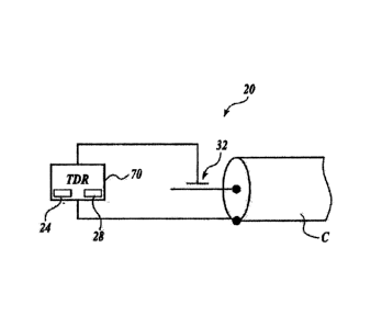
specific anomalies. Turning now to FIGURE I, there is shown a schematic
diagram of a
conventional transmission cable, such as a power cable C. As best shown in
FIGURE 1,
the power cable C is being tested by one embodiment of a TDR testing system,
generally
designated 20, formed in accordance with aspects of the present disclosure. In
some
embodiments, the TDR testing system may be utilized to test "energized" or "on-
line"
power cables C. As used herein, the term ''energized" or "on-line" means that
power is
presently being transmitted along the power cable C.
-4-
CA 02765194 2011-12-12
WO 2011/005541 PCT/US2010/039540
Still referring to FIGURE 1, the system 20 comprises a computing unit 2,4, a
pulse
generator 28, and a pulse transmit/receive sensor 32. In use, the pulse
generator 28, upon
instructions generated by the computing unit 24, generates a pulse of energy
that is
transmitted over the power cable C via the transmit/receive sensor 32. If the
pulse
encounters an anomaly as it propagates down the power cable C, a reflection
signal is
produced and transmitted back toward the transmit/receive sensor 32, where the
signal is
sensed by the transmit/receive sensor 32 and transmitted to the computing unit
24 to be
processed and displayed. In one embodiment, the signals received by the
computing
unit 24 may be analyzed to determine the location of the anomaly, the type of
the
anomaly, etc.
Referring to FIGURES 1 and 2, the components of the system 20 will now be
described in more detail. As briefly described above, the sensor 32 transmits
a pulse of
energy generated by the pulse generator 28, and then senses any reflections of
the
transmitted pulse. The sensor 32 may be a portable sensor for in-field data
acquisition
and/or testing or fixed in place at a termination location, such as a
termination elbow. In
one etnbodiment, the sensor 32 is a portable, capacitive probe, such as a U-
shaped
metallic (e.g., copper, etc.) probe. In use, the capacitive probe is
capacitively coupled to
the power cable C, at a position, for example, where the power cable is
terminated. In
embodiments that are testing underground power cables, the capacitive probe is
capacitively coupled to the power cable C at a location where the power cable
is exposed
(e.g., above ground, unearthed, etc.). Once coupled to the power cable, the
probe is
capable of imposing a pulse onto the power cable to be tested and sensing the
reflection
signals due to anomalies and transmitting these signals to the computing unit
24 for
displaying, processing, and/or storage, etc.
Referring now to FIGURE 2, there is shown a block diagram of one embodiment
of the computing unit 24 suitable for use with the system 20. The computing
unit 24 comprises a processor 44, a memory 48, a display 52, and an I/0 device
56
suitably interconnected via one or more buses 60. The memory 48 may include
read only
memory (ROM), random access memory (RAM), and storage memory. Examples of
ROM include a programmable ROM (PROM), an erasable programmable ROM
(EPROM), and an electrically erasable PROM (EEPROM). Examples of storage
memory
include flash memory, a hard disk drive, a magnetic disk drive for reading
from or
writing to a removable magnetic disk. and an optical disk drive for reading
from or
-5-
CA 02765194 2011-12-12
WO 2011/005541 PCMIS2010/039540
writing to a digital versatile disc (DVD), a compact disc rewriteable (CD-RW),
etc, The
storage memory and their associated computer-readable media provide non-
volatile
storage of computer readable instructions, data structures, program modules,
and data
received from the sensor 32. As used herein, the term processor is not limited
to
integrated circuits referred to in the art as a computer, but broadly refers
to a
microcontroller, a microcomputer, a microprocessor, a programmable logic
controller, an
application specific integrated circuit, and other programmable circuits,
among others.
A number of program modules may be stored in storage memory, including one or
more application programs 66, and program data. One application program
generates a
control signal to be transmitted to the pulse generator 28 to instruct the
pulse generator 28
to generate a pulse of energy. ln one embodiment, the control signal could be
simply a
trigger signal. This application or a separate application may keep track of
the time
between the generation of the pulse and the reception of any reflection
signals, sometimes
referred to as the time of propagation, and may calculate the velocity of
propagation, if
desired.
A technician may enter commands and infortnation into the computing device 24
through input devices (not shown) such as a keyboard, joystick,
potentiometers, switches,
etc, which communicate with 1/0 device 56. The 1/0 device 56 also communicates
with
the sensor 32 for receiving signals therefrom. ln one embodiment, the
computing unit 24,
the pulse generator 28, and optional input device, are housed in a unitary
handheld TDR
device 70, as shown in FIGURE 1. The TDR device 70 is appropriately connected
to the
neutral conductor of the power cable C.
In use, when the one or more applications are implemented, either manually by
input from a technician or automatically via instructions by the processor 44
(e.g., time
based instructions) a pulse is generated at the pulse generator 28 and
propagated down the
power cable C via the sensor 32. The sensor 32 is then able to detect any
reflection
which occurs due to a change in impedance on the power cable C. As the wave
reflections are detected, the one or more applications receive pulse
information from the
sensor 32 and assimilate the information to be displayed in a graphical
representation on
the display 52 in the time domain. The technician of the system 20 is then
able to
interpret information from the graphical representation of the anomalies
detected on the
power cable C.
-6-
CA 02765194 2011-12-12
WO 2011/005541 PCT/US2010/039540
Turning now to FIGURE 3, there is shown another embodiment of a TDR testing
system, generally designated 120, formed in accordance with aspects of the
present
disclosure. The system 120 is substantially similar to the system 20 except
for the
differences that will now be explained. As best shown in FIGURE 3, instead of
the pulse
generator 28 being integral with the TDR device 70, along with the computing
device 24,
the pulse generator 28 may be a separate component, which is electrically
coupled to
computing device 24 to receive controls signals therefrom. In one embodiment,
the pulse
generator 28 is a current source pulse generator and is electrically coupled
to the
transmit/receive sensor 32 so as to provide the pulse generator 28 with a high
output
impedance. In one embodiment, the output impedance of the pulse generator 28
is
greater than 500 ohms. In another embodiment, the output impedance of the
pulse
generator 28 is greater than 1000 ohms.
Turning now to FIGURE 4, there is shown another embodiment of a TDR testing
system, generally designated 220, formed in accordance with aspects of the
present
disclosure. The system 220 is substantially similar to the system 120 except
for the
differences that will now be explained. As best shown in FIGURE 4, the system
220
includes separate capacitively coupled transmit and receive sensors 32A and
32B. The
transmit sensor 32A is connected in electrical communication with the pulse
generator 28
for transmitting a pulse of energy along the power cable C. The receive sensor
32B is
connected in electrical communication with the computing device 24. In one
embodiment, the pulse generator 28 is a voltage source pulse generator and is
electrically
coupled to the transmit sensor 32A so as to provide the pulse generator 28
with a low
output impedance.
Turning now to FIGURE 5, there is shown another embodiment of a TDR testing
system, generally designated 320, formed in accordance with aspects of the
present
disclosure. The system 320 is substantially similar to the system 220 except
for the
differences that will now be explained. As best shown in FIGURE 5, an
amplifier 378 is
electrically connected between the capacitive receive sensor 32B and the
computing
device 24. In one embodiment, the amplifier 3'78 has a high input impedance.
In one
embodiment, the input impedance is more than 500 ohms. This reduces the signal
loss
through the sensor's capacitive connection resulting in an improved received
signal to
noise ratio. In another
embodiment, the signal transmission line between the
amplifier 378 and the receive sensor 32B is less than or equal to about 2
inches. This
-7-
CA 02765194 2015-07-21
34913PCT
eliminates any transmission line effects between the sensor 32B and the
display which
would corrupt the shape of the received signal. A termination matching
resistor 380, such
as a 50D resistor, may also be employed to drive the 50D transmission line
connected to
the display's 500 input impedance. This maintains the signal integrity by
eliminating
signal reflections.
Turning now to FIGURE 6, there is shown another embodiment of a TDR testing
system, generally designated 420, formed in accordance with aspects of the
present
disclosure. The system 420 is substantially similar to the system 20 except
for the
differences that will now be explained. As shown in FIGURE 1, the sensor 32 of
the
TDR system 20 is capacitively coupled to a power cable C to be tested. In
contrast to
FIGURE 1, the sensor 432 of the TDR system 420 shown in FIGURE 6 is
capacitively
coupled to the power cable C at a termination elbow T. In that regard, the
sensor 432 is
formed integrally with the housing of the termination elbow T and positioned
so as to be
capacitively coupled to the power cable C when the power cable is connected to
the
termination elbow. In one embodiment, the sensor 432 is part of a capacitive
port on the
termination elbow T.
The principles, representative embodiments, and modes of operation of the
present disclosure have been described in the foregoing description. However,
aspects of
the present disclosure which are intended to be protected are not to be
construed as
limited to the particular embodiments disclosed. Further, the embodiments
described
herein are to be regarded as illustrative rather than restrictive.
-8-