Note: Descriptions are shown in the official language in which they were submitted.
= CA 02765268 2011-12-12
- 1 -
Apparatus for ophthalmic laser surgery
The invention relates to an apparatus for ophthalmic laser surgery. In
particular,
the invention relates to an apparatus for laser surgery that permits the focus
of a
laser beam provided by this apparatus to be displaced quickly in the z-
direction,
the expression 'z-direction' meaning, according to conventional notation, the
di-
rection of the beam path (direction of beam propagation). Any direction in a
plane orthogonal to the z-direction is then to be understood as the x-y
direction.
In this plane the deflection of the laser beam by means of a scanner is then
ef-
fected conventionally for the purpose of scanning a region of the eye to be
treated by means of the laser beam.
Laser systems that emit short-pulse radiation within the femtosecond range are
employed in ophthalmic surgery, inter alia, for the purpose of making intra-
tissue
is incisions in the cornea but also in the human lens. The effect that is
utilised in
this connection is optical breakthrough, which results in a so-called
photodisrup-
tion of the irradiated tissue. For the purpose of generating such
photodisruptions,
a comparatively strong focusing of the laser beam is required, which is
achieved
by a correspondingly high aperture of the focusing optics used for focusing.
In
20 known ophthalmic fs laser systems the focusing optics are usually
constituted by a
so-called f-theta objective which guarantees a plane-field imaging and avoids
undesirable displacements of the beam focus in the z-direction in the course
of
scanning by the laser beam.
25 Fs laser systems have a firm place in ophthalmology, for example in
LASIK appli-
cations, where LASIK stands for 'laser in-situ keratomileusis' and designates
a
corneal treatment technique for eliminating sight defects, in which firstly a
small
covering disc (the so-called flap), which is still partly connected to the
corneal
tissue, is cut out on the corneal surface, this flap is then folded aside, and
subse-
30 quently the stromal tissue exposed after folding the flap away is
ablated with
shortwave laser light, for example with an excimer laser radiating at 193 nm,
in
accordance with an ablation profile ascertained for the individual patient. In
this
case the fs laser system is employed for the purpose of making the flap
incision.
=
. CA 02765268 2011-12-12
- 2 -
For the production of the flap incision, it is known to flatten the cornea of
the eye
to be treated by means of an impressed applanation plate and to guide the beam
focus two-dimensionally in a plane within the cornea. On account of the plane-
field imaging accomplished by the f-theta objective, in this case there is no
need
for a z-displacement of the beam focus. Only in the marginal region of the
flap
may a displacement of the focus locations in the z-direction be necessary if
it is
desired to guide the marginal incision of the flap upwards out of the stroma
of the
cornea.
For the purpose of focus displacement in the z-direction, various solutions
have
been proposed in the state of the art. WO 03/032803 A2 provides for displacing
the focusing objective as a whole in the direction of the z-axis ¨ i.e. along
the
beam path. A modification of this would be to construct the focusing objective
as
a zoom objective. However, both methods have the disadvantage that the me-
chanical displacement or the zoom setting of the focusing objective has to be
effected very precisely, since it is transformed into a 1:1 repositioning of
the focus
location. For a desired displacement of the focus by a few pm between consecu-
tive pulses of the laser beam a correspondingly fast mechanical displacement
of
the focusing objective or of a zoom lens of the objective by the same distance
is
therefore required. Conventional mechanical drives are not suitable for this.
An alternative solution is shown in DE 10 2005 013 949 Al. The laser system
therein exhibits a two-lens beam expander taking the form of a telescope, a
downstream scanner as well as, directly following the scanner, a focusing
lens.
The input lens, which is constructed as a converging lens, of the beam
expander
is displaceable in the beam direction, i.e. in the z-direction, by means of a
linear
drive. Such a displacement of the input lens changes the divergence of the
laser
beam emerging from the beam expander. Given a constant position of the focus-
ing lens, in this way the focus location is shifted in the z-direction. One
advan-
tage of this solution, in comparison with a z-displacement of the focusing
optics,
lies in the better reproducibility and higher accuracy of displacement,
because the
optical imaging system transforms the displacement path of the input lens of
the
beam expander down to a displacement path of the focus location that is
smaller
by a factor of 10, for example. However, the achievable speed of repositioning
of
the input lens sets limits to the speed of displacement of the beam focus,
which
CA 02765268 2015-03-04
- 3 -
has been transformed into the focal plane. For a three-dimensional incision
such as is
required for a corneal lenticular extraction, the method of focus
repositioning according
to DE 10 2005 013 949 Al is indeed distinctly faster than the method shown in
WO 03/032803 A2, simply because in the case of the repositioning of the input
lens of the
beam expander the masses to be moved are substantially smaller than in the
case of the
repositioning of the entire focusing optics or even just of a single focusing
lens. Current
focusing optics may readily weigh several kilograms, which then have to be
moved in
vibration-free manner. The input lens of the beam expander, on the other hand,
may
possess a comparatively small aperture and may correspondingly be small and
lightweight. Nevertheless, conventional linear drives do not satisfy the
requirements if it is
desired to carry out an intracorneal lenticular incision or another three-
dimensional
incision in acceptably short time with a sufficiently highly repeating laser.
The speeds of
repositioning that are possible for a reliable, non-tilting guidance of the
input lens of the
beam expander in the case of conventional linear drives amount to, for
example, between
about 1 mm/s and 3 mm/s and are possibly also feasible up to 5 mm/s with
justifiable
effort for the mechanical guidance of the input lens. For a lenticular
incision, however,
when use is being made of an fs laser repeating in the two-digit to three-
digit kHz range or
even still higher, with the same principle of the repositioning of the z-
focus, speeds of
repositioning of the input lens of at least 10 mm/s and above would be
necessary, which
cannot be attained with linear-drive systems currently available on the
market, at least not
with such systems that satisfy the requirements as regards the accuracy of
adjustment.
The object of the invention is to create a laser apparatus that is better
suited for three-
dimensional incision guidance in ophthalmic surgery.
Certain exemplary embodiments can provide an apparatus for ophthalmic laser
surgery,
comprising: a source of a pulsed femtosecond laser beam having a beam path,
the pulsed
femtosecond laser beam having an ultraviolet (UV) wavelength; a telescope
expanding
the laser beam, having an input lens taking the form of a controllable concave
lens of
variable refractive power and an exit lens taking the form of a convex lens of
fixed
refractive power, the controllable concave lens of variable refractive power
being
CA 02765268 2015-03-04
- 3a -
transparent within the range from about 300 nm to about 1300 nm; a scanner
downstream
of the telescope, for deflecting the laser beam in a plane perpendicular to
the beam path;
a focusing objective downstream of the scanner for focusing the laser beam,
the focusing
objective being an f-theta objective formed of two lenses and configured to
bring about a
plane-field image such that a beam focus of the laser beam lies in a plane
orthogonal to
the beam path independent of the deflection of the laser beam by the scanner;
and a
program-controlled electronic control arrangement in communication with at
least the
controllable concave lens of variable refractive power, the program-controlled
electronic
control arrangement controlling application of a voltage to the controllable
concave lens of
variable refractive power such that, for the purpose of achieving a
predetermined incision
profile for a lenticular extraction that requires displacements of the beam
focus in the
direction of the beam path to produce a curved front incision and a rear
incision, a focus of
the controllable concave lens of variable refractive power is adjusted based
on the applied
voltage to bring about the displacements of the beam focus in the direction of
the beam
path solely by control of the voltage applied to the controllable concave lens
of variable
refractive power, without changing a focussing setting of the focussing
objective.
Certain exemplary embodiments can provide an apparatus for ophthalmic laser
surgery,
comprising: a laser source producing a pulsed laser beam; a telescope in
optical
communication with the laser source, the telescope including a convex input
lens and a
convex exit lens, wherein the convex input lens is a controllable lens of
variable refractive
power, wherein the refractive power of the controllable lens is dependent upon
a voltage
applied to the controllable lens, and wherein the convex exit lens is a fixed
lens of fixed
refractive power; a scanner in optical communication with the telescope
downstream of
the telescope, the scanner controlling deflection of the laser beam in a plane
perpendicular to a beam path of the laser beam; a focusing objective in
optical
communication with the scanner downstream of the scanner, the focusing
objective being
an f-theta objective configured to bring about a plane-field image such that a
beam focus
of the laser beam lies in a plane orthogonal to the beam path, independent of
the
deflection of the laser beam by the scanner; and a controller in communication
with the
laser source, the controllable lens of the telescope, and the scanner, the
controller
CA 02765268 2015-03-04
- 3b -
controlling application of the pulsed laser beam to portions of the eye in
accordance with a
predetermined lenticular incision profile that requires variation in the
position of a focal
point of the pulsed laser beam in a plane perpendicular to the beam path and
along the
axis of the beam path to produce front and rear lenticular incisions, wherein
the controller
controls the position of the pulsed laser beam in the plane perpendicular to
the beam path
using the scanner, wherein the controller controls the position of the pulsed
laser beam
along the beam path by adjusting a voltage applied to the controllable lens of
variable
refractive power such that a focus of the controllable lens of variable
refractive power is
adjusted based on the applied voltage to bring about the variations in the
position of the
focal point of the pulsed laser beam along the axis of the beam path only
through
adjustment of the voltage applied to the controllable lens of variable
refractive power and
with the focusing objective remaining in a fixed position.
In other embodiments, an apparatus for ophthalmic laser surgery is provided,
comprising:
a source of a pulsed femtosecond laser beam; a telescope expanding the laser
beam,
having an input lens taking the form of a controllable lens of variable
refractive power; a
scanner downstream of the telescope, for deflecting the laser beam in a plane
(x-y plane)
perpendicular to the beam path; an at least single-lens focusing objective, in
particular
f-theta objective, downstream of the scanner, for focusing the laser beam; and
a program-
controlled electronic control arrangement which, for the purpose of achieving
a
predetermined incision profile that requires displacements of the beam focus
CA 02765268 2015-03-04
- 4 -
in the direction of the beam path (z-direction), is configured to bring about
these displacements solely by control of the lens of variable refractive
power,
without changing the focusing setting of the focusing objective.
The lens of variable refractive power is preferentially electrically
adjustable and
may, for example, be a liquid lens operating in accordance with the principle
of
electrowetting (sometimes also designated as electrocapillarity), or
alternatively a
liquid-crystal lens. Liquid lenses are known as such and are based on the
Lippmann effect; in this respect see, for example, the article by W. Winch,
io W. F. Krogmann, H. Zappe: Variable Brennweite durch tkissige Mikrolinsen
[Vari-
able focal length by means of liquid microlenses], Photonik 412005, pages 44-
46.
As a result of applying an electrical voltage to an electrode arrangement of
the
liquid lens, the surface tension changes and, as a result, so does the
curvature of
a liquid interface. In turn, the alteration of the curvature brings about an
altera-
tion of the focal length of the liquid lens. In particular, liquid lenses
enable an
alteration of the refractive power of 10 dpt or more within a few milliseconds
by
variation of the applied electrical voltage.
Liquid-crystal lenses are likewise known as such and are based on the
reorienta-
tion or/and local shifting of liquid crystals in a liquid-crystal layer formed
from the
liquid crystals and, for example, monomers in the presence of an electric
field.
The reorientation or shifting of the liquid crystals brings about an
alteration of the
refractive index of the liquid-crystal layer and, by virtue of this, an
alteration of
the refractive power of the lens.
The electric controllability of the lens of variable refractive power enables
a dis-
tinctly faster focal displacement in the z-direction than a linear
repositioning of the
entire lens, and makes do without a mechanical repositioning device. As a
result,
high speeds of repositioning are made possible, in which connection on account
of
the avoidance of mechanical drive means and mechanically moved parts no fric-
tion forces arise (apart from internal friction of the liquid or of the liquid
crystals).
This ensures high reliability, a long service life and a high degree of
robustness
(no mechanical wear).
= CA 02765268 2011-12-12
.=
.
- 5 -
The fast focus displacement in the z-direction that is made possible by the
inven-
tion makes it particularly attractive for use in ophthalmic applications that
operate
with highly repeating focused fs laser radiation and that for short treatment-
times
strive for a fast three-dimensional incision guidance. One possible
application that
can profit from this fast three-dimensional incision guidance is corneal
lenticular
extraction, in which for the purpose of refractive correction of the cornea an
ap-
proximately lenticular volume element is cut out of the stroma of the cornea.
A
precise and fast three-dimensional positioning of the foci of the fs laser
pulses is
important for this. In the x-y direction this is no problem, by virtue of a
corre-
spondingly fast operation of the scanner. For example, conventional mirror
scan-
ners, which operate in accordance with the galvanometer principle, are readily
able to guarantee the requisite deflections even at pulse-repetition rates
within
the MHz range. In the z-direction, through the use of a variable-refractive-
power
input lens of the telescope a travel of the beam focus in the high two-digit
pm
range up to the three-digit pm range is readily possible within a few
milliseconds
or at least a few tens of milliseconds. For a corneal lenticular extraction,
for ex-
ample, this allows the complete lenticular incision to be carried out in a few
min-
utes (e.g. 2 to 4 minutes), limiting the inconvenience that the patient
experiences
in the course of such an operation to agreeably short lengths of time. In
addition,
the invention opens up the way towards refractive corrections of the eye
without
the hitherto customary use of an excimer laser, because the high precision and
reproducibility of the z-positioning of the beam focus enables an incision
guidance
in the course of the lenticular extraction that is exactly matched to the
sight de-
fect to be eliminated.
EP 1 837 696 Al already describes an optical imaging system with at least one
focusing lens, with at least two lenses in a telescope and with a scanning
unit,
arranged in the beam path downstream of the telescope and upstream of the
focusing lens, for the purpose of beam deflection in an x-y plane, wherein at
least
one of the telescope lenses is an electrically adjustable liquid lens, and
wherein
the liquid lens compensates the field curvature of the focusing lens. In the
case
of the invention, on the other hand, the variable-refractive-power lens has
the
task of realising the z-displacements of the beam focus that are predetermined
by
a given incision profile which is to be produced in the eye.
CA 02765268 2015-03-04
- 6 -
The variable-refractive-power lens in the case of the invention may be a
converging lens;
alternatively it may be a diverging lens.
The variable-refractive-power lens and actuating means assigned to it
(including a voltage
driver) have preferably been set up to bring about a displacement of the beam
focus in the
direction of the beam path by 100 pm in less than 30 ms, better in less than
24 ms, better
still in less than 18 ms.
According to a further embodiment, a process for laser-surgery eye treatment
is
provided that comprises the following steps: providing a pulsed femtosecond
laser
beam directed onto an eye of a patient, scanning of the laser beam by means of
a
scanner in accordance with an incision profile to be realised in the eye that
requires
displacements of the beam focus in the direction of the beam path, controlling
an
electrically controllable lens of variable refractive power for the purpose of
achieving
the displacements of the beam focus without changing the focusing setting of
focusing means focusing the laser beam. The incision profile may, for example,
represent a corneal lenticular incision.
The invention will be elucidated further in the following on the basis of the
appended
drawings. Represented are:
Fig. 1 schematically in section, a part of the human eye including the
cornea, with a
corneal lenticular incision indicated, and
Fig. 2 schematically, an example of an apparatus according to the invention
for
ophthalmic laser surgery.
Reference will firstly be made to Fig. 1. Therein the cornea, denoted by 10,
of a
human eye is shown in a sectional representation. The optic axis (visual axis)
of the
eye has been drawn with a dash-dotted line and is denoted by 12. The cornea 10
exhibits an anterior surface 14 and also a posterior surface 16. Its thick-
CA 02765268 2011-12-12
- 7 -
ness d lies, in the typical human eye, within the range around 500 pm,
variations
in the upward or downward direction being possible, of course, from person to
person. The sclera and the limbus of the eye are indicated in Fig. 1 at 18;
the
limbal margin is denoted by 20.
Drawn with a dashed line in Fig. 1 is furthermore an intracorneal - more
precisely,
intrastromal - lenticle 22 to be cut out by treatment with focused fs laser
radia-
tion, which is subsequently surgically removed through an opening to be intro-
duced into the cornea 10. This opening can likewise be produced by means of a
laser incision. The femtosecond lenticular extraction permits a correction of
sight
defects such as, for example, myopia and myopic astigmatism. Ordinarily the
lenticle 22 is produced by means of a substantially flat rear incision 24 and
a
curved frontal incision 26. It will be understood that a flat rear of the
lenticle is
by no means obligatory. In principle, the incision guidance can be freely
chosen
for the upper side and for the underside of the lenticle. The lenticle
diameter ¨
denoted in Fig. 1 by a¨ lies, for example, within the range between 4 mm and
10 mm, whereas the maximal lenticle thickness, denoted by b, amounts, for ex-
ample, to 50-150 pm. For example, in the case of values a= 6-8 mm and
b = 80-100 pm, sight defects of about -5 dpt to -6 dpt can be corrected. It
will
be understood that both the lenticle diameter and the lenticle thickness may
vary,
depending on the severity of the sight defect to be corrected. Frequently the
lenticle thickness will amount to some tens of pm, which, in conjunction with
an
approximately flat lenticle underside (defined by the rear lenticular incision
24),
means that in the course of a line scan of a laser beam beyond the lenticular
apex
(that is to say, the place where the lenticle 22 has the greatest thickness)
the
beam focus of the laser beam has to execute a travel in the direction of beam
propagation corresponding to the lenticle thickness.
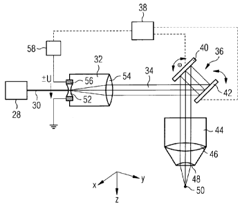
Reference will now additionally be made to Fig. 2. The laser apparatus shown
therein includes a femtosecond laser source 28 - constituted, for example, by
a
fibre laser - which generates pulsed laser radiation 30 with pulse durations
within
the femtosecond range and with a pulse-repetition rate which preferentially
lies
within the high two-digit kHz range up to the three-digit kHz range or even in
the
MHz range. The laser beam 30 which is generated is expanded by a multi-lens
beam expander 32. The expanded laser beam 34 subsequently reaches a scan-
CA 02765268 2011-12-12
- 8 -
ner 36 which has the task of deflecting the laser beam 34 in an x-y plane or-
thogonal to the direction of beam propagation (z-direction; cf. the coordinate
system that is also drawn in Fig. 2), and, by this means, of sweeping with the
laser beam the region of the eye to be treated. In the exemplary case that is
shown, the scanner 36 operates in accordance with the galvanometer principle
and is constituted by two tiltable deflecting mirrors 40, 42 which are
controllable
by a control unit 38. It will be understood that scanners operating in
accordance
with other principles (e.g. scanning by means of a suitably controllable
crystal)
are equally possible.
Situated downstream of the scanner 36 is an f-theta focusing objective 44 with
lenses 46, 48 which focus the laser beam onto a focus location 50. The
construc-
tion of the focusing objective 44 as an f-theta objective brings about a plane-
field
imaging in which, independently of the deflection angle of the laser beam, the
focus location 50 always lies in a flat plane orthogonal to the z-direction.
It will
be understood that the two-lens construction of the focusing objective 44
shown
in Fig. 2 is only exemplary. The objective 44 may have been constructed with
any
other number of lenses.
In the exemplary case that is shown, the beam expander 32 is constituted by a
Galilean telescope with an input lens 52 of negative refractive power (concave
lens) and with an exit lens 54 of positive refractive power (converging lens).
Alternatively, a Keplerian design of the telescope with two convex lenses is
also
possible. The entrance lens 52 is constructed as a lens of variable refractive
power, the refractive power of which is capable of being changed by means of
an
applied electrical driver voltage U. The achievable refractive-power
deviation of
the lens 52 preferentially lies distinctly above 10 dpt. The alteration of the
refrac-
tive power of the entrance lens 52 brings about an alteration of the
divergence of
the laser beam impinging on the exit lens 54, and hence a z-shift of the beam
focus 50. The entrance lens 52 is constructed as a liquid lens or as a liquid-
crystal lens and possesses an electrode arrangement 56 indicated only schemati-
cally in Fig. 2, to which the driver voltage is applied. Dashed lines
illustrate con-
trol connections between the control unit 38 and the deflecting mirrors 40, 42
as
well as a voltage driver 58 for the driver voltage U.
= CA 02765268 2011-12-12
- 9 -
The control unit 38 controls the voltage driver 58, and hence the electrode
volt-
age at the entrance lens 52, in accordance with the incision profile to be
realised
in the eye. A corresponding control program for the control unit 38 is saved
in a
memory which is not represented in any detail. In the case of liquid lenses,
which
are based on the principle of electrowetting, the refractive power of the lens
de-
pends on the square of the applied voltage. Control of the focal length of the
entrance lens 52 can therefore be effected with comparatively small voltage de-
viations in the case where this lens is constructed as a liquid lens. For
example,
with a voltage deviation of about 10 V, given suitable dimensioning of the en-
trance lens 52 a refractive-index deviation of about 10 dpt can readily be
obtained
(depending on the aperture and configuration of the electrostrictive lens 52).
In
this connection, given appropriate design the reaction-times of the liquid
lens may
lie within the range from a few tens of ms down to a few ms.
The focus of the f-theta objective 44 can consequently be repositioned in
times
that are necessary for an effective fast lenticular incision with an fs laser
system.
For example, a complete line scan can readily be carried out with a z-travel
of the
beam focus of about 100 pm within a period between about 10 ms and 40 ms.
With the use, according to the invention, of electrically controllable
variable-
refractive-power lenses in the beam expander 32, focus-travel frequencies are
consequently obtained such as are needed for meaningful application in the
course of the femtosecond lenticular extraction.
Liquid lenses currently available on the market, which operate in accordance
with
the principle of electrowetting, contain liquids that are highly transparent
within
the range from about 300 nm to 1300 nm. Accordingly, for the lenticular extrac-
tion (and also for other corneal incisions) use may be made both of the funda-
mental wavelength located within the low infrared region of a typical fs laser
source, and of a harmonic located within the UV region, for example the third
harmonic of this fundamental wavelength.
The UV wavelength is particularly suitable for refractive correction by means
of
femtosecond lenticular extraction, since the requisite accuracies of the beam
focusing are most likely to be attained with a wavelength around about 340 nm,
for example. For example, a focus diameter of no more than 1 pm is striven
for.
-
_ CA 02765268 2011-12-12
,
- 10 -
With an NIR wavelength such small focus diameters can be obtained only with
difficulty.
The design of the entrance lens 52 of the beam expander 32 in the form of a
variable-refractive-power lens has the further advantage that use can be made
of
a lens with a relatively small aperture, for example with a lens diameter
between
about 2 mm and 6 mm. As a result, the driver voltage can be kept small, and
faster switching-frequencies can be obtained.
Thirdly, the influence of any wavefront errors of the entrance lens 52 on the
achievable focus quality is sufficiently small. Liquid lenses currently
available on
the market exhibit, for example, only a wavefront quality of A/4, which in the
case
of use as a zoom lens in the focusing objective 44 would be insufficient for
achieving a diffraction-limited focus.
The lens of variable refractive power that is used within the scope of the
invention
should be transmitting at least in respect of fs laser pulses within the NIR
wave-
length region, preferentially at least between about 1000 nm and 1100 nm.
Overall it is desirable to enable a z-displacement of the beam focus of at
least
300 pm, preferentially at least 350 pm and still more preferably at least 400
pm,
solely by control of the lens of variable refractive power, without an
adjustment of
the focusing optics being additionally required for this purpose. Such a
maximal
focus travel should preferentially be achievable with a dioptric deviation of
the
lens of variable refractive power of at least 7.5 dpt, better at least 8 dpt
and bet-
ter still at least 8.5 dpt. The optical imaging system that images the
generated
laser beam onto the beam focus (i.e. telescope or beam expander, focusing ob-
jective and any optical elements arranged in between) should guarantee a corre-
sponding transmission ratio. The accuracy of adjustment of the lens of
variable
refractive power within the working-deviation range (which, for example, may
amount to about 9 dpt or about 10 dpt) should preferentially amount to at
least
3 %, better at least 2 % and, by way of example, approximately 1 %. A design
in
which a voltage deviation of about 1 V of a control voltage applied to the
lens of
variable refractive power brings about approximately a dioptric deviation of
about
1 dpt, and simultaneously a dioptric deviation of about 0.1 dpt brings about a
z-
- CA 02765268 2011-12-12
- 11 -
displacement of about 3-4 pm, can be obtained at any time with components
currently available on the market.