Note: Descriptions are shown in the official language in which they were submitted.
CA 02765496 2016-11-08
95256-22T
ENVIRONMENTALLY-FRIENDLY CEMENTITIOUS ARTICLES,
FORMULATIONS, METHODS OF MAKING AND USES
[0001]
BACKGROUND OF THE INVENTION
Field of the Invention
[0002] The present disclosure relates generally to fiber cement
manufacturing, and
more particularly, to systems and methods for reducing water usage in fiber
cement
manufacturing processes.
Description of the Related Art
[0003] Commercial fiber reinforced cementitious shaped articles, such
as fiber
cement building panels and exterior sidings, are usually manufactured using
large scale
cementitious forming processes. These large scale operations, such as
industrial-size Hatschek
process, typically require the use of millions of gallons of water as a
process aid. While some
efforts have been made to recycle and reuse the large volume of process water
in fiber cement
manufacturing, the efforts have been largely limited to installing filtration
systems to remove
particulates from the spent water or adjusting pH of the water for discharge.
The recycled
process water typically has high alkali content because cement continues to
leach alkali during
the cementitious forming process. As such, when the process water is reused,
the alkali metal
ions in the water can accumulate and detrimentally affect product properties.
[0004] Ion exchange systems have been used to treat water in both
industrial and
household applications to remove ions from water. For example, ion exchangers
have been
used in household water purification systems and in industrial applications
such as desalination
of sea water and removal of metals from plating solutions in semiconductor
processing.
However, conventional ion exchange systems are not equipped to handle, treat,
and maintain a
closed-loop circulation of the extremely high volume of process water with
complex chemical
make-up required in fiber cement manufacturing. Moreover, conventional ion
exchange
systems are not designed to treat extremely complex spent water
- 1 -
CA 02765496 2011-12-14
WO 2010/151450
PCT/US2010/038524
from cementitious forming processes in a manner such that the treated water
can provide
enhanced functional properties to the final product. In view of the foregoing,
there remains
a need for improved systems and methods for reducing water usage in large
scale fiber
cement manufacturing processes.
SUMMARY OF THE INVENTION
100051 Although making and using various embodiments are discussed in
detail
below, it should be appreciated that as described herein are provided many
inventive
concepts that may be embodied in a wide variety of contexts. Embodiments
discussed herein
are merely illustrative ways to make and use the invention, and do not limit
the scope of the
invention.
[0006] The preferred embodiments of the present invention provide a
closed-
loop system and method of treating spent process water in a large scale
cementitious shaped
article manufacturing process utilizing the Hatschek process, flow-on,
moulding, mazza
pipe, or the like. The cementitious articles made from the novel manufacturing
system may
be of a pre-formed shape such as a board, sheet, or panel. The articles may be
used as a
building product, useful as, for example, tile underlayment, siding, panel,
trim, fascia,
roofing, crown molding, decking, and fence. In addition to conserving water
and chemicals,
the preferred embodiments of the present invention provide fiber cement
articles with
unexpected, enhanced functional properties, including but not limited to,
enhanced strength
and durability, particularly after undergoing freeze-thaw conditions.
[0007] In one aspect, the preferred embodiments of the present invention
provide
a method of recycling process water from a cementitious forming process. The
method
comprises removing calcium, sodium, or potassium ions from the process water
to provide a
process water with a reduced metal ion content. The method further comprises
adding
calcium to the process water to produce a calcium enriched process water with
a reduced
metal ion content, and reintroducing at least a portion of the calcium
enriched process water
with a reduced metal ion content into the cementitious forming process. In one
embodiment, the calcium, sodium, and/or potassium ions are removed from the
process
water by an ion exchange process. Preferably, the ion exchange process
comprises a first
ion exchange resin having a weak acid functional group and a second ion
exchange resin
having a strong acid functional group. In one implementation, the weak
functional group is
¨CO2H and the strong acid functional group is ¨S03H.
2
CA 02765496 2011-12-14
WO 2010/151450 PCT/US2010/038524
[0008] In
another aspect, the preferred embodiments of the present invention
provide a cementitious shaped article manufacturing process. The process
comprises a
forming unit adapted to form a cementitious shaped article and a closed-loop
water
treatment system utilizing a plurality of ion exchangers. The forming process
discharges
spent process water containing calcium, sodium, and potassium ions. The ion
exchangers
are adapted to remove at least one of the ions present in the spent process
water. In one
embodiment, at least one of the ion exchangers in the closed-loop water
treatment system is
adapted to remove calcium ions from the process water. In another embodiment,
the ion
exchangers are sequentially arranged such that the ion exchangers are adapted
to first
remove multivalent ions before removing monovalent ions. In some embodiments,
cation
resins are used to remove anions such as S042- and Cl- from the process water.
In some
other embodiments, the process comprises at least one ion exchanger adapted to
add
calcium back to the process water after calcium ions have been removed by
another ion
exchanger.
[0009] In yet
another aspect, the preferred embodiments of the present invention
provide a system for manufacturing a cementitious building article. The system
comprises a
faulting process and an alkali removal process incorporating a partially
closed-loop water
recycling system. Preferably, the alkali removal process comprises at least
two sets of ion
exchangers operating in parallel. Preferably, the forming process is in
cooperation with the
alkali removal process such that at least a portion of the water exiting the
forming process is
recycled through the alkali removal process which results in process water
having a reduced
alkali content. In one embodiment, the alkali removal process is adapted to
receive water
discharged from the forming process at a flow rate of about 8,000 to 150,000
gallons per
hour.
[0010] In yet
another aspect, the preferred embodiments of the present
invention provide a cementitious shaped article prepared by a cementitious
forming process
carried out in the presence of water which has been recycled according to the
methods and
systems described herein. In one embodiment, the cementitious shaped article
is a fiber
cement building panel or siding formed by a Hatschek process using recycled
process water
having a reduced alkali content and an enriched calcium ion content. The
cementitious
shaped article thus formed has a higher MOR and tensile strength, particularly
after
undergoing freeze-thaw conditions, than an equivalent article formed by a
comparative
3
manufacturing process that does not use recycled process water having a
reduced alkali content
and/or enriched calcium ion content.
[0010a] In an aspect, there is provided a method of recycling spent process
water
from a fibre cement forming process comprising: removing calcium, sodium, and
potassium
ions from the spent process water to provide a process water with a reduced
metal ion content,
wherein calcium ions are first removed before sodium and potassium ions are
removed from
the spent process water; converting the calcium ions to a calcium salt; adding
the calcium salt
to the process water to produce a calcium enriched process water with a
reduced potassium and
sodium ion content; and reintroducing at least a portion of the calcium
enriched process water
with said reduced potassium and sodium ion content into the fibre cement
forming process.
[0010b] In an aspect, there is provided a fibre cement shaped article
manufacturing
system, comprising: a forming unit adapted to form a fibre cement shaped
article, wherein the
forming unit discharges spent process water containing calcium, sodium, and
potassium ions;
and a closed-loop water treatment system in communication with the forming
unit, said water
treatment system comprising: a plurality of ion exchangers, wherein at least
one of the ion
exchangers comprises a weak acid functional group adapted to remove the
calcium ions present
in the spent process water and a further ion exchanger comprising a strong
acid functional
group adapted to remove the sodium and potassium ions present in the spent
process water; an
4
CA 2765496 2018-03-13
ion exchanger regeneration system adapted to convert the calcium ions removed
in the first ion
exchange resin to a calcium salt; and transport means to add the calcium salt
to the process
water with reduced metal ion content to produce a calcium enriched process
water with a
reduced potassium and sodium ion content; and means to reintroduce at least a
portion of the
calcium enriched process water with the reduced potassium and sodium content
into the
forming unit.
BRIEF DESCRIPTION OF THE DRAWINGS
10011] The drawing figures are not necessarily to scale and certain
features may be
shown exaggerated in scale or in somewhat generalized or schematic form in the
interest of
clarity and conciseness.
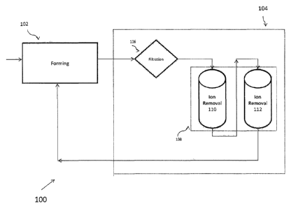
[0012] FIGURE 1 provides a general schematic illustration of a fibre
cement
manufacturing process of one preferred embodiment which incorporates a closed-
loop process
water recycle and treatment system;
[0013] FIGURE 2 schematically illustrates a set of ion exchangers 200
according to
one preferred embodiment;
[0014] FIGURE 3 is a schematic diagram of a cementitious shaped article
manufacturing system of another embodiment;
[0015] FIGURE 4 is a schematic diagram of a cementitious shaped article
manufacturing system of yet another embodiment;
[0016] FIGURE 5 is a schematic diagram of a cementitious shaped article
manufacturing system of yet another embodiment;
[0017] FIGURE 6 is a schematic diagram of a cementitious shaped article
manufacturing system of yet another embodiment;
[0018] FIGURE 7 is a schematic diagram of a cementitious shaped article
manufacturing system of yet another embodiment;
[0019] FIGURE 8 is a schematic diagram of a cementitious shaped article
manufacturing system of yet another embodiment;
[0020] FIGURE 9 schematically illustrates an embodiment of a multistage
alkali
removal system which includes an ion addition step; and
- 4a -
CA 2765496 2017-06-16
[0021] FIGURE 10 schematically illustrates an embodiment of a set of
ion
exchangers which includes an ion addition step.
DETAILED DESCRIPTION OF THE PREFERRED EMBODIMENT
[0022] Figure 1 schematically illustrates a fibre cement manufacturing
system 100
of one preferred embodiment, which incorporates a novel closed-loop spent
water
- 4b -
CA 2765496 2017-06-16
CA 02765496 2011-12-14
WO 2010/151450
PCT/US2010/038524
recycle and treatment process that reduces water and chemical usage, and also
enhances the
functionality of the formed product. As shown in Figure 1, the system 100
generally
comprises a forming unit 102 adapted to form a fiber cement shaped article,
and a closed-
loop water treatment system 104 adapted to treat at least a portion of the
spent process water
and recirculate the treated process water back to the forming unit 102. The
forming unit 102
may include Hatschek, Magnani process, flow-on, or any other water based fiber
cement
forming processes known in the art. In some embodiments, the forming unit 102
comprises
one or more slurry vats, a running felt, a formation cylinder and a conveyer.
[0023] As further shown in Figure 1, the closed-loop water treatment
system 104
comprises a filtration device 106 and a multistage alkali removal system 108.
In one
embodiment, the filtration device 106 is designed to remove residues, such as
fine
particulate matters, fibers, aggregates, from the process water before alkali
treatment, thus
preventing blockage and increases usage time of the alkali treatment steps. In
one
implementation, the filtration device 106 comprises multiple filtration units
in series, which
may have capabilities to screen different sizes of residue and process water.
The filtration
units are, in some embodiments, arranged sequentially in series so that larger
particulate
matters are removed before finer ones. The sequence helps distribute the
particle loading
across the units. A filtration unit may be a strainer, screen, disk filter,
bag filter, sand filter,
cartridge filter, or similar.
[0024] The multistage alkali removal system 108, which receives the
spent
process water after filtration, is specifically designed to remove harmful
ions from the water
while retaining useful ions that may enhance product functionality. Because
cementitious
forming processes are usually conducted in a highly alkaline environment, the
spent process
water usually has high alkali content and contains a large amount of
monovalent and
multivalent ions. Specifically, the inventor has found that the presence of
certain
monovalent ions, such as Na+ and K+, in the spent process water could have
damaging
effects on the product if the water is reused. In the same token, the inventor
has found that
the presence of certain multivalent ions such as Ca2+ in the water can have a
surprisingly
positive effect on product functionality and performance. Thus, the multistage
alkali
removal system 108 is preferably designed to selectively remove certain
monovalent ions,
such as Na + and K+, so that the treated process water has a reduced alkali
content and
CA 02765496 2011-12-14
WO 2010/151450 PCT/US2010/038524
contains a minimal level of Na+ and K+ but a high level of Ca2+. In some
embodiments, the
multistage alkali removal system 108 is also designed to selectively remove
chromium (Cr).
[0025] As shown in Figure 1, the multistage alkali removal system 108
generally
includes an ion removal step 110 and 112. In some embodiments, the multistage
alkali
removal system 108 preferably comprises a series of ion exchanger units that
are configured
in a sequential order such that through the ion removal step, multivalent
ions, such as Ca+2,
Cr(VI), are removed before monovalent ions, such as K+ and Nat. Subsequent to
the
removal of these ions, certain multivalent ions such as Ca+2 are then added
back to the
process water before it is reused in the forming process. The multivalent ions
are first
removed in order to facilitate removal of the monovalent ions, otherwise the
multivalent
ions will likely saturate the resin bed and prevent effective removal of the
monovalent ions.
[0026] The alkali removal system generally operates by stoichiometric
and
chemically reversible reactions between alkali ions in the spent process water
and acidic
ions within the ion exchanger units which form a salt. The ion exchanger units
comprise
one or more synthetic resins placed in series or in parallel to which acidic
ions are bound on
the active sites of the resin. Synthetic resins include cation exchange resins
for removal of
alkali cations and may also include anion exchange resins for removal of one
or more
anions. Examples of suitable synthetic resins include but are not limited to
polystyrenic gel,
polystyrene cross-linked with divinylbenzene, or long chain polymeric beads
with
carboxylic or sulfuric acid functional groups. In some embodiments, each set
of ion
exchangers may include at least one exchanger having a weak acid functional
group and at
least one exchanger having a strong acid functional group.
[0027] Figure 2 schematically illustrates a set of ion exchangers 114
according
to one preferred embodiment. As shown in Figure 2, the set of ion exchangers
114 has four
ion exchange stages or units, each designed to remove specific ions. The first
ion exchanger
116 has a weak acid resin bed selected to remove alkaline earth ions such as
Ca+2 from the
process water. The weak acid resin preferably has sites with one or more weak
acid
functional groups, such as carboxylic functional group, acetyl functional
group, phosphoric
functional group, boracic functional group. The second and third ion
exchangers'118, 120
each have a strong acid resin bed selected to remove alkali ions such as K+
and Na+. Strong
acids may have functional groups such as a sulfonic group, perchloric group,
hydrobromic
group, hydrochloric group, nitric group. The fourth unit 122 can be a strong
acid resin to
6
CA 02765496 2011-12-14
WO 2010/151450 PCT/US2010/038524
remove K+ and Nat, or can be a strong base resin to remove S042" and cr. As
further
shown in Figure 2, sulfuric acid 124 is used to back flush or regenerate each
resin bed when
the resin is saturated. In one embodiment, calcium ion removed in the first
ion exchanger
116 is converted to calcium sulfate. The calcium sulfate is then transported
to reintroduce
calcium ions back to the process water. The inventor has found that addition
of calcium to the
process water surprisingly enhances the functionality and performance of the
final product in a
manner to be described in greater detail below.
[0028] Figure 3 is a schematic diagram of a cementitious shaped article
manufacturing system of another representative embodiment. A formulation 126
enters a
typical water based composite forming process at box 128 yielding one or more
formed
composite articles 136 shaped in any of a number of shapes as desired. Water
used with
water forming process 128 exits as alkali process water 130 and is fed into an
alkali removal
process at box 132. The alkali removal process may be an ion exchange process
or any
other process designed to remove alkali content from the water. After
processing at box
132, water exits the alkali removal process as water 134 having reduced amount
of alkali
and is available for reentering the water based composite forming process at
box 128.
Process water 130 exiting box 128 may do so at one or more exit ports.
Similarly, box 132
may have one or more exit ports for the outflow of water 134. Moreover, water
134
entering box 128 may enter via one or more entry ports. Multiple entry and
exit ports will
allow flow water when desired to be regenerated in process to maximize
efficiency of the
system. In addition, water may be tested at one or more exit ports to ensure
alkali content is
at a desired level. Generally, water leaving the one or more exit ports from
box 132 will
return to box 128. However, some water may be re-used in another portion of
the system.
Under the design shown in Figure 3, water may be recycled in a completely
closed-loop
system or a partially closed loop system. When one or more water based forming
processes
128 are in operation, each may have one or more exit ports that diverge to the
same alkali
removal process box 132. In one form, process water from the forming process
128 is
passed through a multi-stage alkali removal process. This alkali removal
process prevents
build up of alkali ion, such as sodium or potassium, in the closed-loop
system.
[0029] In some embodiments, the multistage alkali removal system is made
up
of more than one alkali removal sets designed to operate in parallel or in
series in the event
that one of the sets requires maintenance, cleaning, testing, and the like. An
example is
7
CA 02765496 2011-12-14
WO 2010/151450
PCT/US2010/038524
depicted in Figure 4, in which box 138 and 140 are both alkali removal sets,
each having a
shut-off valve at 138a and 140a, respectively. Either one or both shut-off
valves may be
open allowing alkali water to flow to either one or both alkali removal
processes. Removal
set 138 and removal set 140 may further include one or more flow ports
depicted at 142 that
allow some or all of the water from one removal set to pass to the other
removal set
allowing for even further ion removal. For example, some or all of water from
removal set
138 may exit via 142 to removal set 140 and after alkali processing will exit
removal set 140
via exit port 140b to then return to box 128. Should only a portion of the
water be shunted
via 142, the remainder will exit via exit port 140b. Generally, water from
exit port 140b
will return to box 128. However, some water may be re-used in another portion
of the
system. Similarly, some or all of water that enters removal set 138 may exit
via 142 to
removal set 140 and exit removal set 140 via exit port 140b to then returns to
box 128.
[0030] Another example is shown in Figure 5, which depicts two multi-
stage
exchangers, 144a and 144b, operating in parallel. Process water 146 may enter
multi-stage
exchanger 144a when exchanger 144b is off-line, generally via shut-off valves
placed
between 146 and 148. Similarly, process water 146 may enter multi-stage
exchanger 144b
when exchanger 144a is off-line, generally via shut-off valves placed between
146 and 150.
Exchanger 144a includes at least two exchangers, at least one weak acid
exchanger 150 and
at least one strong acid exchanger 152. Similarly, exchanger 144b includes at
least two
exchangers, at least one weak acid exchanger 148 and at least one strong acid
exchanger
154. After water flows through one or more exchangers, the output water 156
exiting the
one or more exchangers will have less alkali ions and will be able to be
recycled back to the
forming process for continuous manufacturing of composite articles.
Optionally, some or all
of the water may by-pass the alkali removal process. This is depicted
schematically in
Figure 6. For example, a portion of water 158 may be diverted through port 160
into
exchanger 162, exiting the exchanger at 164. Water 158 may be clean or
untreated water
and may become recombined with less alkali water as water 166.
[0031] Alkali water passing through an activated exchanger leads to the
formation of salt on the active sites of the resin beds. Over time, as the
amount of salt
accumulates, the number of active sites is reduced, the efficiency of the
resin bed is
adversely affected. A resin bed is regenerated or reactivated by acidification
of the resin.
Generally, this involves taking the exchanger off-line and introducing acids
to the
8
CA 02765496 2011-12-14
WO 2010/151450 PCT/US2010/038524
exchanger. Reactivation occurs generally as depicted in Figure 7 in which an
acid 170 is
introduced into the flow line and is run through exchanger 172 while it is
shut off from the
process water line. Activation by an acid on a used resin leads to the
discharge of salts from
the resin bed and the replacement of acidic functional groups on active sites
of the resin.
The discharge fluid 174 exiting exchanger 172 after acidification is a saline
solution that
may either be re-used in another portion of the system, in an alternative
system or
discharged as a weak salt without requiring further processing. Suitable acids
for
regeneration of the weak or strong acid resin beds include nitric acid,
hydrochloric acid,
fluoroantimonic acid, carborane, triflic acid, as examples. Other acids for
regenerating
weak acid resin bed include but are not limited to acetic acid, citric acid,
boric acid,
phosphoric acid, or hydrofluoric acid. Acid concentrations may range from
about 0.05M to
about 0.5M. The general range of times for regeneration is typically from 1
hour to 10
hours.
[0032] Typically in use and as described herein, more than one alkali
removal
process is placed in parallel so that at least one is in operation while
another is taken off line
when reactivation is required. This allows the overall manufacturing system of
composite
articles to operate in a continuous fashion without interruption, thus
reducing waste and
efficiency due to start-up and shut-down times. In operation, the same acid
may be used to
regenerate exchangers with either the strong acid or weak acid resin beds.
[0033] It has been found unexpectedly that articles formed from the
system
described herein have improved characteristics as compared with alternative
articles made
from a water recycling process that lack an alkali removal step. For example,
articles
described herein generally exhibit an improvement in the modulus of rupture at
saturation
(MOR) of about 10%, to 30% as compared with the same article made from a
system that
lacks an alkali removal process. In addition, articles prepared via
manufacturing processes
described herein will exhibit a MOR of greater than about 8 MPa, or greater
than about 8.5
MPa, or greater than about 9 MPa, or greater than about 9.5 MPa, or greater
than about 10
MPa. Articles prepared via manufacturing systems described herein will also
exhibit an
improvement in a tensile strength from about 10%, or about 20%, or about 30%
as
compared with the same article made from a system that lacks an alkali removal
process.
[0034] Articles described in certain preferred embodiments are generally
cementitious and comprise a hydraulic binder, at least one silica source, and
one or more
9
CA 02765496 2011-12-14
WO 2010/151450
PCT/US2010/038524
fiber sources for reinforcement. Formulations may further comprise one or more
additives
such as one or more density modifiers, water repelling or hydrophobic
additives, and/or
biocides. The article surfaces may be further finished using methods, such as
sanding,
brushing, sand-blasting, stamping, embossing, machining and the like. The
article may be
air cured, cured in an autoclave, or using virtually any known or available
curing method or
system. The article may be treated with one or more coating treatments. The
article may
also be cut into other shapes and sizes.
[0035] Articles prepared via manufacturing system described herein
are less
affected by moisture damage, especially under freeze-thaw performance, as
compared with
= the same article made from a system that lacks an alkali removal process.
Thus, such
articles provided as described herein retain their thickness and shape better
than articles
made from conventional water-based manufacturing method that recycles water
but does not
include an alkali removal process. Articles prepared as described herein will
last about 10
cycles longer, or about 15 cycles longer, or about 20 cycles longer than
articles made from a
similar system that does not include alkali removal as described herein.
Performance
parameters, such as MOR, MOE, and moisture movement, moisture content and
freeze-thaw
performance, are characterized by ASTM C1185, ASTM C1186 and ASTM D1037,
respectively.
[0036] Articles described are manufactured using any water-based
manufacturing system and, thus, may be formed as a panel or sheet and may be
further
configured for use in exterior or interior applications. As a panel or sheet,
an article
described herein is generally defined by at least two generally planar faces
that are exterior
surfaces. An article described herein also has one or more perimeter edges
generally
defined as an exterior surface having a surface area less than the smallest
face or less than
the smaller edge. Additional configurations for articles described herein,
include but are not
limited to a fence, tile underlayment, siding, trim, fascia board, roofing
tile, decking, and the
like, as examples. The system described herein do not limit the type of
article that is
manufactured and unexpectedly conserves resources as well as provides a
mechanically
better building article than what is provided by comparative systems that have
tried to
conserve resources but do not include an alkali removal process as described
herein. The
systems described herein do provide for a cementitious article having a low
alkali content.
Articles may be further shaped and sized or cut into desired shapes and sizes.
CA 02765496 2011-12-14
WO 2010/151450
PCT/US2010/038524
[0037] Article surfaces may be substantially flat having a smooth
texture and/or
a rough texture. In some embodiments, the texture on one or more surfaces may
include an
artistic design, such as a name and/or a specific marking that is uniform or
random. In some
embodiments, a surface may imitate a known texture, such as wood grain or
stone
appearance. In addition or as an alternative, one or more surfaces of an
article may have one
or more portions that protrude outwards or inflect inwards. The protruded or
inflected
portions may include a functional portion or may serve as a design feature, or
combinations
thereof. Examples of such surfaces are a key line, a bead, and a groove.
[0038] The thickness of articles described herein, measured as the
shortest
distance between two surfaces, may be less than about 50 mm. In some
embodiments, the
thickness may be less than about 35 mm, or less than about 25 mm. In some
embodiments,
the thickness is less than about 6 mm. Such thinner building products, such as
panels or
sidings, allow for the same area of coverage with a reduced amount of raw
materials. In
some embodiments, the thickness may vary across the article in view of various
protrusions,
inflections and/or hollowed and/or grooved regions. Some embodiments or
applications
provide for thicker articles. The thickness maybe more than about 35 mm, or
more than
about 40 mm, or more than about 45 mm. Such thicker building products may
provide
stronger and more architecturally appealing products where desired.
[0039] When an article described herein is configured as a long sheet or
panel,
the length of the panel is the longest distance between two points on the same
surface of all
exterior surfaces. Often such articles are greater than about 3.5 meters (m)
in length. In
some embodiments, the length may be greater than about 5 m, or greater than
about 6 m. It
has been found that longer building products, especially trim, decking or
fascia, may allow
for quicker installation and will have fewer joints between consecutive
pieces, which aids in
installation.
[0040] In some embodiments, the articles described are configured as a
narrow
sheet or panel. The width of the panel, measured as a distance between edges,
is in some
embodiments less than about 360 mm. The width may also be less than about 160
mm or
less than about 100 mm.
[0041] One of the challenges in incorporating an ion exchange system in
a
commercial fiber cement manufacturing process to treat and recirculate spent
process water
is designing a system that can handle the large volume of process water with
complicated
11
CA 02765496 2011-12-14
WO 2010/151450
PCT/US2010/038524
chemical composition. Figure 8 shows the flow diagram of a fiber cement
manufacturing
process of a preferred embodiment which successfully incorporates an ion
exchange system
to treat the spent process water by dividing the water into separate process
streams and
controlling the flow rate of each stream.
[0042] As shown in Figure 8, the process water exiting the forming unit
102 is
divided into a recycle stream 176 and a waste stream 178. Water in the recycle
stream 176
is directed to the multistage alkali removal system 104. The recycle stream
176 is first
directed to the filtration process 106, which be a single process before the
parallel alkali
removal steps 108, or a filtration process in each of the parallel alkali
removal sets, or a
combination thereof.
[0043] After completing the filtration process 106, a first portion 176a
of the
recycle stream is recirculated back to the forming unit 102 while a second
portion 176b is
recycled through the alkali removal process 108 for alkali removal treatment
before entering
back into the forming unit 102. With the arrangement of multiple parallel
alkali removal
sets, not all of the sets are in operation at any time, thus leaving at least
one set in a stand-by
mode. The ion exchange units collect the alkali ion from the process water,
and thus over
time will gradually become saturated and needs to be taken offline for cleaned
out or
regenerate. The stand-by set is then put back on-line, with the process water
redirected
through it for treatment.
[0044] The treated recycled stream 176b may have a flow rate of 5 to
100% of
the total process water flow rate. The waste stream 178 of the process water
exiting the
forming process can range from 0 to 95% of the process water flow rate. The
first portion
176a of the recycled stream ranges from about 2% to 70% of the total process
water flow
rate and may be recycled directly back to the process without going through
the alkali
removal treatment. In one embodiment, water exits the forming process at a
flow rate of
about 8,000 to 150,000 gallons per hour, more preferably at about 50,000
gallons per hour.
In another embodiment, the recycle stream enters the alkali removal sets at a
flow rate of
about 4800 to 100,000 gallons per hour, more preferably at about 30,000
gallons per hour.
In yet another embodiment, the portion of recycle stream that is recycled back
to the
forming process without being treated in the alkali removal process has a flow
rate of about
1600 to 150,000 gallons per hour, more preferably at about 10,000 gallons per
hour.
12
CA 02765496 2016-11-08
95256-22T
100451 When one of the parallel ion exchange sets is offline for
cleaning, the resin
bed in each ion exchange unit may be regenerated by back flush by an acid
solution to restore
the acid functional group sites on the resin bed. The acid solution in some
embodiments is
selected to have at least one functional group of carboxylic group, acetyl
group, phosphoric
group, sulfonic group, perchloric group, hydrobromic group, hydrochloric
group, nitric group
or combination thereof. The ion exchange units that are designed to remove
monovalent ions
are referred herein as to have a strong acid resin bed. The molar
concentration of the acid
solution for strong acid resin bed may be 0.3 to 0.5M. The ion exchange units
that are designed
to remove multivalent ions are referred to here as to have a weak acid resin
bed. The weak acid
resin bed are regenerated by an acid solution with molar concentration of 0.05
to 0.5M. It has
been found that the acid functional groups on the resin beds can be restored
within 1 to 10
hours of continuous back-flushing.
[0046] Figure 9 illustrates another implementation of the multistage
alkali removal
system 108 which preferably includes an ion addition step 194. In some
embodiments, ions are
first removed using a series of ion exchanger units 110 that are configured in
a sequential order
such that through the ion removal step, multivalent ions, such as Ca+2, are
removed before
monovalent ions, such as K+ and Nat. Subsequent to the removal of these ions,
certain
multivalent ions such as Ca+2 are then added back to the process water in the
ion addition step
194 before it is reused in the forming process. The multivalent ions are first
removed in order to
facilitate removal of the monovalent ions, otherwise the multivalent ions will
likely saturate the
resin bed and prevent effective removal of the monovalent ions.
[0047] The alkali removal system generally operates by stoichiometric
and
chemically reversible reactions between alkali ions in the spent process water
and acidic ions
within the ion exchanger units which form a salt. The ion exchanger units
comprise one or
more synthetic resins placed in series or in parallel to which acidic ions are
bound on the active
sites of the resin. Synthetic resins include cation exchange resins for
removal of alkali cations
and may also include anion exchange resins for removal of one or more anions.
Examples of
suitable synthetic resins include but are not limited to polystyrenic gel,
polystyrene cross-linked
with divinylbenzene, or long chain polymeric beads with carboxylic or sulfuric
acid functional
groups. In some embodiments, each set of ion exchangers may include at least
one exchanger
- 13 -
CA 02765496 2016-11-08
95256-22T
having a weak acid functional group and at least one exchanger having a strong
acid functional
group.
[0048] As shown in Figure 10, the set of ion exchangers 114 can have
four ion
exchange stages or units, each designed to remove specific alkali ions. The
first ion exchanger
116 has a weak acid resin bed selected to remove alkaline earth ions such as
Ca+2 from the
process water. The weak acid resin preferably has sites with one or more weak
acid functional
groups, such as carboxylic functional group, acetyl functional group,
phosphoric functional
group, boracic functional group. The second, third, and fourth ion exchangers
118, 120, 123
each have a strong acid resin bed selected to remove alkali ions such as K+
and Nat. Strong
acids may have functional groups such as a sulfonic group, perchloric group,
hydrobromic
group, hydrochloric group, nitric group. As further shown in Figure 2,
sulfuric acid 124 is used
to back flush or regenerate each resin bed when the resin is saturated with
salt. In one
embodiment, calcium ion removed in the first ion exchanger 116 is converted to
calcium
sulfate. The calcium sulfate is then transported to the fourth ion exchanger
123 to reintroduce
calcium ions back to the process water. The inventor has found that addition
of calcium to the
process water surprisingly enhances the functionality of the final product.
[0049] Following is an example of products manufactured using the system
described in Figure 8. In the forming process, raw materials were mixed in a
mixing vat, such
as that in a Hatcheck machine. A slurry was made by combining 4440 lb/h of
ordinary Portland
cement, 12000 lb/h of cellulose fiber, 63000 lb/h of ground silica, 150 lb/h
of anionic poly-
acrylamide and 60,000 gallons/h of fresh water. The slurry was introduced into
the bottom of
four slurry vats in the Hatschek machine. A running felt collected solid
matter and some water
depositing thin layers of slurry onto a formation cylinder. Multiple layers
were accumulated on
the formation cylinder until an overall material thickness was achieved. In
this example, the
thickness was about 127 mm; however thicknesses, as described earlier, may
readily be varied
with said forming process and machine. The layered material was cut at
periodically to create
articles at a desired length. The layered material was then transferred to a
take-off conveyor, at
which point the layered material left the forming process.
[0050] Water from the slurry vats in the Hatschek machine had a flow
rate of about
50,000 gallons/h. The water, also referred to as over-flow process water, had
a steady
- 14 -
CA 02765496 2011-12-14
WO 2010/151450
PCT/US2010/038524
state alkali level of about 1300 ppm. This flow rate may be adjusted and may
range from
about 8,000 gal to 150,000 gal. The overflow process water was divided into at
least three
streams. A first stream having a flow rate of about 30,000 gallon/h was
directed to an alkali
removal process. This flow rate may be adjusted and may range from 4,800 gal
to 100,000
gal. A second stream having a flow rate of about 10,000 gallon/h was combined
with output
from the alkali removal process prior to reentry back into the forming
process. This flow
rate may be adjusted and may range from 1,600 gal to 150,000 gal. A third
stream having a
flow rate of about 10,000 gallon/h was discharged from the process. This flow
rate may be
adjusted and may range from 1,600 gal to 150,000. Of course flow rates, as
described, are
adjustable and may be altered as desired. Adjustment of flows rates would be
understood
and could be performed by one of ordinary skill in the art.
[0051] In the alkali removal process, solid particles greater than 5 mm
were
removed from the first stream using a solid-liquid separator. A solid liquid
separator used
in this example was a series of cartridge filters. However, alternative
separators may be
implemented without undue experimentation. The stream was then directed to a
set of six
alkali resin beds. The six resin beds include two parallel sets of three beds
in series. One
set is sufficient to treat the water stream and often only one set may be in
operation at a
time. After every 8 hours of operation, the set of resin beds that were in use
were subjected
to regeneration, hence taken off-line, while the process water stream was
redirected to the
second parallel set. In each set of three resin beds in series, the first bed
includes resin with
weak acid functional groups on its active sites which included a carboxylic
acid functional
group, the second and third beds had a strong acid functional groups on its
active sites that
included a sulfonic acid functional group. When in operation, the alkali ions
in the process
water stream reacted with the acid functional group in each of the resin beds
and formed
salts on the active site, leaving the process water exiting the set of resin
beds substantially
free of alkali ions. Once the process water was treated the treated water
stream was
combined with the second stream described previously and recycled back to the
bottom of
the slurry vats in the forming process.
[0052] For regeneration of the resin beds, the weak acid resin bed was
subjected
to a flow of sulfuric acid at a concentration of about 0.7% at a flow rate of
about 2500
gallon/h for about 2 hours. The strong acid resin beds were each subjected to
a flow of
sulfuric acid at a concentration of about 7% at a flow rate of about 230
gallon/h for about 2
CA 02765496 2011-12-14
WO 2010/151450
PCT/US2010/038524
hours. Ranges of concentration and flow acid may vary as desired from about
0.5% in the
first resin bed to up to 40% in the second resin bed. Examples include about
0.5%
concentration in the weak acid bed followed by about 8% in the strong acid bed
or about 5%
in the weak acid bed followed by about 11% in the strong acid bed or about 4%
in the weak
acid bed followed by about in the strong acid bed 12%. With increasing acid
strength (e.g.,
concentration), regeneration will typically be of a shorter duration.
Adjustment of flows
rates and acid concentration would be understood and could be performed by one
of
ordinary skill in the art. During regeneration, acid functional groups replace
the salt affixed
to the resin beds. The discharge solution after regeneration is a relatively
weak salt solution,
an example of which includes calcium sulfate in the example described above,
which may
be reused separately for one or a number of purposes.
100531 The layered material formed from the forming process was further
embossed with a decorative pattern by a roller, pressing on the material with
a pressure of
about 110 Psi. The material was autoclaved at a saturated temperature of
greater than 180
C for about 12 hours. The material was then tested according to ASTM methods
disclosed
previously and had an MOR of 10.2 MPa.
100541 In a comparative system, a forming process described above
operated in
the absence of an alkali removal process. Here, first and second water streams
from the
overflow process water were combined and recycled directly back to the bottom
of the
slurry vats. It was found that the alkali concentration in the process water
continued to rise
over time. After 6 hour of operation, the alkali level had reached 3600 ppm.
The product
produced at this point was tested as described above according to ASTM methods
and found
to have an MOR of 7.6 MPa, significantly lower than that of the product sample
formed
when an alkali removal process was in cooperation with the fonning process.
100551 The TABLE outlines some quantitative differences in product
performance of articles prepared by either the systems described herein or an
alternative
system that does not include an alkali removal process as described herein.
TABLE. Representative properties of formed samples.
With alkali removal Without alkali
removal
MOR (MPa) according to 10.2 7.6
16
CA 02765496 2011-12-14
WO 2010/151450 PCT/US2010/038524
ASTM 1186
Tensile strength (MPa) 2.17 1.35
according to ASTM 1186
Tensile strength at 20 freeze- 1.33 1.06
thaw cycles according to
ASTM D1037 (MPa)
[0056] Although the foregoing description of certain preferred
embodiments
has shown, described and pointed out the fundamental novel features of the
invention, it
will be understood that various omissions, substitutions, and changes in the
form of the
detail of the invention as illustrated as well as the uses thereof, may be
made by those
skilled in the art, without departing from the spirit of the invention.
Consequently, the
scope of the invention should not be limited to the foregoing discussions.
-17-