Language selection

Search

Patent 2765508 Summary

Third-party information liability

Some of the information on this Web page has been provided by external sources. The Government of Canada is not responsible for the accuracy, reliability or currency of the information supplied by external sources. Users wishing to rely upon this information should consult directly with the source of the information. Content provided by external sources is not subject to official languages, privacy and accessibility requirements.

Claims and Abstract availability

Any discrepancies in the text and image of the Claims and Abstract are due to differing posting times. Text of the Claims and Abstract are posted:

  • At the time the application is open to public inspection;
  • At the time of issue of the patent (grant).
(12) Patent: (11) CA 2765508
(54) English Title: FLOW OUTPUT NOZZLE FOR CENTRIFUGAL PUMP
(54) French Title: BUSE DE SORTIE D'ECOULEMENT POUR POMPE CENTRIFUGE
Status: Granted
Bibliographic Data
(51) International Patent Classification (IPC):
  • F04D 29/42 (2006.01)
  • F04D 29/44 (2006.01)
(72) Inventors :
  • HUNJAN, HARJIT S. (United States of America)
  • BURTON, MICHAEL S. (United States of America)
(73) Owners :
  • SUNDYNE, LLC (United States of America)
(71) Applicants :
  • SUNDYNE CORPORATION (United States of America)
(74) Agent: NORTON ROSE FULBRIGHT CANADA LLP/S.E.N.C.R.L., S.R.L.
(74) Associate agent:
(45) Issued: 2014-09-09
(86) PCT Filing Date: 2010-05-06
(87) Open to Public Inspection: 2010-12-23
Examination requested: 2011-12-13
Availability of licence: N/A
(25) Language of filing: English

Patent Cooperation Treaty (PCT): Yes
(86) PCT Filing Number: PCT/US2010/033826
(87) International Publication Number: WO2010/147709
(85) National Entry: 2011-12-13

(30) Application Priority Data:
Application No. Country/Territory Date
12/485,991 United States of America 2009-06-17

Abstracts

English Abstract

A flow outlet for a pump includes a pocket section which defines a pocket section diameter. A throat section downstream of the pocket section, the throat section defines a throat section diameter less than the pocket section diameter.


French Abstract

Selon l'invention, une sortie d'écoulement pour une pompe comprend une section de poche qui définit un diamètre de section de poche. Une section de gorge se trouve en aval de la section de poche, la section de gorge définissant un diamètre de section de gorge inférieur au diamètre de section de poche.

Claims

Note: Claims are shown in the official language in which they were submitted.


CLAIMS

1. A flow outlet for a pump comprising:
a pocket section defined by a pocket section diameter, a pocket section
length, and a
volute width extending in a direction transverse to said pocket section
diameter; and
a throat section downstream of said pocket section, said throat section
defined by a
throat section diameter and a throat section length, said throat section
diameter being less
than said pocket section diameter, and wherein said pocket section length is
defined by an
angle between a pump axis of rotation and an intersection between the pocket
section and
the throat section along an outlet axis defined by the throat section, and
wherein said pocket
section diameter is less than or equal to said volute width of the pocket
section, and wherein
said throat section diameter is less than or equal to approximately 0.3 times
said pocket
section diameter.
2. The flow outlet as recited in claim 1, wherein said flow outlet is
defined along an
axis transverse to an axis of rotation of an impeller.
3. The flow outlet as recited in claim 1, further comprising a transition
section
downstream of said throat section, said transition section defining a stepped
transition
section.
4. The flow outlet as recited in claim 1, further comprising a transition
section
downstream of said throat section, said transition section defining an angled
transition
section.
5. The flow outlet as recited in claim 1, further comprising a transition
section
downstream of said throat section, said transition section defining a
transition section
diameter that is approximately 1.6 to 2.1 times said throat section diameter.
7


6. The flow outlet as recited in claim 1, further comprising a transition
section
downstream of said throat section, wherein a transition section length (Lt) is
defined by Lt
0.55Ld-Lth where Lth is throat section length and Ld is a diffuser section
length of a
diffuser section downstream of said transition section.
7. The flow outlet as recited in claim 6, wherein sides of said diffuser
section define a
diffuser section angle.
8. The flow outlet as recited in claim 1, wherein said pocket section and
said throat
section are formed within a single-piece nozzle that is positioned within the
flow outlet.
9. The flow outlet as recited in claim 8, wherein said single-piece nozzle
includes a
transition section downstream of said throat section, and includes a diffuser
section
downstream of said transition section.
10. The flow outlet as recited in claim 1, wherein said pocket section
diameter is less
than said volute width of the pocket section.
11. A centrifugal pump comprising:
a housing which defines a collector;
an impeller within said collector, said impeller having an axis of rotation;
a pocket section adjacent to said collector, said pocket section defining a
pocket section
diameter; and
a throat section downstream of said pocket section, said throat section
defining a
throat section diameter less than said pocket section diameter, and wherein
said throat
section diameter is less than or equal to approximately 0.3 times said pocket
section
diameter.
12. The centrifugal pump as recited in claim 11, wherein said pocket
section is formed
in the housing of the pump.
8


13. The centrifugal pump as recited in claim 12, wherein said throat
section is formed
within a nozzle, said nozzle mounted within said housing.
14. The centrifugal pump as recited in claim 11, further comprising a
transition section
downstream of said throat section.
15. The centrifugal pump as recited in claim 14, further comprising a
diffuser section
downstream of said transition section.
16. The centrifugal pump as recited in claim 11, wherein said pocket
section defines a
pocket length defined by an angle between the axis of rotation and an
intersection between
the pocket section and the throat section along an outlet axis defined by the
throat section.
17. The centrifugal pump as recited in claim 16, wherein the pocket section
diameter is
less than or equal to a volute width of the pocket section, said volute width
being defined in
a direction that is transverse to said pocket length and said pocket section
diameter.
18. The centrifugal pump as recited in claim 17, wherein said pocket
section diameter is
less than said volute width of the pocket section.
19. The centrifugal pump as recited in claim 11, further comprising a
transition section
downstream of said throat section, said transition section defining a
transition section
diameter that is approximately 1.6 to 2.1 times said throat section diameter.
20. The centrifugal pump as recited in claim 19, wherein a transition
section length (Lt)
is defined by Lt 0.55Ld-Lth where Lth is throat section length and Ld is a
diffuser section
length of a diffuser section downstream of said transition section.
9


21. The centrifugal pump as recited in claim 20, further comprising a
diffuser section
downstream of said transition section, said diffuser section defining a
diffuser section angle
of approximately five to seven degrees.
22. The centrifugal pump as recited in claim 11, wherein said pocket
section and said
throat section are formed within a single-piece nozzle that is positioned
within a flow outlet
of said housing.
23. The centrifugal pump as recited in claim 22, wherein said single-piece
nozzle
includes a transition section downstream of said throat section, and includes
a diffuser
section downstream of said transition section.
24. The centrifugal pump as recited in claim 11, wherein said housing
defines an interior
cavity, and including an inner magnet assembly positioned within said interior
cavity and an
outer magnet assembly positioned external to said housing, said outer magnet
powered by a
motor to rotate said impeller via said inner magnet assembly.

Description

Note: Descriptions are shown in the official language in which they were submitted.


CA 02765508 2011-12-13
WO 2010/147709 PCT/US2010/033826
FLOW OUTPUT NOZZLE FOR CENTRIFUGAL PUMP
BACKGROUND
The present disclosure relates to a centrifugal pump, and more particularly to
an output nozzle which provides stable Head vs. Flow performance at shut-off.
Most centrifugal pumps have a Head vs. Flow curve that tends to flatten out
or droop at low flows. This effect becomes more pronounced at shut-off or zero-

flow and results in an unstable curve.
Unstable, i.e. droopy or flat, Head vs. Flow performance may complicate
operation as slight changes in system resistance may result in large flow
variations
and/or cause the pump equipment to operate at an unacceptable flow point.

SUMMARY
A flow outlet for a pump according to an exemplary aspect of the present
disclosure includes a pocket section which defines a pocket section diameter.
A
throat section downstream of the pocket section, the throat section defines a
throat
section diameter less than the pocket section diameter.
A centrifugal pump according to an exemplary aspect of the present
disclosure includes a housing which defines a collector. An impeller within
the
collector, the impeller defined along an axis of rotation. A pocket section
adjacent
to the collector, the pocket section defines a pocket section diameter. A
throat
section downstream of the pocket section, the throat section defines a throat
section
diameter less than the pocket section diameter.

BRIEF DESCRIPTION OF THE DRAWINGS
Various features will become apparent to those skilled in the art from the
following detailed description of the disclosed non-limiting embodiment. The
drawings that accompany the detailed description can be briefly described as
follows:
Figure 1 is a general longitudinal sectional view of a centrifugal pump
assembly for use with the present disclosure;

-1-


CA 02765508 2011-12-13
WO 2010/147709 PCT/US2010/033826
Figure 2 is a general lateral sectional view of the centrifugal pump assembly
of Figure 1 taken along line 2-2 which illustrates a nozzle according to the
present
disclosure;
Figure 3 is a general lateral sectional view of a centrifugal pump assembly
illustrating a RELATED ART nozzle according to the present disclosure;
Figure 4A is a partial lateral sectional view of a centrifugal pump assembly
illustrating one non-limiting embodiment of a nozzle according to the present
disclosure;
Figure 4B is an expanded lateral sectional view of the nozzle illustrated in
Figure 4A;
Figure 5A is a partial lateral sectional view of a centrifugal pump assembly
illustrating another non-limiting embodiment of a nozzle according to the
present
disclosure;
Figure 5B is an expanded lateral sectional view of the centrifugal pump
assembly illustrated in Figure 5A;
Figure 6 is a Total Dynamic Head (TDH)/Flow curve of the nozzles of
Figures 4, 5 and 8 as compared to the RELATED ART nozzle of Figure 3;
Figure 7A is a lateral dimensional relationship of the centrifugal pump
assembly illustrating a pocket section adjacent to the nozzle according to the
present
disclosure;
Figure 7B is a longitudinal dimensional relationship of the centrifugal pump
assembly illustrating the pocket section of the nozzle relative to a volute
width; and
Figure 8 is a partial lateral sectional view of a centrifugal pump assembly
illustrating another non-limiting embodiment of a nozzle according to the
present
disclosure.

DETAILED DESCRIPTION
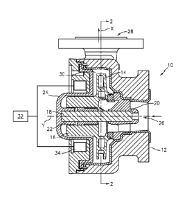
Figure 1 schematically illustrates a centrifugal pump assembly 10. Although
a magnetically driven centrifugal pump assembly 10 is illustrated in the
disclosed
non-limiting embodiment it should be understood that various pumps will
benefit
from the disclosure herein.

-2-


CA 02765508 2011-12-13
WO 2010/147709 PCT/US2010/033826
The pump assembly 10 generally includes a housing 12, an impeller 14, an
inner magnet assembly 16, a shaft 18, shaft supports 20, 22, and a containment
shell
24. A flow inlet 26 defines an axis Y and is formed by an annulus about the
shaft 18
and the front shaft support 20 (Figure 2) about which the impeller 14 rotates.
A flow
outlet 28 defines an axis X transverse to the axis Y and is formed as a
tangential
passage to a collector 30 formed within the housing 12 which contains the
impeller
14 such that the flow outlet 28 is in communication with the impeller 14.
In operation, a motor 32 powers an outer magnet assembly 34 to thereby
cause rotation of the impeller 14 within housing 12 due to a magnetic response
of
the inner magnet assembly 16. Magnetically driven centrifugal pumps are well
suited for pumping, for example, corrosive type fluids because the pump
assembly
minimizes seal requirements.
Referring to Figure 2, the flow outlet 28 includes a nozzle 40. Although the
nozzle 40 is illustrated as a separate component in the disclosed, non-
limiting
embodiment, it should be understood that the nozzle 40 may alternatively be
integrally machined and/or formed in the flow outlet 28. The nozzle 40 forms
an
interior shape which advantageously provides a rising Head vs. Flow curve to
shut-
off as compared to a current art flow outlet F (related art; Figure 3)
Referring to Figure 4A, the nozzle 40, in one non-limiting embodiment, may
be a nozzle 40A which generally includes a pocket section 42A, a throat
section
44A, a transition section 46A and a diffuser section 48A along axis X.
Referring to Figure 4B, the pocket section 42A generally defines a diameter
Dp, the throat section 44A generally defines a diameter Dth, the transition
section
46A generally defines a diameter Dt and the diffuser section 48A generally
defines
discharge diameter Dd.
The pocket section 42A may be formed within the flow outlet 28 upstream of
the throat section 44A. The pocket section, in one non-limiting embodiment may
be
a portion of the housing 12 which receives the separate nozzle 40A. That is,
the
nozzle 40A is manufactured separately from the housing 12.
The nozzle 40A defines a discharge 50A at a downstream end of the nozzle
40. The throat section 44A is generally cylindrical and is of a diameter less
than the
pocket section 42A. The throat section 44A is in communication with the
transition
-3-


CA 02765508 2011-12-13
WO 2010/147709 PCT/US2010/033826
section 46A. The transition section 46A may be a relatively short, frusto-
conical
shape in communication with the diffuser section 48A. The diffuser section 48A
may be a relatively long frusto-conical shape.
The nozzle 40 configuration allows for pressure recovery at the discharge
50A as long as flow is established. But at low or zero flow there is little,
if any,
pressure recovery which may otherwise result in the type of droopy head v.
flow
curve of conventional related art designs (Figure 3) as represented by the
Total
Dynamic Head (TDH)/Flow curves. By displacing the throat section 44A back into
the flow outlet 28 discharge passage away from the impeller 14, coupled with
the
diffuser section 48A, an advantageous rising curve to shut-off is facilitated.
Referring to Figure 5A, another non-limiting embodiment of the nozzle 40
may be a nozzle 40B that generally defines a pocket section 42B, a throat
section
44B, a transition section 46B, and a diffuser section 48B along axis X. The
transition section 46B is generally stepped out to diameter Dt from the throat
section
44B diameter Dth (Figure 5B).
Referring to Figure 6, nozzle 40A provides a Total Dynamic Head
(TDH)/Flow curve (A) that is stable and rising to shut-off but tends to
flatten off a
bit at a lower TDH value compared to nozzle 40B (curve (B)). The diameter and
length of the throat sections 44 change the (TDH)/Flow curve shape but the
curve
remains stable.
The pocket section 42 defines a pocket height Lp defined by angle a
between the pump axis of rotation Y and the intersection between the pocket
section
42 and the throat section 44 along axis X (Figure 7A). In general, the pocket
section
42 stabilizes the curve shape at shut-off. In one non-limiting embodiment, the
pocket section diameter Dp is less than or equal to the Volute Width Vw
(Figure
7B).
The throat section diameter Dth generally controls the desired operating
curve such that a reduction in the throat section 44 diameter results in a
steeper
curve (C). In one embodiment, the throat section diameter Dth is less than Dp.
The shape of the transition section 46 also affects the curve shape. For
example, a stepped transition section 46 (Figure 5A) increases the shut-off
head and
steepens the curve shape (see curve B) while an angled (gradual) transition
section
-4-


CA 02765508 2011-12-13
WO 2010/147709 PCT/US2010/033826
46 (Figure 4) generally reduces the shut-off head and flattens the curve but
remains
stable. In one embodiment, the transition section 46 diameter: Dt z (1.6 to
2.1)Dth.
A transition section length Lt z 0.55Ld - Lth.
Where:
Ld is diffuser section length.
Lth is throat section length.
A reduction in the impeller diameter, also called trimming, retains the curve
shape at lower TDH values (see curve C' and curve B'). The performance
characteristic may thus be maintained for various impeller diameters.
Elimination of the transition section (Lt = 0; Figure 8) results in a reduced
shut-off with a relatively flatter shape that delivers more flow. Drop-off
occurs at
higher flow rates (see curve D). The throat section length Lth is affected by
the
requirement to maintain an appropriate diffuser section length Ld and a
diffuser
section angle Od of approximately 5-7 degrees to match the discharge diameter
Dd.
The diffuser section 48 generally converts velocity head into pressure. The
typical diffuser section 48 defines an included angle of 20d. For a nozzle 40
with a
transition section 46 (Figures 4 and 5), the included angle would be
approximately
10 to 11 degrees. For a nozzle 40C without a transition section 46 (Figure 8),
the
included angle could be up to approximately 14 degrees.
It should be understood that like reference numerals identify corresponding
or similar elements throughout the several drawings. It should also be
understood
that although a particular component arrangement is disclosed in the
illustrated
embodiment, other arrangements will benefit herefrom.
Although particular step sequences are shown, described, and claimed, it
should be understood that steps may be performed in any order, separated or
combined unless otherwise indicated and will still benefit from the present
disclosure.
The foregoing description is exemplary rather than defined by the limitations
within. Various non-limiting embodiments are disclosed herein, however, one of
ordinary skill in the art would recognize that various modifications and
variations in
light of the above teachings will fall within the scope of the appended
claims. It is
therefore to be understood that within the scope of the appended claims, the
-5-


CA 02765508 2011-12-13
WO 2010/147709 PCT/US2010/033826
disclosure may be practiced other than as specifically described. For that
reason the
appended claims should be studied to determine true scope and content.

-6-

Representative Drawing
A single figure which represents the drawing illustrating the invention.
Administrative Status

For a clearer understanding of the status of the application/patent presented on this page, the site Disclaimer , as well as the definitions for Patent , Administrative Status , Maintenance Fee  and Payment History  should be consulted.

Administrative Status

Title Date
Forecasted Issue Date 2014-09-09
(86) PCT Filing Date 2010-05-06
(87) PCT Publication Date 2010-12-23
(85) National Entry 2011-12-13
Examination Requested 2011-12-13
(45) Issued 2014-09-09

Abandonment History

There is no abandonment history.

Maintenance Fee

Last Payment of $347.00 was received on 2024-04-26


 Upcoming maintenance fee amounts

Description Date Amount
Next Payment if standard fee 2025-05-06 $624.00
Next Payment if small entity fee 2025-05-06 $253.00

Note : If the full payment has not been received on or before the date indicated, a further fee may be required which may be one of the following

  • the reinstatement fee;
  • the late payment fee; or
  • additional fee to reverse deemed expiry.

Patent fees are adjusted on the 1st of January every year. The amounts above are the current amounts if received by December 31 of the current year.
Please refer to the CIPO Patent Fees web page to see all current fee amounts.

Payment History

Fee Type Anniversary Year Due Date Amount Paid Paid Date
Request for Examination $800.00 2011-12-13
Application Fee $400.00 2011-12-13
Maintenance Fee - Application - New Act 2 2012-05-07 $100.00 2011-12-13
Maintenance Fee - Application - New Act 3 2013-05-06 $100.00 2013-04-22
Maintenance Fee - Application - New Act 4 2014-05-06 $100.00 2014-04-22
Final Fee $300.00 2014-06-11
Maintenance Fee - Patent - New Act 5 2015-05-06 $200.00 2015-04-15
Maintenance Fee - Patent - New Act 6 2016-05-06 $200.00 2016-03-14
Registration of a document - section 124 $100.00 2017-03-29
Maintenance Fee - Patent - New Act 7 2017-05-08 $200.00 2017-05-01
Maintenance Fee - Patent - New Act 8 2018-05-07 $200.00 2018-04-26
Maintenance Fee - Patent - New Act 9 2019-05-06 $200.00 2019-05-06
Maintenance Fee - Patent - New Act 10 2020-05-06 $250.00 2020-04-20
Maintenance Fee - Patent - New Act 11 2021-05-06 $255.00 2021-04-28
Maintenance Fee - Patent - New Act 12 2022-05-06 $254.49 2022-04-29
Maintenance Fee - Patent - New Act 13 2023-05-08 $263.14 2023-04-28
Maintenance Fee - Patent - New Act 14 2024-05-06 $347.00 2024-04-26
Owners on Record

Note: Records showing the ownership history in alphabetical order.

Current Owners on Record
SUNDYNE, LLC
Past Owners on Record
SUNDYNE CORPORATION
Past Owners that do not appear in the "Owners on Record" listing will appear in other documentation within the application.
Documents

To view selected files, please enter reCAPTCHA code :


To view images, click a link in the Document Description column. To download the documents, select one or more checkboxes in the first column and then click the "Download Selected in PDF format (Zip Archive)" or the "Download Selected as Single PDF" button.

List of published and non-published patent-specific documents on the CPD .

If you have any difficulty accessing content, you can call the Client Service Centre at 1-866-997-1936 or send them an e-mail at CIPO Client Service Centre.


Document
Description 
Date
(yyyy-mm-dd) 
Number of pages   Size of Image (KB) 
Abstract 2011-12-13 2 66
Claims 2011-12-13 2 61
Drawings 2011-12-13 6 126
Description 2011-12-13 6 239
Representative Drawing 2011-12-13 1 22
Cover Page 2012-02-24 1 39
Claims 2014-01-09 4 121
Representative Drawing 2014-08-19 1 12
Cover Page 2014-08-19 1 39
PCT 2011-12-13 10 331
Assignment 2011-12-13 5 171
Maintenance Fee Payment 2019-05-06 1 33
Prosecution-Amendment 2013-07-12 2 54
Prosecution-Amendment 2014-01-09 6 206
Correspondence 2014-06-11 2 67