Note: Descriptions are shown in the official language in which they were submitted.
CA 02765680 2014-02-20
WO 2010/151510
PCT/US2010/039358
TITLE OF THE INVENTION
SEALING DEVICE AND DELIVERY SYSTEM
10 BACKGROUND OF THE INVENTION
Field of the Invention
The invention relates to a sealing device for repair of cardiac and
vascular defects or tissue opening such as a patent foramen ovale (PF0) or
shunt
in the heart, the vascular system, etc. and particularly provides an occluder
device and trans-catheter occluder delivery system.
Discussion of the Related Art
Sealing devices may be utilized for the occlusion of many types of tissue
openings, such as septal defects, PFO, and the like.
Tissue openings have traditionally been corrected by open heart surgery.
In order to avoid the trauma and complications associated with open-heart
surgery, a variety of trans-catheter closure techniques have been implemented.
In such techniques, an occluding device is delivered through a catheter to the
site of the opening or defect. A device is placed into the defect and
permanently
deployed.
A variety of trans-catheter delivered devices are known. These include
devices that require assembly at the site of the tissue opening or require
threading or "buttoning" of the discrete device elements. Other devices
include
self-expanding devices. These self-expanding devices tend to be difficult to
visualize, cumbersome to load, difficult to position at the site of a tissue
opening, and reposition. Most self-expanding devices do not conform to heart
anatomy leading to tissue erosion.
An example of a self-expanding device includes an occlusion bag, a third
tube, a guide catheter, a super elastic wire, a release mechanism and a
delivery
sheath. The super elastic wire is attached to the release mechanism and the
wire,
release mechanism, occlusion bag, guide catheter and third tube are inserted
into
1
CA 02765680 2011-12-15
WO 2010/151510
PCT/US2010/039358
a delivery sheath for transport to the aperture. After delivery, the occlusion
bag
is placed within the aperture and the wire is deployed within the bag. The bag
and wire are repositioned if necessary, and the release mechanism is activated
to
release the wire,
Another example of a self-expanding device includes a shape set tubular
metal fabric device and optionally, an occluding fiber included in the hollow
portions of the device. The metal fabric defines a medical device shaped like
a
bell, which can be collapsed for passage through a catheter for deployment in
a
channel of a patient's body.
While these and other self-expanding devices are designed for trans-
catheter delivery, they require assembly either prior to use or during use.
They
are also difficult to reposition or retrieve once deployed and provide poor
conformity to heart anatomy. For these reasons, it would be desirable to
provide
an improved sealing device for use in trans-catheter techniques. Such sealing
devices would preferably have improved conformity to heart anatomy and be
easily deployed, repositioned, and retrieved at the opening site.
Trans-catheter self-expanding sealing devices may be delivered and
deployed by a variety of means, Most trans-catheter delivery devices choose
one of two basic systems for deploying the device: pulling back an outer
catheter to release the device or pushing the device free of the catheter with
a
push rod. Each of these systems utilizes a handle to actuate the mechanism
used
to deploy the device. An example of such a system includes a flexible urging
member for urging the sealing device through a catheter and a remotely located
control means for advancing the urging member. In this example, the control
means includes a threaded, tubular shaft connected to the urging member and a
manually rotatable threaded rotor mounted on the shaft. The threads on the
rotor
mate with the threads on the shaft so that the rotation of the rotor through a
known angle will advance the shaft and the urging member a known distance.
An example of a system that utilizes a pull back outer shaft or catheter
includes a handle that may selectively hold the delivery system components at
any configuration during deployment and positioning of the device. The outer
catheter of such a system would be pulled back to release the device by
actuating a sliding lever and a rotating finger ring on the delivery system
handle.
While these and other device delivery systems are designed for trans-
catheter device deployment, they require the use of a threaded rotor, which
can
become difficult to rotate or they require large forces to pull back the outer
catheter to expose the entire length of the constrained device. Most
deployment
2
CA 02765680 2011-12-15
WO 2010/151510
PCT/US2010/039358
systems are either not reversible or very difficult to reverse once the
deployment
procedure has taken place. For these reasons, it would be desirable to provide
an improved delivery system for a sealing device. Such delivery system would
preferably have a handle able to be operated simply with a single hand and
would be able to execute multiple manipulations with minimal force or hand
movement.
SUMMARY OF THE INVENTION
A first embodiment provides a sealing device having an expandable
frame formed from a plurality of wires extending from a proximal end to a
distal
end of the frame with the wires forming a proximal and distal eyelet with a
sealing member at least partially encapsulating the expandable wire frame.
A further embodiment provides a handle for deploying a sealing device
having a housing having a slot and a length with a linear actuator located
within
the slot and the linear actuator capable of independently advancing and
retracting at least three separate components by advancing and retracting the
actuator along the slot length.
An additional embodiment provides an apparatus comprising a handle
having a housing having a slot with a length and a linear actuator located
within
the slot the linear actuator capable of independently advancing and retracting
at
least three separate components by advancing and retracting the actuator along
the slot length. The apparatus also comprising a sealing device having an
expandable frame formed from a plurality of wires extending from a proximal
end to a distal end of the frame with the wires forming a proximal and distal
eyelet with a sealing member at least partially encapsulating the expandable
wire frame.
Additional features and advantages of the invention will be set forth in
the description or may be learned by practice of the invention. These features
and other advantages of the invention will be realized and attained by the
structure particularly pointed out in the written description and claims
hereof as
well as the appended drawings.
It is to be understood that both the foregoing general description and the
following detailed description are exemplary and explanatory and are intended
to provide further explanation of the invention as claimed.
3
CA 02765680 2011-12-15
WO 2010/151510
PCT/US2010/039358
BRIEF DESCRIPTION OF THE DRAWINGS
The accompanying drawings are included to provide a further
understanding of the invention and are incorporated in and constitute a part
of
this specification, illustrate embodiments of the invention, and together with
the
description serve to explain the principles of the invention.
In the drawings:
FIG. 1 is a perspective view of a deployed sealing device attached to the
distal end of a delivery system.
FIG. 2A is a view of an expanded frame of a sealing device.
FIG. 2B is an end on view of an eyelet of a sealing device.
FIG. 2C is a end on view of a frame of a sealing device.
FIGS. 3A-B are views of components of a winding jig.
FIG. 4A is a side view of a winding jig.
FIG. 4B is a top view of a winding jig.
FIG. 5A is a side view of an expanded covered sealing device.
FIG. 5B is a side view of an expanded partially covered sealing device.
FIG. 6 is a side view of a self-centering embodiment of a sealing device.
FIG. 7 is a side view of a deployed sealing device.
FIG. 8 is a perspective view of a delivery system including a deploynent
handle and attached sealing device.
FIG. 9A-D are flow charts describing the operation of the delivery
system.
FIG. 10 is a perspective view of a sealing device deployment handle.
FIG. 11 is a perspective view of an assembly of a sealing device
deployment handle.
FIG. 12A is a top down view of an embodiment of a first linear actuator.
FIG. 12B is a side view of an embodiment of a first linear actuator.
FIG. 12C is a side view of an embodiment of a first linear actuator.
FIG. 12D is a side view of an embodiment of a first linear actuator.
FIG. 13A is a perspective view of an embodiment of a lock release
actuator.
FIG. 13B is a perspective view of an embodiment of a lock release
actuator in the activated position.
FIG. 14A is a perspective view of an embodiment of a spring.
FIG. 14B is an end on view of an embodiment of a first linear actuator.
4
CA 02765680 2011-12-15
WO 2010/151510
PCT/US2010/039358
FIG. 15 is an end on view of an embodiment of a first linear actuator
with molded spring component.
FIG. 16 is a perspective view of a spring component.
DETAILED DESCRIPTION OF THE ILLUSTRATED EMBODIMENTS
A first embodiment provides a sealing device having an expandable
frame formed from a plurality of wires extending from a proximal end to a
distal
end of the frame with the wires forming a proximal and distal eyelet with a
sealing member at least partially encapsulating the expandable wire frame.
Figure 1 shows one embodiment of sealing device 100. Sealing device
100 will be discussed in detail in a later section. Sealing device 100 may
housed
within third tube 104. Third tube 104 contains sealing device 100, first tube
102, second tube 108, retrieval cord 110 and locIdng loop 111. Third tube 104
may be manufactured of Pebaxt or any other material with suitable
biocompatible and mechanical properties. A material choice with radiopacity
may also be an option. The third tube 104 may be manufactured with or without
a reinforcing braid to provide appropriate kink resistance and strength for
the
chosen application. Third tube 104 may also be designed with or without a
radiopaque marker band. The design and materials of third tube 104 may be
chosen for other properties such as torqueability, steerability and vascular
trauma reduction. One of skill in the art can readily appreciate that there
are a
wide variety of potential materials that may be used to facilitate the present
invention. The third tube 104 may be of any size but is preferably 10fr. with
an
irmer diameter of about 0.048 mm and an outer diameter of about 0.33 mm.
Third tube 104 may be used with or without a guidewire and may include a
rapid exchange port 103. The tip of first tube 104 is preferably curved to aid
in
navigation and delivery of sealing device 100 from the access site to the
defect
with or without a guidewire.
Also shown in Figure 1 is first tube 102. As previously stated, first tube
102 may be housed within third tube 104. The first tube 102 may be of any
outer diameter size but is preferably sized to fit within the lumen of the
third
tube 104. First tube 102 may be manufactured of Pebax114 or any other material
with suitable biocompatible and mechanical properties. First tube 102 is
preferably a triple lumen catheter. The lumens may be of any geometric shape
but are preferably round or oval or a combination of both. First tube 102 may
be used to position and aid in the deployment of sealing device 100. First
tube
5
CA 02765680 2011-12-15
WO 2010/151510
PCT/US2010/039358
102 may be utilized in conjunction with second tube 108 to cause sealing
device
100 to protrude from the distal tip of third tube 104 once sealing device 100
has
reached the defect site. The first tube 102 may also have the function of
retaining sealing device 100 onto the delivery system until final device
deployment. First tube 102 has an opening 109 in the distal most end to allow
the locking loop 111 to protrude during device deployment. The opening 109
and protruding locking loop 111 provide attachment to the device delivery
system. Locking loop 111 is shown in its extended position prior to retaining
its
pre-set shape. The first tube 102 may be surface treated or coated to enhance
the
material's biocompatibility or alter or enhance the surface friction.
First tube 102 may house the second tube 108. The second tube 108 is
essentially tubular with an oval cross section and can have an outer diameter
suitable to fit inside first tube 102. A preferred outer diameter range would
be
from about 1.27 x 0.68 mm and would be flared at the distal end. The second
tube 108 may be fabricated from any suitable biocompatible material including
polymers or metals. A preferable material would be PEEK
(polyetheretherketone). Second tube 108 can be used to aid in the delivery and
deployment of sealing device 100 to a defect site. Second tube 108 is threaded
through the eyelets of sealing device 100 to hold sealing device 100 on the
delivery system and to provide stability while deploying the sealing device
100.
Sealing device eyelets will be discussed further.
Retrieval cord 110 is looped through two of the smaller lumens of the
first tube 102 and through the proximal eyelet of the sealing device 100 to
provide attachment to the delivery system and a method of retrieval once the
sealing device has been deployed. Retrieval cord 110 extends through the
length of first tube 102 with the ends terminating at the handle used for
deploying sealing device 100. Retrieval cord 110 may be manufactured of any
biocompatible material of sufficient strength and size. A preferable material
is
ePTFE (expanded polytetrafluoroethylene).
As shown in Figure 2A sealing device 100 is formed of a wire frame
200. When situated for delivery, wire frame 200 is at an extended position on
second tube 108 and within third tube 104. Wire frame 200 may be of any size
appropriate for an application but is preferably sized with finished outer
diameters of 15, 20, 25, or 30 mm. The wire frame 200 is formed of continuous
wires. Any number of wires may be used to construct the wire frame 200. A
preferable number of wires is five. The wire frame 200 can be constructed of
wires that have elastic properties that allow for wire frame 200 to be
collapsed
6
CA 02765680 2011-12-15
WO 2010/151510
PCT/US2010/039358
for catheter based delivery or thoracoscopic delivery, and self-expand to a
"memory" induced configuration once positioned in a defect. The elastic wire
may be a spring wire, or a shape memory NiTi (nitinol) alloy wire or a super-
elastic NiTi alloy wire. The elastic wire may also be of a drawn-filled type
of
NiTi containing a different metal at the core. Preferably, wire frame 200
would
be constructed of a drawn-filled type of NiTi wire containing a radiopaque
metal
at the center. Upon deployment, the wire structure resumes its deployed shape
without permanent deformation.
Wire frame 200 and other wire frames shown are formed from elastic
wire materials that have outer diameters between 0.12 and 0.4 mm. In a
preferable embodiment, wire outer diameter size would be about 0.3 nun. When
formed, wire frame 200 comprises a distal bumper 208, distal eyelet 204,
locking loop 206, an optional center eyelet 203, and proximal eyelet 202.
Figure
2B shows the position of elastic wires during the formation of eyelets 202,
203
and 204 of wire frame 200.
Figure 2C shows a disk formed when wire frame 200 is deployed. The
elastic wires that forin wire frame 200 form petals 212 during deployment. The
pre-set elastic wire configuration of wire frame 200 allows the frame to twist
during deployment. This twist forms petals 212. Deployed petals 212 form the
outer diameter 214 of the wire frame 200. Deployed petals 212, when covered
with sealing member 106, form proximal and distal disks, to be discussed
further. Petals 212 are optimally formed to have overlapping zones 216 to
improve sealing qualities. The radius of petals 212 may be maximized to
minimize sharp bend angles in the elastic wire and to minimize unsupported
sections of petals 212 that improve sealing qualities of the device, reduce
bending fatigue in the wire and aid in reducing device loading forces.
Deployed
petals 212 form a disk on either side of the center eyelet 203. The deployed
configuration will be discussed further.
Construction of wire frame 200 may be accomplished by a variety of
means including machine winding with automatic wire tensioning or by hand
winding with weights suspended from each wire during construction. Shown in
Figures 3A-C are keyed center pin 300 and button 304, which may be used to
aid in the construction of wire frame 200. One commonly skilled in the art
would recognize that there are many materials suitable for use as a
manufacturing aid or tooling. A preferable material for use in forming a
center
pin 300 would be cobalt high strength steel. A preferable material for use in
forming a button 304 and winding jig would be corrosion resistant tool steel.
7
CA 02765680 2011-12-15
WO 2010/151510
PCT/US2010/039358
The winding jig will be discussed further. Shown in detail in Figure 3A, keyed
center pin 300 may have groove 302, which can be used to secure an elastic
wire
during device construction. Keyed center pin 300 can be used to guide an
elastic wire through opening 306 in button 304, the features of which are
illustrated in Figures 3B-C. Button 304 is preferably formed with an indention
308 in the bottom to fit securely in a winding jig. An elastic wire held in
groove
302 and inserted through opening 306 in button 304 can form a bumper 208 and
locking loop 206. Keyed center pin 300 is also used in the formation of
eyelets
202, 203 and 204. During device construction, after the fonnation of bumper
208, elastic wires can be wound around keyed center pin 300 to form a distal
eyelet 202. Other eyelets, 203 and 204 can be formed in a similar manner.
Once keyed center pin 300 is inserted in button 304 an elastic wire may be
inserted into grooves in a winding jig.
A winding jig may be used to secure and form the elastic wires during
construction and processing of the sealing device 100. A typical winding jig
may be constructed as commonly known in the arts. Materials used for
construction of such a winding jig have been discussed previously. A
preferable
winding jig is shown in Figures 4A and 4B. Figure 4A illustrates a side view
of
the winding jig 400. Figure 4B shows a view of the top of a preferable winding
jig 400. Winding jig 400 contains an aperture 402 that may be shaped and sized
to hold keyed center pin 300 and button 304 during device construction.
Grooves 404 in the jig surface are used to secure and form the elastic wires
into
petals 212. Grooves 404 may be of any diameter but are preferably sized to
accommodate an outer diameter of elastic wire. In one embodiment shown in
Figure 5A, the winding jig assembly may be used to form a center eyelet 203, a
petal assembly and proximal eyelet 204. The shaped wire may be constrained in
the winding jig assembly, heated and processed to shape set as commonly
known in the arts.
Figure 5A shows an embodiment of sealing device 100 which is a
composite assembly of wire frame 200 and sealing member 106. Sealing
member 106 may be attached to wire frame 200 by a bonding agent. Wire frame
200 may be coated with a bonding agent, for example fluorinated ethylene
propylene (FEP) or other suitable adhesive. The adhesive may be applied
through contact coating, powder coating, dip coating, spray coating, or any
other
appropriate means. In a preferred embodiment, the FEP adhesive is applied by
electrostatic powder coating. Sealing member 106 may be constructed of a
variety of materials, such as DACRON , polyester, polyethylene,
8
CA 02765680 2011-12-15
WO 2010/151510
PCT/US2010/039358
polypropylene, fiuoropolymers, polyurethane, foamed films, silicone, nylon,
silk, thin sheets of super-elastic materials, woven materials, polyethylene
terephthalate (PET), collagen, pericardium tissue or any other biocompatible
material. In one embodiment, sealing member 106 can be formed of a thin
porous ePTFE (expanded polytetrafluoroethylene) substrate. Sealing member
106 is designed to enhance the defect closure characteristics of sealing
device
100 by providing defect blockage and a medium for cellular in growth.
Also shown in Figure 5A are proximal, distal and center eyelets (202,
203 and 204) respectively covered with sealing member 106 and wrapped with a
film. The eyelets 202, 203 and 204 may be wrapped with a film to encourage
adhesion of sealing member 106 to the device. The film used to wrap eyelets
202, 203, and 204 may be any biocompatible thin material but is a material
preferably comprised of multiple layers of thin porous ePTFE that may be
laminated with one or more layers of non-porous FEP.
Figure 5B illustrates an embodiment of sealing device 100 that includes
a sealing member 508 that partially covers wire frame 200. A partially covered
device may have either the distal or proximal bulb covered in part or in
entirely
with a sealing member 508.
Another embodiment of the device is a self centering device 600. Shown
in Figure 6, self centering device 600 comprises a wire frame 602 similar to
that
of wire frame 200. Self centering device 600 is a composite assembly of wire
frame 602 and sealing member 604. Wire frame 602 may be constructed with
the same techniques and a material as wire frame 200 but has no center eyelet.
Wire frame 602 comprises distal bumper 606, covered distal eyelet 608, covered
proximal eyelet 610, and locking loop 612. The pre-set elastic wire
configuration of wire frame 602 allows the frame to twist upon deployment and
create a centering region 614 of the device 600 during deployment. During
deployment, region 614 may center itself in the defect forming a disk
comprised
of petals on either side of region 614 and the defect.
Figure 7 shows a sealing device 100 fully deployed. During deployment,
the constraint of the third tube 104 is removed from device 100 and the device
returns to its pre-set shape. During deployment and locking, lock loop 111 is
released from the constraint of first tube 102 and returns to its pre-set
shape,
curling from the proximal eyelet 202. In this manner, the device is locked in
a
deployed state. Figure 7 also illustrates the position of the proximal and
distal
disks, elements 702 and 704, in relation to the proximal, center, and distal
eyelets 202, 203, and 204 respectively.
9
CA 02765680 2011-12-15
WO 2010/151510
PCT/US2010/039358
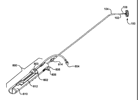
Figure 8 shows a perspective view of sealing device 100 attached to a
delivery system including first tube102, third tube 104, and a handle for
deploying a sealing device 100. Figure 8 further illustrates a fist linear
actuator
802, a flushing port 804, the second linear actuator 806, lock release
actuator
808, a housing 810 and a slot with a length in the housing 812. First linear
actuator 802 may have a variety of configurations which will be discussed
further.
Figures 9A-D are flow charts which describe the movements of the
various components of the delivery system and attached sealing device 100
during use. Loading sealing device 100 into the delivery system prior to use
is
described in Figure 9A. Components of the delivery system handle are shown in
Figures 8, 10 and 11. A clinician may flush the delivery system by attaching a
syringe or other suitable implement onto flushing port 804 and filling the
system
with saline or any other appropriate flushing material. The first linear
actuator
802 may then be moved in slot 812 in housing 810 against a spring 1100.
Spring 1100 may be configured as shown or may be formed as a leaf spring,
stepped spring or any form commonly known in the arts. This action rotates the
mandrel control lever 1000, shown in Figure 11, about a slider rod 1102 to the
side of housing 810. This same motion moves the first linear actuator 802 free
of distal notch 1104 in the sizing insert 1103 and prevents the second tube
108
from translating either proximally or distally. Sizing insert 1103 may be of
any
material with suitable mechanical properties.
Typical handles, handle components, tools or catheters used to deliver
medical devices can comprise commonly known materials such as Amorphous
Commodity Thermoplastics that include Polymethyl Methacrylate (PMMA or
Acrylic), Polystyrene (PS), Acrylonitrile Butadiene Styrene (ABS), Polyvinyl
Chloride (PVC), Modified Polyethylene Terephthalate Glycol (PETG),
Cellulose Acetate Butyrate (CAB); Semi-Crystalline Commodity Plastics that
include Polyethylene (PE), High Density Polyethylene (HDPE), Low Density
Polyethylene (LDPE or LLDPE), Polypropylene (PP), Polymethylpentene
(PMP); Amorphous Engineering Thermoplastics that include Polycarbonate
(PC), Polyphenylene Oxide (PPO), Modified Polyphenylene Oxide (Mod PPO),
Polyphenelyne Ether (PPE), Modified Polyphenelyne Ether (Mod
PPE),Thermoplastic Polyurethane (TPU); Semi-Crystalline Engineering
Thermoplastics that include Polyarnide (PA or Nylon), Polyoxyrnethylene
(POM or Acetal), Polyethylene Terephthalate (PET, Thermoplastic Polyester),
Polybutylene Terephthalate (PBT, Thermoplastic Polyester), Ultra High
CA 02765680 2011-12-15
WO 2010/151510
PCT/US2010/039358
Molecular Weight Polyethylene (UILMW-PE); High Performance
Thermoplastics that include Polyimide (PI, Imidized Plastic), Polyamide Imide
(PAI, Imidized Plastic), Polybenzimidazole (PBI, Imidized Plastic); Amorphous
High Performance Thermoplastics that include Polysulfone (PSU),
Polyetherimide (PEI), Polyether Sulfone (PES), Polyaryl Sulfone (PAS); Semi-
Crystalline High Performance Thermoplastics that include Polyphenylene
Sulfide (PPS), Polyetheretherketone (PEEK); and Semi-Crystalline High
Perfonnance Thermoplastics, Fluoropolymers that include Fluorinated Ethylene
Propylene (FEP), Ethylene Chlorotrifluroethylene (ECTFE), Ethylene, Ethylene
Tetrafiuoroethylene (ETFE), Polychlortrifiuoroethylene (PCTFE),
Polytetrafluoroethylene (PTFE), Polyvinylidene Fluoride (PVDF),
Perfluoroalkoxy (PFA). Other coinmonly known medical grade materials
include elastomeric organosilicon polymers, polyether block amide or
thermoplastic copolyether (PEBAX) and metals such as stainless steel and
nickelltitanium alloys.
A distal notch 1104 and proximal notch 1106 in sizing insert 1103 may
be used to aid in the positioning of the first linear actuator 802 in housing
slot
812. The distance between the two notches, 1104 and 1106 respectively, may be
the length of sealing device100 when it is elongated over second tube 108
prior
to loading onto the delivery system. Sizing insert 1103 may be sized to
accommodate a variety of device lengths and is preferably from about 22.28 cm
long with a distance between the proximal end of distal notch 1104 and
proximal end of proximal notch 1106 from about 6.25-13.32 cm. Notches 1104
and 1106 may be of any shape but are preferably rectangular.
The first linear actuator 802 is then moved to a mid point in slot 812
toward the proximal end of the housing 810. This action causes the first tube
102 to move proximally and the sealing device 100 proximal end to move
proximally, thus elongating sealing device 100. First linear actuator 802 may
be
any shape (lever, ball) but is preferably shaped to accorrunodate a
clinician's
thumb. First linear actuator 802 may be constructed of any material with
suitable mechanical properties but is preferably a material similar to that of
sizing insert 1103. A feature of the first linear actuator 802 are recessed
teeth
formed in the top portion of the first linear actuator 802 for securing
retrieval
cord 110. This feature is preferred but optional. The teeth could be made into
any tortuous path or have any shape desired to create resistance for retrieval
cord 110 during loading, deployment, or retrieval of sealing device 100.
Corresponding protruding teeth (not shown) may be formed in the bottom
11
CA 02765680 2011-12-15
WO 2010/151510
PCT/US2010/039358
surface of retrieval cord lock 803. These teeth may fit together and hold the
retrieval cord firnily. Other methods commonly known in the art for securing a
small diameter cord may also be used and will be discussed in detail in a
following section.
The first linear actuator 802 is then moved further proximally until the
device is loaded in third tube 104. During this action, spring 1100 pushes the
first linear actuator 802 and the mandrel control lever 1000 to the left of
slot 812
and into the proximal notch 1106 in sizing insert 1103. The second tube 108 is
free to move proximally with sealing device 100 and first tube 102. As the
first
linear actuator 802 is moved proximally, the second tube 108, sealing device
100 and first tube 102 slide or translate into the third tube 104. After the
first
linear actuator 802 is in its proximal most position, the system may again be
flushed with saline in the manner described above.
Alternate embodiments of first linear actuator 802 are shown in Figures
12A-D. Figure 12A shows a perspective view of the alternate linear actuator
1108 in the locked retrieval cord position. Linear actuator 1108 is similar in
construction to linear actuator 802 but features a retrieval cord locking ring
1110
and retrieval cord groove 1112. Figure 12B depicts alternate embodiment 1114,
which is configured with a thumb wheel 1116 that extends beyond the sides of
the linear actuator to facilitate easy manipulation. Thumb wheel 1116 is
screwed onto a threaded post 1118 around which the retrieval cord is wound.
Embodiment 1114 also contains a retrieval cord groove 1120 through which the
retrieval cord is guided prior to securing it around threaded post 1118,
Figure
12C illustrates yet another embodiment 1122 that utilizes a side fitted
threaded
thumb wheel 1124 around which the retrieval cord is wound and secured to the
actuator 1122 by the act of inserting the threaded post 1124 into a threaded
aperture (not shown) in the side of the actuator 1122. Prior to threading the
retrieval cord around the threaded post 1124, the retrieval cord is inserted
through the retrieval cord groove 1126. Yet another embodiment 1128 is shown
in Figure 12D. Embodiment 1128 shows a linear actuator with molded thumb
wheel 1130. The thumb wheel 1130 extends slightly beyond the edges of the
linear actuator facilitating manipulation of the linear actuator. The
retrieval cord
is inserted through cord groove 1132 and wound around a threaded post (not
shown). The molded thumb wheel 1130 is then secured on the threaded post
securing the retrieval cord.
Deploying sealing device 100 into a defect is described in Figure 9B.
The first linear actuator 802 is moved distally until a stop is reached. This
12
CA 02765680 2011-12-15
WO 2010/151510
PCT/US2010/039358
movement causes the first tube 102 and second tube 108 to move distally within
the third tube 104. The linear actuator 802 must then be moved to the right in
slot 812, against spring 1100. When the linear actuator 802 is moved to the
right, mandrel control lever 1000 rotates on slider rod 1102. This action
causes
the linear actuator 802 to be free of the proximal notch 1106 in sizing insert
1103. After this action, the linear actuator 802 is further translated
distally.
This causes the first tube 102 and proximal eyelet 202 of sealing device 100
to
move distally. Also affected by this action is the distal end of sealing
device
100 which is prevented from moving. The first tube 102 guides the device out
of the third tube 104 to deploy the device in a defect. Moving linear actuator
802 distally to the end of slot 812 results in the entire sealing device being
deployed. One skilled in the art would recognize that the steps described
above
could be halted and reversed at certain points to allow optimal positioning of
sealing device 100.
Locking the device is described in the flowchart illustrated in Figure 9C.
The retrieval cord lock 803 would be unsnapped from the first linear actuator
802. A clinician would gasp the second linear actuator 806 by gripping
attached lock release actuator 808 and press it toward the middle of housing
810.
The second linear actuator 806 may be of any size or shape but is preferably
sized to fit within a slot 1002 in the longitudinal surface of housing 810.
Linear
actuator 806 is fitted with lock release actuator 808 by means of a snap
fitting.
Any means of attachment would suffice to fasten lock release actuator 808 to
linear actuator 806 such as glue or construction as a molded part. Materials
appropriate for both the second linear actuator 806 and lock release actuator
808
may be any material of suitable mechanical properties but are preferably
similar
to that of the previously mentioned handle components. Lock release actuator
808 is designed to enable a user to grip the device securely. Gripping may be
aided by protrusions on the lateral sides of the lock release actuator 808.
These
protrusions may be made of a similar material as that of the lock release
actuator
808 or may be made of a material with a high coefficient of friction or of a
material more compliant than that of lock release actuator 808. These
protrusions may also be made with grating, a roughening, a raised design, or
striations in the surface in conjunction with the material listed above to
further
aid in the gripping of the device. These features on the surface of lock
release
actuator 808 may also be used to aid in gripping without the use of gripping
protrusions and may be applied directly to the lateral surface of the second
linear
actuator 806. Slot 1002 may be configured to have a stop to hold the second
13
CA 02765680 2011-12-15
WO 2010/151510
PCT/US2010/039358
linear actuator 806 in a distal most position until lock release of the
sealing
device. A preferred stop is shown in Figures 10 and 11 in the form of a
corrugated area but may also be any manner of mechanical stop. Slot 1002 may
be of any length but preferably has a length sufficient to translate motion
proximally about the width of the second linear actuator 806 plus about 3.18
cm.
Slot 1002 may be any shape that would accommodate the second linear actuator
806.
An alternate embodiment of second linear actuator 806 is shown in
Figures 13A and 13B. Instead of gripping lock release actuator 808 and
activating second linear actuator 806 a rotatable lock release actuator 1300
is
gipped and rotated to affect lock release. The rotatable lock release actuator
1300 may contain a window 1302 which would prevent forward movement of
the first linear actuator 802. When rotated, lock release actuator 1300 allows
the
same actions as lock release actuator 806 shown in Figure 10.
Once the second linear actuator 808 is gripped, a clinician may move the
second linear actuator 806 proximally. This action results in proximal
movement of third tube 104, mandrel control lever 1000, sizing insert 1103 and
second tube 108. Second tube 108 moves proximally from between eyelets of
the device. An alternate method of achieving this action would be to provide a
twist mechanism to the distal end of the handle instead of a second linear
actuator 806. This twist mechanism would be provided with a slot that allows
for the same movement of the third tube 104, mandrel control lever 1000,
sizing
insert 1103 nad second tube 108 as the second linear actuator 806.
Once lock release has been achieved, the retrieval cord lock 803 is then
twisted to remove it from the first linear actuator 802 and pulled until the
retrieval cord 110 is free of the delivery system. Retrieval cord 110 is
attached
to the retrieval cord lock 803 at one end. Retrieval cord 110 may be
constructed
of any material with suitable mechanical properties such as Kevlan.ID,
flexible
metal wire, polymers and the like. A preferably material for retrieval cord
110
is an ePTFE fiber. Retrieval cord lock 803 may be configured in a variety of
shapes and sizes. Possible retrieval cord locks may be designed to provide a
slot
in the linear actuator 802 through which the retrieval passes. In one
configuration, the retrieval cord is secured by passing the cord through a
slot or
hole in the axis of the thumb wheel disposed in the linear actuator 802 and
tightened by twisting the thumb wheel. An alternate configuration would
provide a slide lock that binds the retrieval cord between the lock and the
linear
14
CA 02765680 2011-12-15
WO 2010/151510
PCT/US2010/039358
actuator 802 using friction. A preferred design would be to secure the
retrieval
cord between teeth formed in the retrieval cord lock as shown in Figure 11.
Materials suitable for constructing retrieval cord lock 803 are similar to
that used to construct housing 810 and other handle components. As mentioned
previously, retrieval cord lock 803 preferably has teeth or protrusions that
correspond to indentations in linear actuator 802 for the purpose of gripping
retrieval cord 110. Retrieval cord lock 803 may be configured in a variety of
shapes to enable retrieval cord 110 to be secured. A preferred configuration
would include apertures through the retrieval cord lock 803 to allow retrieval
cord 110 to be threaded therethrough and knotted. After twisting the retrieval
cord lock 803, it is pulled until the retrieval cord 110 is removed from the
delivery system.
Prior to the step four described in Figure 9C, the sealing device 100 may
be retrieved as described in the flowchart illustrated in Figure 9D. The
retrieval
cord lock 803 may be snapped into the first linear actuator 802. This serves
to
lock the retrieval cord 110 in place. The clinician then moves the first
linear
actuator 802 to the right edge of slot 812. The first linear actuator 802
moves in
slot 812 to the right pressing on spring 1100 while the mandrel control lever
1000 rotates on the slider rod 1102 to the right of the handle. Slider rod
1102 is
preferably of a round cross-section but one skilled in the art would recognize
that a variety of cross-sectional shapes (e.g. square or triangular) would be
acceptable. Slider rod 1102 could also be configured in the shape of a crown
spring 1400 as shown in Figures 14A and B. The spring could be inserted in a
slot 1402 through the linear actuator to allow fore and aft translation of the
linear actuator. An alternate embodiment of spring 1100 may be a spring
molded as an integral part 1500 of first linear actuator 802 as illustrated by
Figure 15. Another embodiment of spring 1100 is shown in Figure 16. In this
configuration, a spring 1600 is attached to housing 810 and pushes on the
first
linear actuator 802 in key positions. As stated above, one skilled in the art
would recognize the appropriate materials for use as a spring or molded part.
The first linear actuator 802 is free of distal notch 1104 and the second tube
108
is prevented from moving. The first linear actuator is moved proximally by the
clinician causing first tube 102 to move proximally. This motion translates
the
proximal end of sealing device 100 proximally elongating the device 100 and
allowing it to be pulled into the third tube 104.
Alternately, the sealing device 100 may be retrieved in the following
manner. The retrieval cord lock 802 may be snapped into the first linear
CA 02765680 2011-12-15
WO 2010/151510
PCT/US2010/039358
actuator 802. The retrieval luer 814 may be unscrewed which separates the
delivery catheter 104 from the handle 800. Device retrieval may be
accomplished by then gasping the entire handle 800 and withdrawing it while
holding the delivery catheter 104 in place. This action will force the device
100
to be withdrawn through the delivery catheter 104.
EXAMPLES:
Without intending to limit the scope of the invention, the following
examples illustrate how various embodiments of the invention may be made
and/or used.
Example 1:
A sealing device similar to Figure 1 was manufactured using the
following components and assembly process.
An expanded polytetrafluoroethylene material was obtained with the
following properties:
Methanol bubble point of 1 psi
Mass/area of 2.2 grams/square meter
Longitudinal maxirnum load of 1.6 kg/inch
Thickness of 0.0003 inch
Longitudinal matrix tensile strength of 92000 psi
The following test methods and equipment were used to determine the
above-mentioned properties: Methanol bubble point was measured using a
custom built machine with a 1 inch diameter foot, a ramp rate of 0.2
psi/second
and a liquid media of methanol. Length and width of the material were
measured using a metal ruler. Mass/area was measured using a balance (Model
GF-400 Top Loader Balance, ANG, San Jose CA.) with a 36 x 5 inch sample.
Longitudinal maximum load was measured using a materials test machine
(Model 5564, 1nstron, Grove City, PA) equipped with a 10 kg load cell. The
gauge length was 1 inch and the cross head speed was 25mm/minute. Sample
width was 1 inch. Longitudinal tensile test measurements were taken in the
length direction of the material. Thickness was measured using a thickness
gauge (Mitutoyo Digital Indicator 547-400) with a foot diameter of 'A inch.
The
longitudinal matrix tensile strengths (MTS) were calculated using the
following
equation: Density was calculated using the formula, density = mass/volume.
16
CA 02765680 2011-12-15
WO 2010/151510
PCT/US2010/039358
Matrix Tensile Strength = samrier PTFE)
(p
where: p PTFE 2.2 gramsxc
a man* = (Maximum LoadliVidth),Thickness
___________________________________ ..(Mass..Area)iThickness
An expanded polytetrafluoroethylene with a thin layer of FEP
(fluorinated ethylene propylene) material was obtained with the following
properties:
Mass/area of 36.1 grams/square meter
Maximum Load, Longitudinal of 12.6 kg/inch
Maximum Load, Transverse of 0.3 kg/inch
Thickness of 0.0012 inch
The following test methods and equipment were used to determine the
above-mentioned properties: Material was weighed using a precision analytical
balance (Model GF400 Top Loader Balance, ANG, San Jose CA.) with a
sample area of 36 x 1 inch sample. Length and width of the material were
measured using a metal ruler. Material thickness was measured using a digital
thickness gauge (Mitutoyo Digital Indicator 547-400) with a foot diameter of
1/4
inch. Maximum transverse load was measured using a materials test machine
(Model 5564, Instron, Grove City, PA) equipped with a 10kg load cell. The
sample width was 1 inch, the gauge length was 1 inch and the cross head speed
was 25m.m/minute. Maximum longitudinal load was measured using a materials
test machine (Model 5564, Instron, Grove City, PA) equipped with a 200kg
load cell. The sample width was 1 inch, the gauge length was 1 inch and the
cross head speed was 25mrn/minute. Longitudinal tensile test measurements
were taken in the length direction of the material and transverse tensile test
measurements were taken in the direction orthogonal to the length direction.
A distal eyelet was formed by first obtaining a length of 10% platinum
drawn filled nitinol wire (Fort Wayne Metals, Fort Wayne, IN.) with a diameter
of about 0.23 mm. This wire was labeled "first wire". A free end of the first
wire was doubled on itself to create an open-ended loop and the open-ended
loop was inserted into the button. The button was then inserted onto the keyed
center pin. The button was shaped to have an opening through the center to
accommodate the keyed center pin and to have features that allow it to rest
securely in the winding jig. The keyed center pin (major axis of about 0.51
min
17
CA 02765680 2011-12-15
WO 2010/151510
PCT/US2010/039358
and minor axis of about 0.25 rnm and length of about 10.16 mm) was then
inserted in the center of a winding jig. The keyed center pin was fabricated
from
high strength steel (Super Cobalt HSS Tool Bit, MSC#56424278, Seco
Fagersta). The steel was tempered per manufacture's instructions at 1475 F for
one hour. The winding jig and button were fabricated in house from corrosion
resistant tool steel.
A second length of the same type of drawn filled nitinol wire was
obtained and labeled "fifth wire". The first, fifth and an additional three
wires
were tensioned by attaching weights to the wire ends. The first wire and the
fifth wire were then wound around the free end of the first wire one full
revolution. The three additional wires were introduced to the winding jig and
all
five wires were wound around the free end of the first wire to a height of
about
1.98 mm.
A distal disk was then formed by separating the five wires and securing
them in radial grooves around the circumferential edge of the winding jig. A
radius was formed with the dimensions of 15 mm. Each wire formed one petal
of the distal disk. The radius on the curvature of the petals was maximized in
order to minimize sharp bend angles in the wire.
A center eyelet was formed by grouping the wires together and winding
them around the free end of the first wire and the keyed center pin to a
height of
about 1.98 mm. The wires were then separated and secured in radial grooves
around the circumferential edge of the winding jib creating a proximal disk
with
a radius of 15 mm.
A proximal eyelet was formed by again grouping the five wires and
winding them around the free end of the first wire and the keyed center pin to
a
height of about 1.98 mm. The five wires were then separated and secured by
placing a stainless steel plate on top of the wires and locking down the plate
with screws. The free end of the first wire was then wound one revolution
around a stainless steel pin with a diameter of about 3.18 mm and secured
similarly to the other five wires.
The jig with sealing device was then removed from the stabilizing fixture
and placed in an oven (BlueM SPX Electric Forced Air Convection Oven) and
the wires were thermally shape set as commonly known in the arts. The device
and jig were then water quenched. The secured wires were released from the
securing plate and the device was chilled and removed from the jig and keyed
center pin. The device was then placed on a piece of flattened PEEK
(polyetherether ketone) and trimmed by hand to the outer diameter of the
distal
18
CA 02765680 2011-12-15
WO 2010/151510
PCT/US2010/039358
eyelet. The lock loop was trimmed by hand to a point just beyond one complete
revolution and pulled through the proximal and center eyelets.
The device was pushed from the PEEK mandrel onto a keyed stainless
steel process mandrel with an oval cross section. The mandrel was produced
from flattened stainless steel wire (Ft. Wayne Metals, Fort Wayne, IN) with an
oval cross-section to have a 45 clockwise twist between the proximal eyelet
and
the center eyelet and a second 45 clockwise twist between the center eyelet
and
the distal eyelet.
The process mandrel and device were then placed in a stabilizing fixture
which was placed in a FEP powder coating machine (C-30, Electrostatic
Technology, Inc., Bradford, CN) and processed until coated completely. Excess
FEP powder was removed from the device. The FEP was vacuumed from the
lock loop, process mandrel and bumper. The process mandrel and device were
removed from the stabilizing fixture, placed into an oven and baked to set the
FEP coating as commonly known in the arts.
A hollow core film mandrel (35.99 mm O.D. 76.2 cm long stainless
steel) was obtained. Expanded polytetrafluoroethylene material with a slit
width
of 22.22 mm was obtained and loaded onto a spiral wrapping machine. The
machine was manufactured in house to wrap PTFE (polytetrafluoroethylene)
material at any desired angle, tension and rate. The mandrel was loaded onto
the
wrapping inachine and the material was wrapped three times around the
circumference of the hollow core mandrel. The material was then wrapped
around the mandrel at an angle of about 8' for the length of the mandrel. The
direction of wrapping was reversed and the material over wrapped at the same
angle. The third and fourth layers were wrapped in the same manner with the
seams offset. The mandrel was removed from the wrapping machine, inserted in
an oven and baked at 370 C for 45 minutes. The wrapped mandrel was
removed from the oven and allowed to cool to room temperature. The resulting
PTFE tube was removed from the mandrel.
The PTFE tube was then cut to about 140 mm and hand stretched to a
desired length 155 mm. The PTFE tube was then pulled over the frame. The
PTFE tube was then crimped onto the center eyelet and then crimped onto the
distal and proximal eyelets.
An expanded polytetrafluoroethylene with a thin layer of FEP
(fluorinated ethylene propylene) material was then wrapped four times around
the eyelets starting with the center eyelet. The wrapped eyelets were tacked
into
place a soldering iron. The PTFE tube was then heat set for 3 minutes at 320
C
19
CA 02765680 2011-12-15
WO 2010/151510
PCT/US2010/039358
and trimrned to the outer most points of the proximal and distal eyelets. The
device was removed from the mandrel.
Example 2:
A sealing device similar to Figure 6 was manufactured using the
following components and assembly process.
Expanded polytetrafluoroethylene and expanded polytetrafluoroethylene
with a thin layer of FEP (fluorinated ethylene propylene) materials similar to
that described in Example 1 were obtained.
A distal eyelet was formed by first obtaining a length of 10% platinum
drawn filled nitinol wire (Fort Wayne Metals, Fort Wayne, IN.) with a diameter
of about 0.23 mxn. This wire was labeled "first wire". A free end of the first
wire was doubled on itself to create an open-ended loop and the open-ended
loop was inserted into the button. The button was then inserted onto the keyed
center pin. The button was shaped to have an opening through the center to
accommodate the keyed center pin and to have features that allow it to rest
securely in the winding jig. The keyed center pin (major axis of about 5.79 mm
and minor axis of about 0.25 mm and length of about 10.16 mm) was inserted in
the center of a winding jig. The keyed center pin was fabricated from high
strength steel (Super Cobalt HSS Tool Bit, MSC#56424278, Seco Fagersta).
The winding jig and button were fabricated in house from corrosion resistant
tool steel.
A second length of the same type of drawn filled nitinol wire was
obtained and labeled "fifth wire". The first, fifth and an additional three
wires
were tensioned by attaching weights to the wire ends. The first wire and the
fifth wire were then wound around the free end of the first wire one full
revolution. The three additional wires were introduced to the winding jig and
all
five wires were wound around the free end of the first wire to a height of
about
1.98 mm.
A device was then formed by separating the five wires and securing
them in radial grooves around the circumferential edge of the winding jig. A
radius was formed with the dimensions of 15 mrn. Each wire made an entire
revolution around the winding jig.
A proximal eyelet was formed by grouping the five wires and winding
them around the free end of the first wire and the keyed center pin to a
height of
about 1.981 mm. The five wires were then separated and secured by placing a
stainless steel plate on top of the wires and locking down the plate with
screws.
CA 02765680 2011-12-15
WO 2010/151510
PCT/US2010/039358
The free end of the first wire was then wound one revolution around a
stainless
steel pin with a diameter of about 3.18 mm and secured similarly to the other
five wires.
The jig with sealing device was removed from the stabilizing fixture and
placed in an oven (Blue M SPX Electric Forced Air Convection Oven) where
the wires were partially thermally shape set as commonly known in the arts.
The device and jig were then water quenched. The secured wires were released
from the securing plate and then the device was chilled and removed from the
jig and keyed center pin. The lock loop was trimmed by hand to a point just
beyond one complete revolution and pulled through the proximal and center
eyelets.
The device was pushed from the PEEK mandrel onto a keyed stainless
steel transfer mandrel with an oval cross section. The mandrel was produced
from flattened stainless steel wire (Ft. Wayne Metals, Fort Wayne, IN) with an
oval cross-section. The device was then partially removed from one end of the
transfer mandrel. The removed device end was twisted approximately 180
clockwise and repositioned on the transfer mandrel. The device and transfer
mandrel were placed in an oven (Blue M SPX Electric Forced Air Convection
Oven) where the wires were thermally shape set as commonly known in the arts.
The transfer mandrel and device were then placed in a stabilizing fixture
which was placed in a FEP powder coating machine (C-30, Electrostatic
Technology, Inc., Bradford, CN) and processed until coated completely. Excess
FEP powder was removed. FEP powder was vacuumed from the lock loop,
process mandrel and bumper. The transfer mandrel and device were then
removed from the stabilizing fixture, placed into an oven and baked to set the
FEP coating as commonly known in the arts.
A hollow core film mandrel (35.99 mm O.D. 76.2 cm long stainless
steel) was obtained. An ePTFE material with a slit width of 22.24 mm was
obtained and loaded onto a spiral wrapping machine. The machine was
manufactured in house to wrap ptfe film at any desired angle, tension and
rate.
The mandrel was loaded onto the wrapping machine and the film was wrapped
three times around the circumference of the hollow core mandrel. The ePTFE
material was then wrapped around the mandrel at an angle of about 8 for the
length of the mandrel. The direction of wrapping was reversed and the material
over wrapped at the same angle. The third and fourth layers were wrapped in
the same manner with the seams offset. The mandrel was removed from the
wrapping machine, inserted in an oven and baked at 370 C for 45 minutes. The
21
CA 02765680 2011-12-15
WO 2010/151510
PCT/US2010/039358
wrapped mandrel was removed from the oven and allowed to cool to room
temperature. The resulting ePTFE tube was removed from the tnandrel.
The ePTFE tube was then cut to about 140 mm and hand stretched to a
desired length 155 mm. The ePTFE tube was then pulled over the frame. The
ePTFE tube was then crimped onto the distal and proximal eyelets. An ePTFE
with a thin layer of FEP (fluorinated ethylene propylene) material was then
wrapped four times around the eyelets. The wrapped eyelets were tacked into
place a soldering iron. The ePTFE tube was then heat set for 3 minutes at 320
C and trimmed to the outer most points of the proximal and distal eyelets. The
device was then removed from the mandrel.
Example 3:
An handle assembly similar to Figure 8 was manufactured using the
following components and assembly process.
Cotnponents for the handle assembly were fabricated using an injection
molding process. The parts were fabricated by Contour Plastics (Baldwin, WI)
using Lustran 348. This material was suitable for use in medical devices and
has an advertised tensile strength of 48.2 MPa and a tensile modulus of 2.62
GPa. Nine parts were fabricated using this injection process and Lustrane 348.
The parts included the second linear actuator, flushing gasket retainer, a
first
linear actuator, retrieval cord lock, mandrel control lever, left body
housing,
sizing insert, right body housing, and a lock release actuator.
Other materials required for the assembly of the handle were purchased
items. A catheter tube formed with a layup process commonly known in the arts
was ordered (Teleflex Medical, Jaffrey, NH) with an 1.D. of 0.048 mm and an
O.D. of 0.33 mm and a platinum iridium marker band placed near the end of the
distal tip. The main body of the catheter tube was Pebax 7233 tube with PTFE
liner and stainless steel braid (65 PPI) and the distal most 20.32 mm of the
catheter tube was comprised of 6333 Pebaxe( 0.027 mm I.D. and an 0.033 mm
0.D.) and a curve in the distal end (39.98 mm radius). A guidewire port formed
by a laser was placed in the catheter tube proximal of the marker band. A
flushing gasket or u-cup type gasket made of silicone (22.99 mm depth. I.D.
tapered from 2.89 mm to 1.85 mm 1.D. tapered from 6.71 mm to 7.75 mm) was
procured from Apple Rubber of Lancaster, NY. A flushing port (Merit Medical,
South Jordan, UT) having an about six inch flexible pvc (polyvinyl chloride)
tube with a 3.18 mm O.D. female luer connector was obtained. A quick set
cyanoacrylate adhesive was supplied from in-house stock. Stainless steel
22
CA 02765680 2011-12-15
WO 2010/151510
PCT/US2010/039358
hypotubes were ordered from Small Parts, Inc. (1.45 mm 0.D., 1.30 mm I.D.,
length of 30.48 cm.). Slider rods (PTFE coated stainless steel hypotubes, 3.18
mm 0.D., 1.65 mm I.D., length of 33.02 cm) were procured from Applied
Plastics. Control springs (PTFE-coated stainless steel leaf springs, thickness
0.10 mm, minor flange length 5.33 mm, major flange length 10.11 mm, overall
length 15.88 mm) were ordered from Ineodema of Ithaca, NY.
The remainder of the components were supplied from in house stock or
manufactured in house. All triple lumen tubes were manufactured of Pebax
7233 with 20% barium sulfate. Both triple lumen tubes had an O.D. (outer
diameter) of 0.25 mm. One triple lumen tube had round lumens with two I.D.s
(inner diameters) of 0.035 mm and one I.D. of 0.15 mm. One triple lumen tube
had one lumen with an oval cross-section with two I.D.s of 0.036 mm and one
1.D of 0.127 x 0.07 mm. Stainless steel PTFE coated (polytetrafluoroethylene)
process mandrels were manufactured in house. One process mandrel had a
cross-sectional shape that transitioned from round (0.D. of 0.16 mm) to oval
(0.D. of 0.14 x 0.07 mm). PTFE covered stainless steel wire was procured from
in house stock (0.D. 0.03 mm). Standard luer fittings were obtained from in
house stock. A PEEK (polyetheretherketone) second tube extrusion was
obtained from in house stock with an oval cross-section of 1.27 x 0.69 mm O.D.
A first tube was made in the following manner. One triple lumen
extruded tube with round lumens was obtained. Another triple lumen extruded
tube was obtained with one lumen having an oval cross-section. A stainless
steel processing mandrel was also obtained having a cross-sectional shape,
which transitions from round (0.D. of 1.52 mm), to oval (0.D. of 1.39 x 0.81
mm). Both extruded tubes were loaded onto the mandrel with the mandrel being
inserted through the larger lumen on both tubes. Two small PTFE covered
stainless steel wires were inserted through the smaller lumens of both
extruded
tubes. The mandrel and tubes were inserted into a RF (radio frequency) die
(2.51 mm 1.D., 4.45 mm length, fabricated from D2 tool steel). The junction of
the two catheters was positioned in the center of the RF die. The RF die and
mandrel was placed in the middle of an RF coil on an RF welding machine (Hot
Shot I, Ameritherm Inc., Scottsville, NY) and welded as commonly known in
the art. When the components had reflowed, pressure was applied to each end
of the extruded tubes to meld the junction of the tubes. The die was then
sprayed with compressed air to cool the die and to set the Pebax . The
extruded tube and die were removed from the RF machine and the extruded tube
23
CA 02765680 2011-12-15
WO 2010/151510
PCT/US2010/039358
was removed from the die. The process mandrel and wires were removed from
the lumens of the extruded tube.
A lubricious coating may be applied to the second tube. A silicone mold
release spray (Nix Stix X-9032A, Dwight Products, Inc., Lyndhurst NJ) may be
sprayed onto about the distal 30 cm of the second tube and allowed to dry at
ambient temperature under a fume hood.
A third tube sub-assembly was made in the following manner. A
catheter tube was bisected with a straight razor at approximately 6.35 cm from
the proximal end of the catheter tube. A male and female in-line luer
connector
(Qosina, Edgewood, NY) was obtained and drilled to an I.D. of 3.45 mm. U.V.
(ultra-violet) cured adhesive (Loctite 3041) was applied to the bisected ends
of
the catheter tube and the drilled luer fittings were attached. The adhesive
was
cured per manufacture's instructions and the luer fittings were screwed
together.
A the second linear actuator sub-assembly was made in the following
manner. A the second linear actuator, flushing port, flushing gasket retainer
and
silicone flushing gasket were obtained. The flushing gasket was inserted into
the back of the second linear actuator with the u portion of the flushing
gasket
facing distally. The flushing gasket retainer was fitted over the top inside
the
second linear actuator. Cyanoacrylate glue was applied around the gasket
retainer to hold the gasket retainer in place. The flushing port was placed
into
an aperture in the second linear actuator and an U.V. cure adhesive was
applied
and cured according to manufactures instructions.
A first tube was obtained and cyanoacrylate was applied to the outside
surface of the round 1.D. section of the catheter in a 2.54 cm band from the
end.
The catheter was then inserted into the distal end of the control shuttle
until the
catheter became flush with the back of the control shuttle. The catheter was
oriented so that the two small lumens were horizontal and on the top portion
of
the round lumen. The retrieval cord lock was snapped onto the control shuttle.
The second tube sub-assembly was manufactured in the following
manner. A four inch piece of 0.033 mm diameter nitinol wire was inserted into
the second tube extrusion. The second tube extrusion with wire insert was
inserted into a hypotube. The distal end of the hypotube was crimped by hand
three times.
The distal end of the first tube was threaded through the top of the
mandrel control lever and through the top aperture on the distal end of the
mandrel control lever. The distal end of the second tube was threaded into the
proximal end of the control catheter. The second tube was pushed into the
first
24
CA 02765680 2011-12-15
WO 2010/151510
PCT/US2010/039358
tube until about 4 in. of hypotube were protruding from the end of the control
catheter. A cyanoacrylate adhesive was applied to the proximal end of the
hypotube over about a 12.7 mm section. This section was inserted into the top
aperture in the proximal end of the mandrel control lever until flush with the
back of the mandrel control lever. The distal end of the first tube was then
threaded into the proximal end of the second linear actuator. The second
linear
actuator was moved to the back most position on the control catheter.
A sizing insert was then fitted into a left body shell. The sizing insert
was oriented so that the groove in the sizing insert fit over the ridge in the
left
shell. The catheter sub assembly was placed into the left body shell so that
the
mandrel control lever fit into the sizing insert and the second linear
actuator fit
into the slot in the distal end of the left body shell. A slider rod was
inserted
through the openings in the sizing insert, mandrel control lever, control
shuttle
and the second linear actuator. The slider rod was made to rest on two
supports
in the left body shell. The control spring was inserted into the right body
shell
so that it fit into the opposing teeth. The right body shell was then placed
onto
the left body shell and the two were snapped together. Two screws (#4-24 x
in. thread-forming Pan Head) were inserted into the available apertures on the
left body shell and tightened. The lock release actuator was snapped into
place
on the right tab of the second linear actuator with a drop of cyanoacrylate
adhesive to ensure that it remained attached.
The second linear actuator, control shuttle, and the mandrel control lever
were moved to their forward most positions. The second linear actuator was
pulled back and then returned to its forward position. The distal end of the
first
tube was trimmed by hand with a razor blade to 1.27 mm measured from the tip
of the third tube. The sizing insert was pushed forward. The second tube was
trimmed by hand using a razor blade to a length of about 0.76 mm measured
from the distal most end of the control catheter. An about 4 inch long piece
of
nitinol wire (0.30 mm diameter) was obtained. A cyanoacrylate adhesive was
applied into the tip of the second tube with an elongated applicator tip. The
nitinol wire was inserted into the tip of the locking and another piece of
wire
was used to insert the nitinol wire about 2 mm into the second tube. The
cyanoacrylate adhesive was allowed to cure.
The second linear actuator was pulled back and a slot was punched out
of the control catheter. The slot had a width that was about the same width as
the small axis of the oval lumen of the catheter. A razor was used to skive
the
CA 02765680 2011-12-15
WO 2010/151510
PCT/US2010/039358
slot to a final length of about 19.05 ntm. The second linear actuator and the
sizing insert were then moved to a forward position.
A retrieval cord approximately 3.05 m long (PTFE fiber with a 0.25 mm
O.D.) and a 1.52 m (0.15 mm O.D.) nitinol wire were obtained. The nitinol wire
was inserted into one of the 0.04 min lumens in the first tube and pushed
through until it came out into the handle. Tweezers were used to grasp the
wire
and pull it out of the slot in the handle. About 76.2 mm of wire were made to
protrude from the distal end of the control catheter. A loop was formed in the
wire by inserting the loose end into the same lumen at the distal end of the
control catheter. About 76.2 mm of retrieval cord was then threaded through
the
resulting loop. The nitinol wire was pulled through the catheter until the
retrieval cord protruded into the handle.
A sealing device was obtained. A needle of a type commonly used for
sewing was threaded with the retrieval cord and the needle was inserted
through
the PTFE bag opposite the lock loop and through the lumen of the proximal
eyelet of the sealing device. The nitinol wire was then threaded through the
remaining unoccupied 0.04 mm lumen in the first tube with the loop end of the
wire pointing distally. The needle was removed from the retrieval cord and the
cord was threaded through the loop on the nitinol wire. The retrieval cord was
then pulled through the catheter in the manner described previously.
The control shuttle was retracted approximately 12.7 mm. The second
tube was then threaded through the eyelets of the device. Tweezers were used
to
grasp the retrieval cord and pull in to the outside of the handle. A loop was
formed in a portion of small diameter nitinol wire. The loop was inserted
through an aperture in the distal portion of the top of the control shuttle.
The
retrieval cord was threaded through this loop and pulled through the aperture
in
the distal portion of the control shuttle. The retrieval cord lock was removed
from the control shuttle and one free end of the retrieval cord was inserted
through the aperture in the retrieval cord lock from the bottom. Four over
hand
knots were tied in the cord. Excess cord was trimmed by hand and the retrieval
cord lock was returned to the control shuttle.
The remaining free retrieval cord was pulled until all slack was gone.
The remaining free end of the retrieval cord was inserted into an aperture in
the
front of the top of the control shuttle. The retrieval cord was pulled until
taught
and the retrieval cord lock was snapped closed. The cord was trimmed by hand
to about 20.32 cm.
26
CA 02765680 2011-12-15
WO 2010/151510
PCT/US2010/039358
The second tube was flared by obtaining a soldering iron with a sharp tip
and heating it to about 500 F. The tip of the iron was inserted into the
second
tube until a flare was created that was approximately 1.39 mm in diameter. The
locking loop on the device was chilled.
27