Note: Descriptions are shown in the official language in which they were submitted.
ak 0276.5896 2012-01-25
DocketNo.PMHA-11046-CA
DESCRIPTION
CARBON DIOXIDE RECOVERY SYSTEM AND METHOD
Field
[0001] The present invention relates to a carbon dioxide
recovery system and a carbon dioxide recovery method that
can reliably regenerate a carbon dioxide absorbent even
when operation loads of a boiler or a steam turbine in a
power generation system vary.
Background
[0002] The greenhouse effect of CO2 has been recently
pointed out as one factor of the global warming phenomenon
and it has become an international urgent issue to take
measures in preserving earth environments. All fields of
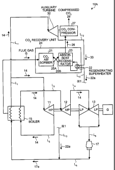
human activities that involve burning of fossil fuels are
CO2 generation sources, and needs for CO2 emission
limitation are becoming increasingly great. Accordingly,
methods that enable to bring flue gas of a boiler into
contact with an amine CO2 absorbent to reduce or recover
CO2 in the flue gas, and methods that enable to store
recovered CO2 without releasing CO2 to the atmosphere have
been intensively studied for power-generating facilities
such as thermal power plants that use a large amount of
fossil fuels. As steps that enable to reduce or recover
CO2 from flue gas by using a CO2 absorbent as described
above, a step of bringing flue gas into contact with a CO2
absorbent in an absorber and a carbon dioxide recovery
system that heats an absorbent having absorbed CO2 in a
regenerator to liberate CO2 as well as regenerates the
absorbent and circulates the regenerated absorbent again in
the regenerator to reuse the absorbent are adopted.
[0003] This carbon dioxide recovery system causes carbon
dioxide contained in gas in the absorber to be absorbed by
1
CA 02765896 2013-09-09
53609-34
the absorbent and then be heated in the regenerator,
thereby separating the carbon dioxide from the absorbent,
so that the separated carbon dioxide is separately
recovered and a regenerated absorbent is cyclically used
again in the absorber.
[0004] To separate and recover carbon dioxide in the
regenerator, the absorbent needs to be heated by a
regenerating superheater and heating steam at a prescribed
pressure needs to be supplied thereto. When CO2 is to be
recovered from flue gas of a practical power plant, a large
amount of steam is required to regenerate the absorbent.
[0005] To supply the steam, methods that enable to bleed
= steam from a steam turbine of a power generation system,
that enable to bleed steam from each header between a high-
pressure turbine (HP) and an intermediate-pressure turbine
(MP) or between an intermediate-pressure turbine (MP) and a
low-pressure turbine (LP), or that enable to recover power
from bled steam using a steam turbine and supply emission
to a regenerating superheater in a CO2 recovery system have
been proposed (see Japanese Patent Application Laid-open No.
2004-323339).
Citation List
Patent Literature
[0006] Patent Literature 1: Japanese Patent Application
Laid-open No. H03-193116
Patent Literature 2: Japanese Patent Application Laid-
open No. 2004-323339
Summary
[0007] The methods mentioned above involve significant
modification of a steam system or installation of a turbine
in the existing power generation system and also, both in
the existing and newly-built power generation systems,
2
=
Mk 02765896 2013-09-09
53609-34
greatly change the steam pressure along with changes in loads
of power-generating facilities or changes in steam to be used
in the CO2 recovery system or a use amount thereof while the
CO2 recovery system uses steam at a fixed pressure. Therefore,
quite complicated system control is required to address these
situations.
Besides, because these systems use superheated steam
for the regenerating superheater to recover 002, the steam is
used by decreasing the temperature with water before the steam
enters the regenerating superheater and accordingly there is
energy loss in the steam pressure.
[0008] Embodiments of the present disclosure seek to provide
a carbon dioxide recovery system and a carbon dioxide recovery
method that enable to reliably regenerate a carbon dioxide
absorbent without imposing loads on a boiler and steam turbine
facilities.
[0008a] According to an aspect of the present invention,
there is provided a carbon dioxide recovery system comprising:
a boiler for generating steam; a high-pressure turbine, an
intermediate-pressure turbine, and a low-pressure turbine which
are driven by the steam generated by the boiler and in response
to load variation of the boiler; a carbon dioxide recovery unit
that includes a carbon dioxide absorber for absorbing and
reducing carbon dioxide in flue gas emitted from the boiler
using a carbon dioxide absorbent, and an absorbent regenerator
for regenerating a carbon dioxide absorbent having absorbed the
carbon dioxide using a regenerating superheater to obtain a
3
CA 02765896 2013-09-09
53609-34
regenerated carbon dioxide absorbent; a high-temperature and
high-pressure steam extraction line for piping high-temperature
and high-pressure steam from the boiler to the high-pressure
turbine; auxiliary turbine means for recovering power using the
extracted high-temperature and high-pressure steam; and a steam
supply line for supplying emission steam emitted from the
auxiliary turbine to the regenerating superheater of the carbon
dioxide regenerator to be used as a heat source.
[0008b] In some embodiments, the auxiliary turbine means
comprises a high-pressure auxiliary turbine and a low-pressure
auxiliary turbine for recovering power with the extracted high-
temperature and high-pressure steam, wherein intermediate-
pressure steam obtained by reheating in the boiler emission
steam from the high-pressure turbine is extracted before being
introduced into the intermediate-pressure turbine, and heat
exchange between the emission steam from the high-pressure
auxiliary turbine and the reheated intermediate-pressure steam
is performed in a heat exchanger.
[0008c] In some embodiments, the emission steam from the
high-pressure auxiliary turbine is reheated in the boiler and
introduced into the low-pressure auxiliary turbine.
[0009] According to another aspect, a carbon dioxide
recovery system includes: a high-pressure turbine, an
intermediate-pressure turbine, and a low-pressure turbine; a
boiler that generates steam for driving these turbines; a
carbon dioxide recovery unit that includes a carbon dioxide
absorber that absorbs and reduces carbon dioxide in flue gas
emitted from the boiler using a carbon dioxide absorbent, and
an absorbent regenerator that regenerates a carbon dioxide
3a
CA 02765896 2013-09-09
53609-34
absorbent having absorbed the carbon dioxide using a
regenerating superheater to obtain a regenerated carbon dioxide
absorbent; a high-temperature and high-pressure steam
extraction line that extracts high-temperature and high-
pressure steam from the boiler before the steam is introduced
into the high-pressure turbine; an auxiliary turbine that
recovers power using the extracted
3b
CA 02765896 2013-09-09
53609-34
high-temperature and high-pressure steam; and a steam
supply line that supplies emission steam emitted from the
auxiliary turbine to the regenerating superheater of the
carbon dioxide regenerator to be used as a heat source.
[0010] In some embodiments, the carbon dioxide recovery
system further includes a high-pressure auxiliary turbine
and a low-pressure auxiliary turbine that recover power
with the extracted high-temperature and high-pressure steam.
Intermediate-pressure steam obtained by reheating in the
boiler emission from the high-pressure auxiliary turbine is
extracted before being introduced into the intermediate-
pressure turbine, and heat exchange between the emission
from the high-pressure auxiliary turbine and the reheated
intermediate-pressure steam is performed in a heat
exchanger.
[0011] In some embodiments, the carbon dioxide recovery
system further includes the high-pressure auxiliary turbine
and the low-pressure auxiliary turbine that recover power
with the extracted high-temperature and high-pressure steam.
The emission from the high-pressure auxiliary turbine is
reheated in the boiler and introduced into the low-pressure
auxiliary turbine.
[0012] Another aspect of the present invention is a
carbon dioxide recovery method of recovering carbon dioxide
absorbed in the carbon dioxide absorbent using the carbon
dioxide recovery system according to any one of described
above.
[0013] According to the present invention, the high-
temperature and high-pressure steam from the boiler is
extracted through the extraction line before being supplied
to the high-pressure turbine, power is recovered by the
auxiliary turbine using the extracted steam, and steam
4
CA 02765896 2013-09-09
53609-34
emitted from the auxiliary turbine is supplied to the
regenerating superheater. Therefore, also when operation
loads of the boiler or the steam turbine of the power
generation system vary, stable steam for the regenerating
superheater can be supplied and regeneration of the
absorbent can be reliably performed, resulting in stable
recovery of carbon dioxide.
Brief Description of Drawings
[0014] FIG. 1 is a schematic diagram of a carbon dioxide
recovery system according to a first embodiment of the
present invention.
FIG. 2 is a schematic diagram of a carbon dioxide
recovery system according to a second embodiment of the
present invention.
FIG. 3 is a schematic diagram of a carbon dioxide
recovery system according to a modified second embodiment
of the present invention.
FIG. 4 is a schematic diagram of a carbon dioxide
recovery system according to a conventional technique.
Description of Embodiments
[0015] Examples of embodiments of the present invention
will be explained below in detail with reference to the accompanying
drawings. The present invention is not limited to the embodiment, and
when there are a plurality of embodiments, configurations
made by combining these embodiments are also included
as embodiments of the present invention. In addition,
constituent elements in the following embodiments include those
that can be easily assumed by persons skilled in the art, or
that are substantially equivalent.
[First embodiment]
[0016] A carbon dioxide recovery system according to a
first embodiment of the present invention is explained with
reference to the drawings. FIG. 1 is a schematic diagram
5
CA 02765896 2012-01-25
DocketNo.PMHA-11046-CA
of a carbon dioxide recovery system according to the first
embodiment.
As shown in FIG. 1, a carbon dioxide recovery system
10A includes a high-pressure turbine 11, an intermediate-
pressure turbine 12, a low-pressure turbine 13, a boiler 15
that generates steam 14 for driving these turbines, a
carbon dioxide recovery unit (CO2 recovery unit) 24
including a carbon dioxide absorber (002 absorber) 21 that
absorbs and reduces carbon dioxide in flue gas (emission
gas) G emitted from the boiler 15 using a carbon dioxide
absorbent, and an absorbent regenerator 23 that regenerates
a carbon dioxide absorbent having absorbed the carbon
dioxide using a regenerating superheater 22 to obtain a
regenerated carbon dioxide absorbent, a high-temperature
and high-pressure steam extraction line Lll that extracts
the high-temperature and high-pressure steam 14 from the
boiler 15 before the steam is introduced into the high-
pressure turbine 11, an auxiliary turbine 32 that recovers
power using the extracted high-temperature and high-
pressure steam 14, and a steam supply line L12 that
supplies emission steam 33 emitted from the auxiliary
turbine 32 to the regenerating superheater 22 of the
absorbent regenerator 23 to be used as a heat source.
Reference sign 17 denotes a condenser, 17a and 22a
denote condensed water, L1 denotes a supply line for the
high-temperature and high-pressure steam 14, L2 to L5
denote steam lines, L6 denotes a supply line for the
condensed water 17a, and L13 denotes a supply line for the
condensed water 22a.
[0017] The carbon dioxide absorbent is composed of a
carbon dioxide absorbent (rich solution) 25A that has
absorbed carbon dioxide in the CO2 absorber 21 and a
regenerated carbon dioxide absorbent (lean solution) 25B
6
CA 02765896 2012-01-25
DocketNo.PMHA-11046-CA
that is regenerated by releasing carbon dioxide using the
regenerating superheater 22 in the regenerator 23, and the
absorber 21 and the regenerator 23 are cyclically reused.
CO2 gas 26 accompanied by water vapor emitted from the
absorbent regenerator 23 is compressed by a CO2 compressor
27 to obtain compressed CO2 28.
[0018] The high-pressure and high-temperature steam 14
generated and heated by the boiler 15 drives the high-
pressure turbine 11, then is resuperheated by a
resuperheater (not shown) in the boiler 15 as high-pressure
turbine emission, and sent to the intermediate-pressure
turbine 12 and then to the low-pressure turbine 13 as
resuperheated intermediate-pressure steam.
[0019] Emission from the low-pressure turbine 13 is
condensed by the condenser 17, and condensed water 17a is
sent to the boiler as boiler supply water.
[0020] An amine absorbent can be cited as an example of
the carbon dioxide absorbent that absorbs CO2.
Specifically, monoethanolamine, diethanolamine,
triethanolamine, methyldiethanolamine, diisopropanolamine,
and diglycolamine as alkanolamine, and also hindered amines
can be cited as examples. Solutions of one of these or
mixed solutions of two or more of these can be also cited.
Usually, a monoethanolamine solution is preferably used.
[0021] In the present invention, before being supplied
to the high-pressure turbine 11, the high-temperature and
high-pressure steam 14 is extracted from the boiler 15
through the extraction line L11, and power is recovered by
the auxiliary turbine 32 using the extracted steam. The
emission steam 33 emitted from the auxiliary turbine 32 is
then used and supplied through the steam supply line 1,12 as
a heat source to the regenerating superheater 22 that is
used when the carbon dioxide absorbent 25A having absorbed
7
CA 02765896 2012-01-25
DocketNo.PMHA-11046-CA
carbon dioxide is to be regenerated in the carbon dioxide
regenerator 23.
[0022] In the present embodiment, the auxiliary turbine
32 drives the 002 compressor 27 to compress the 002 gas 26
accompanied by the water vapor emitted from the absorbent
regenerator 23 to obtain the compressed 002.
Instead of supplying the 002 gas to the 002 compressor
27, a power generator can be driven to introduce the
emission steam 33 into the regenerating superheater 22 of
the 002 recovery unit 24.
[0023] As a result, even when there is load variation
(100% to 50%) of the boiler 15 and the steam turbines (the
high-pressure turbine 11, the intermediate-pressure turbine
12, and the low-pressure turbine 13), the high-pressure
turbine, the intermediate-pressure turbine, and the low-
pressure turbine change according to the load variation and
generate power. Accordingly, no influence is exerted on
the power generation system and stable steam is supplied to
the regenerating superheater 22 in the 002 recovery unit
from the auxiliary turbine 32 using the extracted high-
temperature and high-pressure steam 14. As a result, 002
recovery can be stably performed.
[0024]
[Test example]
FIG. 4 is a schematic diagram of a carbon dioxide
recovery system 100 according to a conventional technique.
As shown in FIG. 4, the carbon dioxide recovery system
according to the conventional technique includes an
auxiliary turbine 18 that extracts steam from a middle
portion between the intermediate-pressure turbine 12 and
the low-pressure turbine 13 and recovers power using the
steam. This recovery system uses emission steam 19 emitted
from the auxiliary turbine 18 as a heat source of the
8
ak 02765896 2012-01-25
Docket No. PMHA-11046-CA
regenerating superheater 22 of the carbon dioxide
regenerator 23.
[0025] For example, recovery of CO2 from flue gas in a
1,000-MW coal combustion thermal power plant was examined.
An amount of steam of an ultra-super critical pressure
boiler of the 1,000-MW coal combustion thermal power plant
is 2,836 tons (T)/hour (H), and an amount of CO2 generated
from boiler flue gas is 733 T/H.
When assuming that 90% of CO2 is recovered, an amount
of recovered CO2 is 660 T/H (15,840 T/D).
An amount of steam required by the CO2 recovery unit
24 associated with the CO2 recovery is 792 T/(3-kgG
saturated water vapor conversion).
Table 1 shows this result.
It is confirmed in Table 2 that, in a case where a
steam turbine output is 880 MW, 95 MW is consumed as CO2
compressor power and the like and that the total output is
785 MW, resulting in an output decrease by about 21.5% in
total.
[0026] Also in the system of the present invention, the
same result as that in the conventional technique is
obtained as shown in Table 3.
[0027] Therefore, it is confirmed that output decreases
in the case where the conventional auxiliary turbine is
used and in the case where the system of the present
invention is used are equal and that the system can be
operated more stably in the case where the auxiliary
turbine is driven by the high-temperature and high-pressure
steam extracted from the boiler of the present invention
through the high-temperature and high-pressure steam
extraction line when the load variation in the power-
generating facilities is considered.
[0028]
9
CA 02765896 2012-01-25
DocMANoJWFM-11M-CA
[Table 1]
(Table 1)
1,000 MW ultra-super critical
pressure boiler
Steam 2,836 T/H
002 generation amount 733 T/H
660 T/H (90%
002 recovery amount
recovery)=15,840 T/D
Steam required to recover 002 792 T/H (3 KgG. saturation)
[0029]
[Table 2]
(Table 2)
Steam turbine output 880 MW
002 compressor power etc.
95 MW
(consumption)
Total output 785 MW
Output decrease 21.5%
[0030]
[Table 3]
(Table 3)
1,000 MW ultra-super critical
pressure boiler
Steam 2,836 T/H
002 generation amount 733 T/H
660 T/H (90%
002 recovery amount
recovery)=15,840 T/D
Steam required to recover 002 792 T/H (3 KgG. Saturation)
Steam turbine output 880 MW
002 compressor power etc.
95 MW
(consumption)
Total output 785 MW
Output decrease 21.5%
CD, 02765896 2012-01-25
DocketNo.PMHA-11046-CA
[Second embodiment]
[0031] A carbon dioxide recovery system according to a
second embodiment of the present invention is explained
with reference to the drawings. FIG. 2 is a schematic
diagram of a carbon dioxide recovery system according to
the second embodiment. FIG. 3 is a schematic diagram of
another carbon dioxide recovery system according to the
second embodiment.
As shown in FIG. 2, a carbon dioxide recovery system
10B according to the second embodiment includes two steam
turbines in the carbon dioxide recovery system 10A of the
first embodiment, in which one of the steam turbines is a
high-pressure auxiliary turbine 32H and the other is a low-
pressure auxiliary turbine 32L.
[0032] Intermediate steam 14 obtained by reheating in
the boiler 15 the emission from the high-pressure turbine
11 is extracted by an extraction line L21 before being
introduced into the intermediate-pressure turbine 12, and a
heat exchanger 36 is interposed on the extraction line L21.
The heat exchanger 36 is provided on the supply line LN
for supplying emission from the high-pressure auxiliary
turbine 32H, and heat exchange between the resuperheated
intermediate steam and the emission from the high-pressure
auxiliary turbine 32H is performed in the heat exchanger 36.
In this way, the emission 14 to be supplied to the low-
pressure auxiliary turbine 32L is reheated.
As a result, the emission from the auxiliary turbine
can be reheated without using a reheater in the boiler 15.
[0033] As shown in FIG. 3, in a carbon dioxide recovery
system 10C, emission from the high-pressure turbine 32H is
reheated in the boiler 15 to be used in the low-pressure
turbine 32L.
11
CA 02765896 2012-01-25
,
DocketNo.PMHA-11046-CA
Reference Signs List
[0034] 10A, 10B carbon dioxide recovery system
11 high-pressure turbine
12 intermediate-pressure turbine
13 low-pressure turbine
14 steam
boiler
G flue gas
21 carbon dioxide absorber (absorber)
10 22 regenerating superheater
23 absorbent regenerator (regenerator)
24 carbon dioxide recovery unit
31 steam
32 auxiliary turbine
15 32H high-pressure auxiliary turbine
32L low-pressure auxiliary turbine
33 emission steam
12