Note: Descriptions are shown in the official language in which they were submitted.
=
BAKERY TRAY
BACKGROUND
Bakery trays typically include a base from which front, rear and side walls
extend
upward. The side walls may include feet that are arranged relative to recesses
at upper edges
of the side walls such that the tray can stack with an identical tray at a
first orientation and nest
(or stack at a different height) with the identical tray at a second
orientation, where the second
orientation is 180 relative to the first orientation.
When many of these trays are stacked or nested, a substantial portion of the
weight from
each tray and the trays above it is transferred to the tray below via the
feet. However, for the
bottom tray on the floor, the feet may not contact the floor. Rather, the
bottom tray is supported
on drag rails, which are inward of the feet. Thus, the weight of all the trays
above the bottom
tray bears on the bottom tray at points outward of the drag rails, which may
cause the side walls
of the bottom tray to twist outward.
SUMMARY
A tray having one feature disclosed herein includes a base and a plurality of
walls
extending upward from the base. A first wall of the plurality of walls
includes a projection
outward from the first wall. The projection is aligned with an upper edge of
the first wall, such
that the projection is outward of a portion of the upper edge of the first
wall. In this manner,
the projection of an identical upper tray stacked on the tray would interlock
with the upper edge
of the first wall to resist outward deflection of the upper edge of the first
wall of the tray.
In one embodiment disclosed herein, the projection has a T-shaped cross-
section,
complementary to a T-shaped recess in the upper edge of the first wall.
A tray having another feature disclosed herein includes a base and a plurality
of walls
extending upward from the base. A platform extends inwardly from at least one
of the walls.
1
CA 2765979 2018-03-28
CA 02765979 2012-01-27
The platform can be used to support smaller trays stacked thereon. For
example, trays that are
approximately half the size of the tray can be supported on three of the walls
and the platform.
In the embodiment disclosed herein as one example, platforms extend inwardly
from an
opposing pair of the walls to support the half-size trays.
In a tray having another feature disclosed herein, a base includes front and
rear walls
extending upward from front and rear edges of the base. Side walls extend
upward from side
edges of the base. Each of the side walls includes at least one interlocking
recess for receiving
automated handling equipment for supporting the tray.
In one specific example disclosed herein, each interlocking recess is defined
by a
curved upper wall protruding outwardly from the side wall.
BRIEF DESCRIPTION OF THE DRAWINGS
Figure 1 is a perspective view of tray according to a first embodiment.
Figures 2A and 2B are side views of the tray.
Figure 3 is a front view of the tray.
Figure 4 is bottom perspective view of the tray.
Figure 5 is a top view of the tray.
Figure 6 is a perspective view of the tray with an identical tray stacked
thereon in a
low stack position.
Figure 7 is a side view of the trays of Figure 6.
Figure 8 is a perspective view of the trays of Figure 6 in a high stacked
position.
Figure 9 is a side view of the trays of Figure 8.
Figure 10 is a perspective view of the tray with an identical tray being slide-
stacked
onto the tray.
Figure 11 is an enlarged front view a portion of the trays of Figure 10.
Figure 12 is a perspective view of the tray stacked onto smaller prior art
trays and
having two prior art trays stacked thereon.
Figure 13 is a front view of the trays of Figure 12.
Figure 14 is a side view of the trays of Figure 12.
Figure 15 shows the trays of Figure 12 with one of the upper trays removed.
2
CA 02765979 2012-01-27
=
Figure 16 is an enlarged perspective view of one of the platforms supporting
the prior
art tray.
Figure 17 is a cut-away view through the platform of Figure 16.
Figure 18 is an enlarged view of the platform of Figure 17.
Figure 19 is a perspective view of a halved tray (for purpose of illustration)
stacked on
the prior art tray.
Figure 20 is an enlarged view of a portion of Figure 19.
Figure 21 is another enlarged view of a portion of Figure 19.
Figure 22 is a bottom perspective view of a portion of the base of the tray.
Figure 23 is a perspective view of one side wall of the tray.
Figure 24 shows the prior art tray in one orientation stacked on the side wall
of Figure
23.
Figure 25 shows the prior art tray in the other orientation stacked on the
side wall of
Figure 23.
Figure 26 is a perspective view of the other side wall of the tray.
Figure 27 shows the prior art tray stacked on the side wall of Figure 26 in
one
orientation.
Figure 28 shows the prior art tray stacked on the side wall of Figure 26 in
the other
orientation.
Figure 29 is a perspective view of one side wall of the prior art tray.
Figure 30 is a perspective view of the other side wall of the prior art tray.
Figure 31 shows one side wall of the tray stacked on one of the side walls of
the prior
art tray.
Figure 32 shows the tray stacked on the other side wall of the prior art tray.
Figure 33 shows the other side wall of the tray stacked on one of the side
walls of the
prior art tray.
Figure 34 shows the other side walls of the tray stacked on the other side
wall of the
prior art tray.
Figure 35 is a perspective view of one side wall of the tray having a portion
of
automated handling equipment engaged therewith.
3
CA 02765979 2012-01-27
Figure 36 shows the side wall of Figure 35 with the automated handling
equipment
disengaged therefrom.
Figure 37 is a front view of the tray and the automated handling equipment
engaged
therewith.
Figure 38 is a front view of the tray with the automated handling equipment
disengaged therefrom.
Figure 39 is a perspective view of a bakery tray according to a second
embodiment.
Figure 40 is an interior perspective view of one side wall of the tray of
Figure 39.
Figure 41 is an exterior perspective view of one of the side walls of the tray
of Figure
39.
Figure 42 is a bottom perspective view of the side wall of Figure 41.
Figure 43 shows the tray of Figure 39 with an identical tray stacked thereon
in the high
stacked position.
Figure 44 is a section view through the trays of Figure 43.
Figure 45 is a perspective view of the trays of Figure 43 in the low stacked
position.
Figure 46 is a section view through the trays of Figure 45.
Figure 47 is a perspective view of the trays of the Figure 45 with the upper
tray being
lifted at one end.
Figure 48 is a section view through the trays of Figure 47.
DETAILED DESCRIPTION OF THE PREFERRED EMBODIMENT
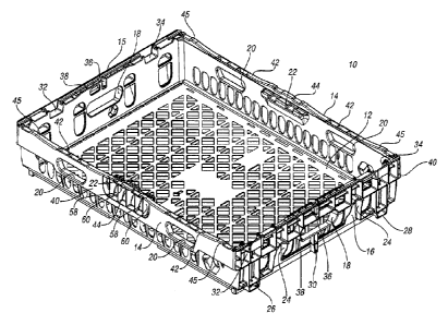
A bakery tray 10 according to one embodiment of the present invention is shown
in
Figure 1. The bakery tray 10 generally includes a base 12, front and rear
walls 14 extending
upwardly from front and rear edges of the tray 10, and side walls 15, 16
extending upwardly
from side edges of the base 12. The side walls 15, 16 include handles 18
formed therein.
Each of the front and rear walls 14 includes a pair of handles 20 formed
therein. Each of the
front and rear walls 14 includes a platform 22 projecting inwardly adjacent an
upper edge
thereof and centered between the handles 20. The platform 22 is generally
hollow with
openings 58 to the exterior of the tray 10 between ribs 60.
Each of the side walls 15, 16 includes a pair of interlocking recesses 24 for
interlocking with automated handling equipment. Each side walls 15, 16 further
includes a
4
CA 02765979 2012-01-27
rear foot 26, front foot 28, and center projection 30 projecting downwardly.
The front foot 28
is adjacent the front edge of the tray 10 while the rear foot 26 is spaced
away from the rear
edge of the tray 10. An upper edge of each side wall 15, 16 includes a rear
recess 32 aligned
with the rear foot 26, a front recess 34 aligned with the front foot 28 and a
center recess 36
aligned with the center projection 30. An inner rail 38 extends across
portions of the side
walls 15, 16. The front and rear walls 14 include a double-walled lip portion
40 that projects
outwardly relative to a lower portion of the front and rear walls 14. The
upper edge of the
front and rear walls 14 each include a raised central portion 44 adjacent the
platform, a
recessed portion 42 between the raised central portion 44 and each side wall
15, 16, and an
outer raised portion 45 adjacent each side wall 15, 16.
Figures 2A and 2B show the two sides of the tray 10. Figure 2A shows the same
side
wall 16 as Figure 1. Figure 2B shows the opposite side wall 15. As shown in
Figure 2A, on
side wall 16, the feet 26, 28 are spaced further outward (toward front and
rear walls 14), while
in Figure 2B, on side wall 15, the feet 26, 28 are spaced further inward (away
from front and
rear walls 14). This is one way of providing stacking at a high stack position
in one
orientation and at a low stack position (or alternatively, nesting) in another
(180 degree)
orientation.
Figure 3 is a front view of the tray 10.
Figure 4 is a bottom perspective view of the tray 10. The base 12 includes a
upper,
planar panel portion 90 with a plurality of cross-ribs 92 projecting downward
therefrom,
including a peripheral rib 94 extending along most of the periphery of the
front and rear walls
14. Each peripheral rib 94 includes a recessed portion 96, where the
peripheral rib 94 juts
inwardly to expose a portion 98 of the planar panel portion 90. The exposed
portion 98 of the
upper planar portion 90 is aligned with the platform 22 (Figure 1). As a
result, when one tray
10 is stacked on another tray 10, the platforms 22 of the lower tray 10 will
be received within
the recessed portions 96 of the peripheral ribs 94 of the upper tray 10 and
the ribs 92, 94 will
not impact the platforms 22 and prevent proper stacking of the trays 10. Drag
rails 100 extend
downward from the base 12 inward of each side wall 15, 16. The drag rails 100
may be
double-walled drag rails 100 with cross-ribs, as shown. The bottom surface of
the feet 26, 28
on the side wall 15 each include a central recess 27, while the feet 26, 28 on
the side wall 16
5
CA 02765979 2012-01-27
each include a lateral recess 29, such that the lateral recesses 29 are open
laterally facing one
another.
Figure 4 also shows the interlocking recesses 24. Each side wall 15, 16
includes a
plurality of ribs 66 extending outwardly of a planar wall portion. Ribs 68
partially define the
interlocking recess 24. The ribs 68 form an upper curved wall and two
generally vertical
walls. A plurality of vertical ribs 72 extend downward from the upper curved
wall to increase
the strength and rigidity of the upper curved wall and to provide more
gripping with the
automated handling equipment.
Figure 5 is a top view of the tray 10.
Figures 6-7 show the tray 10 with a similar tray 10' stacked thereon in a low
stack
position, i.e., in a similar orientation with the front feet 28' received in
the front recesses 34
and the rear feet 26' received in the rear recesses 32. The center projections
30' are received
in the center recesses 36.
In Figures 8-9, the upper tray 10' is rotated 1800 and is stacked on the lower
tray 10 in
a high stack position, i.e., with the rear feet 26' stacked on the upper edge
of the side walls 16
and the front feet 28' stacked on the upper edge of the side walls 16, not
received in the
recesses 32, 34. In the high stack position, larger goods or more layers of
goods can be placed
in the lower tray 10.
Figures 10-11 illustrate the upper tray 10' as it is being slide-stacked onto
the lower
tray 10. Referring to Figure 11, the upper edge of the front and rear walls 14
(front and rear
walls 14 are symmetric about longitudinal and lateral axes in this embodiment)
is shown in
more detail. The upper edge of the front and rear walls 14 each includes the
recessed portion
42 and an outer raised portion 45. A notch 102 is formed in the outer raised
portion 45 to
accommodate the drag rail 100' of the upper tray 10'. The feet 26' of the
upper tray 10' rest
on the inner rail 38 of the lower tray 10 and an upper surface 105 of the side
wall 16. A
downward projection from the central projection 30' of the upper tray 10'
extends into an
outer notch 104 in the upper edge of the bottom tray 10. An outer rail 106
projects upwardly
from the side wall 16 outward of the upper tray 10'.
As shown in Figure 12, the tray 10 can support thereon and be supported on two
prior
art trays 110 that are approximately half the size of the tray 10. The prior
art tray 110 includes
a base 112, front and rear walls 114 and side walls 116. The prior art tray
110 is symmetric
6
CA 02765979 2012-01-27
about the long axis, i.e. the side walls 116 are mirror images of one another.
The front and rear
walls 114 each include a plurality of vertical ribs 117 on an exterior surface
thereof. The
lower ends of the ribs 117 are aligned along an arc and therefore are not
sufficient for stably
supporting the prior art tray 110 on the front and rear walls 14 of the tray
10. Thus, the front
and rear walls 114 of the prior art tray 110 are also supported on the
platforms 22.
The prior art tray 110 includes rear support columns 118 having three
castellations 120
on an upper support surface thereof Front support columns 122 each have a
single
castellation 124 on an upper support surface thereof.
As shown in Figure 13, the vertical ribs 117 of the prior art trays 110 align
with the
recessed portion 42 of the upper edge of the front and rear walls 14.
Referring to Figure 14, the feet 26 of the tray 10 contact the upper surface
of the rear
support columns 118 rearward of the castellations 120. The feet 28 contact the
upper surface
of the front support columns 120 rearward of the castellation 124.
Figures 15-17 show the trays 10, 110 of Figure 12 with one upper prior art
tray 110
removed. Figure 16 is an enlarged view of one of the platforms 22 (the other
is identical)
supporting the prior art tray 110. The platform 22 extends inwardly from an
inner surface of
each front and rear wall 14. The platform 22 includes a central support
surface 46 spaced
away from outer support surfaces 48. A ridge 50 projects upwardly from an
inner edge of the
central support surface 46. Ridges 52 project upwardly from inner edges of the
outer support
surfaces 48. Lower surfaces 54 are between each outer support surface 48 and
the central
support surface 46. A rib 113 extending downwardly from the base 112 of the
prior art tray
110 is supported on the lower surface 54 of the platform 22.
Figure 17 is a cutaway view through the platform 22 of Figure 16. Figure 18 is
an
enlarged view of the platform 22 of Figure 17. The platform 22 is generally
hollow with
openings 58 to the exterior of the tray 10 adjacent ribs 60.
Figures 1 9-2 1 show a halved tray 10 (for purpose of illustration) stacked on
the prior
art tray 110. Referring to Figure 20, the base 12 of the tray 10 can be viewed
as an upper,
planar panel portion 90 from which a plurality of cross-ribs 92 extend
downward. The
recessed portion 96 of the peripheral rib 94 is supported on the upper support
surface of the
front column portion 122 inward of the single castellation 124. Referring to
Figure 21, the
cross-ribs 92 of the base 12, are supported on the rear column portion 118
between the
7
CA 02765979 2012-01-27
castellations 120. Figure 22 is a bottom perspective view of the cross-ribs 92
and peripheral
rib 94, showing the arrangement to accommodate the castellations 120, 124
(Figures 20-21).
Figures 23-25 together illustrate the alignment of the prior art tray 110 on
the side wall
16 of the tray 10. Figure 23 shows the side wall 16. The rear foot 26 and
front foot 28 are
each outward of a window 128, which is outward of the interlocking recess 24.
The rear
recess 32 and front recess 34 are therefore also aligned outward of the
windows 128.
Referring to Figure 24, in one orientation, the rear foot 130 of the prior art
tray 110 is
supported on the side wall 16 outward of the recess 32, while the front foot
132 of the prior art
tray is supported on the side wall 16 inward of the recess 34.
Referring to Figure 25, in the other orientation, the rear foot 130 is
supported outward
of the recess 34, while the front foot 132 is supported inward of the recess
32.
Figures 26-29 illustrate the alignment of the prior art tray 110 on the side
wall 15 of
the tray 10. Figure 26 shows the side wall 15. The rear foot 26 and front foot
28 are each
inward of a window 128 and immediately adjacent the interlocking recess 24.
The rear recess
32 and front recess 34 are therefore also aligned inward of the windows 128.
Figure 27 shows
one orientation of the prior art tray 110, in which the rear foot 130 of the
prior art tray 110 is
supported on the side wall 16 outward of the recess 34, while the front foot
132 of the prior art
tray is supported on the side wall 16 outward of the recess 32. Referring to
Figure 28, in the
other orientation, the rear foot 130 is supported outward of the recess 32,
while the front foot
132 is supported inward of the recess 34.
Figures 29 and 30 are upper perspective views of the side walls 116 of the
prior art
tray 110. Figures 31 and 32 show the side wall 15 of the tray 10 stacking on
the side walls
116 of the prior art tray 110. In Figure 31, the front foot 28 is stacked on
the side wall 116,
while the rear foot 26 is stacked on the rear support column 118. One of the
castellations 120
is received in the central recess 27 (Figure 4) of the rear foot 26, adjacent
the drag rail 100.
On the other side wall 116, shown in Figure 32, the rear foot 26 is stacked on
the side wall
116, while the front foot 28 is stacked on the rear support column 118, with
one of the
castellations 120 received in the central recess 27 (Figure 4) of the front
foot 28, adjacent the
drag rail 100.
Figures 33 and 34 show the side wall 16 of the tray 10 stacking on the side
walls 116
of the prior art tray 110. In Figure 33, the front foot 28 is stacked on the
rear support column
8
= ..
v
4
118, with one of the castellations 120 received in the lateral recess 29
(Figure 4) of the front
foot 28, adjacent the drag rail 100. The rear foot 26 is stacked on the front
support column 122.
On the other side wall 116, shown in Figure 34, the rear foot 26 is stacked on
the rear support
column 118, with one of the castellations 120 received in the lateral recess
29 (Figure 4) of the
rear foot 26, adjacent the drag rail 100. The front foot 28 is stacked on the
front support column
122.
Automated handling equipment may include a lifting and pulling device, such as
the
device 80 shown in Figures 35-38. The device 80 includes a center bar 82
having hinge pins
84 projecting from each axial end. Arms 86 extend downward from the center bar
82. A
projection 88 is formed at the outer end of each arm 86. As shown in Figure 37
and 38, the
device 80 can be used to engage the interlocking recesses 24 in either end of
the tray 10. The
projection 88 at the end of each arm 86 provides some self-alignment between
the device 80
and the tray 10. The device 80 can lift and pull the tray 10.
Figure 39 is a perspective view of a bakery tray 210 according to a second
embodiment.
The bakery tray 210 is identical to the tray 10 of the first embodiment except
as otherwise
described below or as shown in the Figures. The bakery tray 210 generally
includes a base 212,
front and rear walls 214 extending upwardly from front and rear edges of the
tray 210, and side
walls 215, 216 extending upwardly from side edges of the base 212. The side
walls 215, 216
include handles 218 formed therein. Each of the front and rear walls 214
includes a platform
222 projecting inwardly adjacent an upper edge thereof and centered between
the handles 220.
Each of the side walls 215, 216 includes a pair of interlocking recesses 224
for
interlocking with automated handling equipment. Each side walls 215, 216
further includes a
rear foot 226, front foot 228, and center projection 230 projecting
downwardly. Recesses in the
upper edge of the side walls 215, 216 provide for different stacking heights;
however, in this
embodiment, the recesses for the high stacking position are positioned
directly above the feet
226, 228 so that load can transfer directly from foot to foot in the high
stacking position (in the
low stacking position, there are many other contact areas between the upper
tray and the lower
tray in addition to the feet in the low-stacking recesses).
An upper edge of each side wall 215, 216 includes a center recess 236 above
the handles
218 and aligned with the center projection 230.
9
CA 2765979 2018-03-28
=
4
The center recess 236 is shown more clearly in Figure 40. The center recess
236 is T-
shaped including a large portion 237 and a narrow portion 239, as defined by
two wall portions
241.
The center projection 230 is shown in more detail in Figure 41. The center
projection
230 is also T-shaped, having a single-wall thickness base rib 273 extending
outward from the
side wall 216 (the projection side wall 215 can be identical) to outer cross
portion 274 generally
parallel to the side wall 216. Outer cross portion 274 includes a pair of
vertical ribs 275 each
having a tapered, narrow portion 276 above their bottom edges and above the
bottom edge of
the outer cross portion 274. The narrow portions 276 are preferably curved,
concave portions.
A bottom horizontal rib 277 extends across the bottom of the vertical ribs 275
defining the
bottom of the cross portion 274.
A bottom view of the tray 210 is shown in Figure 42, where the center
projection 230 is
also shown.
In Figure 43, the tray 210 is shown with an identical tray 210 stacked thereon
in the high
stack position. The center projection 230 of the upper tray 210 is partially
received in the center
recess 236 of the lower tray 210. The interlocking T-shapes of the center
projection 230 and
center recess 236 prevent the side walls 215, 216 of the lower tray 210 from
bowing outward
under the weight of the tray 210 and numerous other trays 210 stacked in turn
thereon, which
may each be loaded with goods. As shown in Figure 44, the base rib 273 of the
center projection
230 is received between the wall portions 241 of the center recess 236,
thereby capturing the
cross portion 274 of the center projection 230 of the upper tray 210, thereby
preventing the side
wall of the lower tray 210 from bowing outward.
In Figures 45 and 46, the trays 210 are in the low stacked position. The
center projection
230 of the upper tray 210 is received fully within the center recess 236 of
the lower tray 210.
If the upper tray 210 is lifted at the opposite side, as shown in Figures 47
and 48, this
pivots the center projection 230 within the center recess 236. The narrow
portions 276 of the
vertical ribs 275 accommodate and receive the front edge of the side wall as
the upper tray 210
is pivoted. Thus, the center projection 230 reinforces the side wall of the
lower tray 210 during
stacking, but also permits the upper tray 210 to pivot when stacked.
10
CA 2765979 2018-03-28
. .
In accordance with the provisions of the patent statutes and jurisprudence,
exemplary
configurations described above are considered to represent a preferred
embodiment of the
invention. However, it should be noted that the invention can be practiced
otherwise than as
specifically illustrated and described without departing from its scope.
11
CA 2765979 2018-03-28