Note: Descriptions are shown in the official language in which they were submitted.
CA 02766003 2011-12-19
Pressure retention valve
The present invention concerns a pressure retention valve
comprising a housing having an inlet passage and an outlet passage,
wherein the inlet passage and the outlet passage can be connected
together, a separating diaphragm subdividing the housing into two
portions, a first portion conveying fluid in operation of the valve and a
second portion which is fluid-free in operation of the valve, a valve seat
which is arranged in the fluid-conveying portion of the housing and has a
sealing surface, wherein the valve seat defines an end of the inlet passage,
a shut-off body which is arranged movably in the fluid-conveying portion of
the housing and has a sealing surface, and a spring element having a
spring force, which is arranged in the fluid-free portion of the valve,
wherein the spring element is so arranged that its spring force prestresses
the sealing surface of the shut-off body in the direction towards the sealing
surface of the valve seat so that in a position of the shut-off body that
closes the pressure retention valve the sealing surfaces are in engagement
with each other and the shut-off body separates the inlet passage from the
outlet passage, and wherein the inlet passage is so arranged that a fluid
flowing in through the inlet passage in operation of the valve is applied to
the shut-off body in such a way that the fluid exerts on the shut-off body a
force which acts in opposition to the spring force of the spring element.
Pressure retention valves are generally used to obtain in the outlet
region of pumps, in particular metering pumps, the necessary
counterpressure for reliable operation of the pump. In that case the
counterpressure valve is generally not a component part of the pump but is
disposed in the installation downstream of the pump at any suitable
location in the conveyor direction of the fluid to be conveyed.
EP 0 759 132 B1 discloses a pressure retention valve of the kind set
forth in the opening part of this specification, which between the separating
diaphragm and the valve seat has a guide disc displaceably guiding the
valve stem, wherein the guide disc surrounds the valve stem forming a
narrow annular gap acting as a throttle location. The throttle location is
CA 02766003 2011-12-19
2
intended to prevent fluid occurring under pressure in the fluid-conveying
portion of the housing of the pressure retention valve acting on the
separating diaphragm and exerting by means thereof a force on the spring
element in opposite relationship to its spring force so that the closing force
of the shut-off body is reduced.
The narrow annular gap between the valve stem and the guide disc
in the state of the art, through which no amount of fluid or only quite small
amounts of fluid flow, tends to foul up, whereby the operational capability
of the valve can be impaired.
In comparison the object of the present invention is to provide a
pressure retention valve which avoids that problem.
That object is attained by a pressure retention valve comprising a
housing having an inlet passage and an outlet passage, wherein the inlet
passage and the outlet passage can be connected together, a separating
diaphragm subdividing the housing into two portions, a first portion
conveying fluid in operation of the valve and a second portion which is
fluid-free in operation of the valve, a valve seat which is arranged in the
fluid-conveying portion of the housing and has a sealing surface, wherein
the valve seat defines an end of the inlet passage, a shut-off body which is
arranged movably in the fluid-conveying portion of the housing and has a
sealing surface, and a spring element having a spring force, which is
arranged in the fluid-free portion of the pressure retention valve, wherein
the spring element is so arranged that its spring force prestresses the
sealing surface of the shut-off body in the direction towards the sealing
surface of the valve seat so that in a position of the shut-off body that
closes the pressure retention valve the sealing surfaces are in engagement
with each other and the shut-off body separates the inlet passage from the
outlet passage, wherein the inlet passage is so arranged that in operation
of the valve a fluid flowing in through the inlet passage is applied to the
shut-off body in such a way that the fluid exerts on the shut-off body a
force which acts in opposition to the spring force of the spring element,
wherein the shut-off body has a guide portion which extends into the inlet
passage, and the inlet passage is portion-wise of such a design
CA 02766003 2011-12-19
3
configuration that it forms a guide bush in which the guide portion of the
shut-off body is guidedly received.
According to the invention guidance for the shut-off body or valve
piston, in comparison with the state of the art, has been moved out of the
region between the valve seat of the housing and the separating diaphragm
into the region of the inlet passage, upstream of the valve seat in the fluid
conveying direction. In that way the fluid to be conveyed completely
flushes through the guide means of the shut-off body in operation of the
valve at regular intervals and the deposit of impurities and contamination in
a gap between the guide portion of the shut-off body and the guide bush is
prevented so that the reliability of the valve increases.
Separation of the housing by means of the separating diaphragm
serves as in the state of the art to subdivide the housing into a portion for
conveying fluid in operation of the valve and a portion which is fluid-free in
operation of the valve. Arranging the spring element in the fluid-free
portion of the housing means that it is not attacked by the fluids to be
conveyed, which considerably improves the service life of the valve.
The valve according to the invention is closed by the spring force
acting on the shut-off body and opened by the forces which are exerted by
the fluid applied to the shut-off body in the inlet passage and which are
directed in opposite relationship to the spring force of the spring element.
A large number of mutually complementary forms are suitable for
forming the guide portion of the shut-off body and the guide bush in the
inlet passage. A preferred embodiment however is one in which the guide
bush is of a substantially hollow-cylindrical shape with a cylindrical inside
wall which both delimits the inlet passage and also forms the guide bush.
Completely different forms of guide portions can be received in such a
hollow-cylindrical guide bush.
In an embodiment a decisive aspect for the guide portion of the
shut-off body is that it has at least one passage which extends substantially
parallel to the inlet passage of the housing and through which the fluid to
be conveyed flows in operation of the valve. That prevents the guide
portion of the shut-off body, that extends into the inlet passage, blocking
= CA 02766003 2011-12-19
4
the inlet passage or constricting the cross-section through which the fluid
can be conveyed to such an extent that effective fluid conveyance is no
longer possible.
In addition an advantageous embodiment is one in which the guide
portion has at least one passage permitting a flow of fluid in a direction
perpendicularly to the inlet passage so that fluid flowing through the inlet
passage, when the valve is opened, can flow through between the sealing
surfaces of the valve seat and the shut-off body.
In an embodiment of the invention the guide portion has a plurality
of guide vanes extending substantially in the radial direction and spaced
from each other in the peripheral direction so that in the opened condition
of the valve fluid can flow out of the inlet passage through the guide
portion of the shut-off body and through an intermediate space between
the first and second sealing surfaces into the outlet passage.
In such an embodiment a flow of fluid is possible in a direction
parallel to the inlet passage and thus towards the shut-off body, and also in
a direction perpendicularly to the direction of the inlet passage, between
the blade-like guide vanes, so that in the opened condition of the valve the
fluid can flow through between the two sealing surfaces of the shut-off
body and of the valve seat.
When in such an embodiment of the invention the guide bush formed
by the inlet passage is of a hollow-cylindrical configuration, it is desirable
if
the outwardly disposed end faces of the guide vanes are all on the contour
of a circle which is of a slightly smaller radius than the radius of the
inside
wall of the hollow cylinder of the guide bush.
In an embodiment of the invention the guide portion of the shut-off
body has a hollow-cylindrical portion which at its end towards the valve
seat has at least one orifice so that in the opened condition of the valve
fluid can flow out of the inlet passage through the hollow-cylindrical portion
of the shut-off body, through the orifice in the hollow-cylindrical portion
and further between the sealing surfaces into the outlet passage.
In an embodiment in which the guide bush forms a hollow cylinder
with an inside diameter and the guide portion of the shut-off body also has
CA 02766003 2016-09-28
a cylindrical outside contour with an outside diameter, it is advantageous if
the inside diameter and the outside diameter differ from each other by 0.5
mm to 2 mm and preferably 0.8 mm to 1.5 mm. In that way an annular
gap is provided between the guide bush and the guide portion, which
5 permits tilt-free guidance of the guide portion in the guide bush.
In an embodiment of the invention the guide portion of the shut-off
body, that extends into the inlet passage, is of an overall length which is
such that when the shut-off body is in a position of completely opening the
valve the guide portion is still disposed at least over a length in the guide
bush, that is at least half and preferably two thirds of the overall length of
the guide portion.
In that way, when even still in the opened condition of the valve,
that is to say when the guide portion of the shut-off body is pulled a
distance out of the guide bush to move the sealing surfaces of the shut-off
body and the valve seat away from each other, this ensures adequate
guidance for the shut-off body.
In an embodiment of the invention the separating diaphragm has a
diaphragm operative surface to which a fluid in the housing is applied in
such a way that it exerts a force in opposite relationship to the spring force
of the spring element and the shut-off body has a body operative surface
to which the fluid in the housing is applied in such a way that it exerts a
force in the direction of the spring force of the spring element on the shut-
off body, wherein the diaphragm operative surface and body operative
surface are so selected that the forces applied thereto substantially
compensate each other in a direction parallel to the spring force of the
spring element and in a direction in opposite relationship to the spring force
of the spring element.
Such a configuration of the diaphragm operative surface and body
operative surface leads to hydrostatic compensation of the valve
arrangement so that the forces which act on the valve and the shut-off
body respectively by virtue of the pressure of the fluid in the outlet
passage, in and in opposite relationship to the direction of the spring force,
just cancel each other out. This ensures that the force required to open the
CA 02766003 2016-09-28
6
valve or the pressure of the fluid in the inlet passage is determined
substantially exclusively by the spring force of the spring element. The
valve is thus almost free from the action of back pressure.
In an embodiment of the invention the sealing surface of the shut-off
body is formed by at least one sealing ridge extending in the peripheral
direction. Such a configuration makes it possible for the shut-off body to
be designed in one piece. The sealing ridge has sufficient flexibility to
provide effective sealing integrity between the sealing surface of the shut-
off body and the sealing surface of the valve seat.
In that respect it is particularly advantageous if the shut-off body is
made from a softer plastic material than the valve seat.
Accordingly, in one aspect the present invention resides in a
pressure retention valve comprising: a housing having an inlet passage
and an outlet passage, wherein the inlet passage and the outlet passage
can be connected together, a separating diaphragm subdividing the housing
into two portions, a first portion conveying fluid in operation of a valve and
a second fluid-free portion, a valve seat which is arranged in the fluid-
conveying portion of the housing and has a sealing surface, wherein the
valve seat defines an end of the inlet passage, a shut-off body which is
arranged movably in the fluid-conveying portion of the housing and has a
sealing surface, and a spring element having a spring force, which is
arranged in the fluid-free portion of the pressure retention valve, wherein
the spring element is so arranged that its spring force prestresses the
sealing surface of the shut-off body in the direction towards the sealing
surface of the valve seat so that in a position of the shut-off body that
closes the pressure retention valve the sealing surfaces are in engagement
with each other and the shut-off body separates the inlet passage from the
outlet passage, wherein the inlet passage is so arranged that in operation
of the valve a fluid flowing in through the inlet passage is applied to the
shut-off body in such a way that the fluid exerts on the shut-off body a
force which acts in opposition to the spring force of the spring element,
wherein the shut-off body has a guide portion which extends into the inlet
CA 02766003 2016-09-28
6a
passage, and wherein the inlet passage is portion-wise of a such a design
configuration that it forms a guide bush in which the guide portion of the
shut-off body is guidedly received, wherein the guide portion of the shut-off
body, that extends into the inlet passage, is of an overall length which is
such that when the shut-off body is in a position of completely opening the
valve the guide portion is still disposed in the guide bush, wherein a gap is
provided between the guide bush and the guide portion, which permits tilt-
free guidance of the guide portion in the guide bush, wherein the
separating diaphragm has a first operative surface to which a fluid in the
housing is applied in such a way that it exerts a force in an opposite
direction to the spring force of the spring element and the shut-off body
has a second operative surface to which the fluid in the housing is applied
in such a way that it exerts a force in the direction of the spring force of
the
spring element on the shut-off body, and wherein the first and second
surfaces are so selected that the forces applied thereto substantially
compensate each other.
BRIEF DESCRIPTION OF THE DRAWINGS
Further advantages, features and possible uses of the present
invention will be apparent from the description hereinafter of an
embodiment and the related Figures.
Figure 1 shows a sectional view through an embodiment of the
pressure retention valve according to the invention,
Figure 2 shows a partly sectional view through the shut-off body of
the pressure retention valve of Figure 1,
Figure 3 shows a three-dimensional view of the shut-off body of
Figure 2,
Figure 4 shows a sectional view through an alternative embodiment
of a shut-off body according to the invention,
Figure 5 shows a three-dimensional view of the shut-off body of
Figure 4,
Figures 6a) and b) show sectional views through an alternative
embodiment of a shut-off body according to the invention, and
CA 02766003 2016-09-28
=
6b
Figure 7 shows a sectional view through an alternative embodiment
of a pressure retention valve with a shut-off body as shown in Figures 6a)
and b) with diaphragm rupture signalling.
DETAILED DESCRIPTION OF PREFERRED EMBODIMENTS
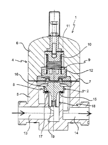
Figure 1 shows a pressure retention valve 1 according to the
invention with a first embodiment of the associated shut-off body or valve
piston 2. The pressure retention valve 1 further has a housing 4 having a
lower housing portion 5 and an upper housing portion 6. In this case the
upper housing portion 6 and the lower housing portion 5 are connected
CA 02766003 2011-12-19
7
together in such a way that clamped between them is a separating
diaphragm 7 subdividing the housing 4 into a fluid-conveying portion 8 and
a fluid-free portion 9.
A coil spring 10 is arranged as a spring element in the fluid-free
portion 9 without the influences of the possibly attacking fluid to be
conveyed. The coil spring 10 is supported at the housing side against an
adjustable support 11 and at its free end presses against a ram 12 guided
movably in the upper housing portion 6. The ram 12 in turn transmits the
spring force of the spring 10 to the valve piston 2 by way of the separating
diaphragm 7.
An inlet passage 13 and an outlet passage 14 through which the fluid
to be conveyed flows are arranged in the fluid-conveying portion 8 of the
housing 4. A housing-side valve seat 15 having a sealing surface 16
defines the transition between the inlet passage 13 and the outlet passage
14, that is to say the end of the inlet passage 13 and the start of the outlet
passage 14.
The spring force of the spring 10 urges the valve piston 2 by way of
the ram 12 and the separating diaphragm 7 with its sealing surface 17
against the valve seat 15 of the housing 4. If the force exerted by the fluid
applied to the valve piston in the inlet passage 13 exceeds the spring force
of the spring 10 the valve is opened.
Above the valve seat 15, that is to say in the outlet passage 14 of
the valve 1, the valve piston 2 shown in Figure 1 does not have a guide but
has a guide portion 18 extending into the inlet passage 13. In that region
the inlet passage 13 is in the form of a guide bush 19 in which the guide
portion 18 is movably guided.
The details of the valve piston 2 are shown more clearly in Figures 2
and 3, a sectional view and a three-dimensional view of the piston
respectively. In the illustrated embodiment the guide portion 18 comprises
eight guide vanes 20 which extends substantially radially. Assuming that
the valve piston 2 is of a cylindrical basic shape the guide vanes 20 extend
along the radius of the cylinder and are spaced from each other in the
peripheral direction. In that way formed between the guide vanes 20 are
CA 02766003 2016-09-28
8
flow passages 21 through which the fluid conveyed in the inlet passage 13
flows substantially parallel to the axis of the cylindrical configuration of
the
guide bush 19.
The outer end faces 22 of the guide vanes 20 are disposed on a circle
of constant radius around the cylinder axis 23 of the piston. In this case
the radius on which the outer end faces 22 of the guide vanes 20 are
disposed is somewhat smaller than the inside radius of the guide bush 19.
That ensures stable lateral guidance for the valve piston 2 in the guide
bush 19 of the inlet passage 13. No fouling can be deposited in the gap
between the end faces 22 of the guide vanes 20 and the bush 19 due to a
through-flow of fluid, which occurs regularly in operation, through the
region of the guide bush 19.
The guide vanes 20 extend as far as the sealing surface 17 of the
valve piston 2 so that, when the valve is opened, that is to say when the
valve piston 2 is pulled a distance out of the bush 19, the fluid to be
conveyed can flow through the flow passages 21 between the sealing
surfaces 16, 17 of the valve seat 15 and of the valve piston 2 respectively
and thus reaches the outlet passage 14 of the valve 1.
In the illustrated embodiment the housing 4 and the valve piston are
made from polyvinylidene fluoride (PVDF) which has extremely good
chemical resistance. To ensure a good and low-wear seal in respect of the
two mutually meeting sealing surfaces 16, 17 of the piston 2 and the valve
seat 15 the sealing surface 17 of the valve piston 2 is formed by a sealing
ring 24. The sealing ring 24 comprises an elastic core of a fluoroelastomer,
here VitonTM, and a chemically resistant sheath of PTFE. The sealing ring
24 is screwed on the body of the valve piston 2 by means of a cap nut 25.
In operation of the valve 1 a fluid is generally present under pressure
in the outlet passage 14. The forces related to the pressure of the fluid act
on all surfaces of the outlet passage, that is to say also on the surfaces of
the valve piston 2 and the surface of the separating diaphragm 7. The
forces of the fluid that act on the separating diaphragm 7 acts substantially
in opposite relationship to the spring force of the coil spring 10 and reduce
its effective spring force. In contrast the forces acting at those surfaces 27
= CA 02766003 2011-12-19
9
of the valve piston 2, which are disposed substantially perpendicularly to
the axis of symmetry 23 of the valve piston or have components in that
direction act in the direction of the spring force of the spring element 10.
In the illustrated embodiment therefore the corresponding surfaces 27 of
the valve piston 2 and the surfaces of the separating diaphragm 7, that are
acted upon with fluid, are so selected that the forces acting thereon in
directions parallel to the axis of symmetry 23 precisely compensate for
each other. The pressure retention valve 1 is therefore compensated
almost free from the action of back pressure or hydrostatically. The force
with which the valve piston 2 is pressed against the valve seat 5 depends
substantially only on the adjustable spring force of the coil spring 10.
Figures 4 and 5 show an alternative embodiment of the valve piston
2'. It could replace the valve piston 2 of the pressure retention valve 1 in
Figure 1 without further modification. Instead of the guide vanes 20 the
valve piston 2' in Figures 4 and 5 has a hollow-cylindrical portion 30' as the
guide portion. The fluid can flow through the free internal space 31' of the
guide portion 30'. As before the outside radius of the guide portion 30' is
such that a small annular gap is formed between the outside wall 32' of the
guide portion 30' and the guide bush 19.
At its upper end towards the sealing surface the hollow guide
cylinder 30' has four orifices 33' through which the fluid flows between the
sealing surfaces 16, 17 and thus passes into the outlet passage 14. The
other components of the valve piston 2' are of a similar design
configuration to the first embodiment of the valve piston 2 in Figures 1 to 3
and are therefore denoted by the same references in Figures 4 and 5 as in
Figures 1 to 3.
Both embodiments of the valve pistons 2, 2' are of an overall length
for the guide portion 18 and 30' respectively, measured from the sealing
surface 17 to the lower edge 26 and 34' respectively, which is just so long
that, when the valve is completely opened, only a maximum of 50 Wo of the
overall length of the guide portion 18 or 30' is pulled out of the guide bush
19 of the housing 4. That avoids tilting of the valve pistons 2, 2' and
ensures trouble-free operation of the valve 1.
CA 02766003 2011-12-19
In both embodiments in Figures 1 to 3 and Figures 4 and 5 provided
at the upper end of the valve piston 2' is a recess 28 as a receiving means
for the ram 12. The ram 12 is in engagement by way of the separating
diaphragm 7 with that receiving means in the piston 2, 2'. In alternative
5 embodiments however the ram can be screwed to the piston or connected
thereto in some other fashion mechanically.
Figures 6a) and b) show sectional views through an alternative
embodiment of a shut-off body or valve piston 2" according to the
invention. The valve piston shown in Figures 6a) and b) substantially
10 corresponds in its basic structure to the valve piston 2 as shown in
Figures
1 to 3. The valve piston 2 of Figure 1 could be replaced by the valve piston
2" of Figures 6a) and b) without limitation. Figure 6b) shows a view on an
enlarged scale of the portion A in Figure 6a). In comparison with the valve
piston 2 of Figures 1 to 3, a two-part structure for the valve piston or shut-
off body 2 and sealing ring 24 was dispensed with. Instead three sealing
ridges 35", 36" and 37" are injected into the edge of the piston, that forms
the sealing surface of the valve piston 2". In addition the valve piston 2" is
made from a PVDF material which is softer than the housing 4. The three
sealing ridges 35", 36", 37" come into engagement with the sealing surface
16 of the valve seat 15 of the valve housing 4 and provide effective sealing
integrity. The described structure makes it possible to dispense with the
sealing ring 24 and the cap nut 25 and nonetheless to achieve good valve
sealing integrity.
Figure 7 shows a sectional view through an embodiment of a
pressure retention valve 1" according to the invention with diaphragm
rupture signalling. Fitted in the pressure retention valve 1" is a shut-off
body as is shown in Figure 6a) and 6b). The housing 4" is of a similar
structure to the housing 4 of the valve in Figure 1. In addition however it
has a motion sensor 38" which detects the edge region of the separating
diaphragm 7". The separating diaphragm 7" is of a structure as is
described in EP 1 384 891 B1 for the diaphragm of a diaphragm pump.
The security diaphragm 7" used in the embodiment in Figure 7
comprises two diaphragm layers which are arranged in mutually
CA 02766003 2011-12-19
11
superposed relationship, wherein those diaphragm layers are connected
sealingly to each other to prevent an ingress of liquid and/or gas at all edge
regions at which liquid or gas could penetrate between the diaphragm
layers. The mutually superposed diaphragm layers are thus liquid-tightly
and gas-tightly connected together at least at their peripheral edge and, if
present, at the through openings in the clamping region and in the centre
at the ram 12. The other mutually facing surfaces of the mutually
superposed diaphragm layers bear against each other without a fixed
connection.
Upon damage to one of the mutually superposed diaphragm layers
during operation fluid to be conveyed through the valve penetrates into the
intermediate space between the mutually superposed diaphragm layers
whereby the pressure within that intermediate space is increased from
atmospheric or sub-atmospheric pressure to the pressure in the hydraulic
fluid or fluid being conveyed. Because the mutually superposed diaphragm
layers are not fixedly connected together over their full area the pressure
or penetrating fluid can spread between the diaphragm layers as far as the
sensor region of the diaphragm. The portion of the sensor region of the
diaphragm 7", where the pressure sensor 38" is in engagement therewith,
is of such a nature that in that portion the diaphragm layers oppose less
resistance to the increased pressure and deform more easily than the
diaphragm layers in the other portions of the diaphragm. In the event of
diaphragm rupture and an increase in pressure that this entails between
the diaphragm layers the portion of the sensor region is urged apart with
an increase in the spacing between the mutually opposite surfaces of
diaphragm layers. That is detected by the pressure sensor 38".
= CA 02766003 2011-12-19
12
List of references
1, 1" pressure retention valve
2, 2', 2" valve piston
4 housing
5 lower housing portion
6 upper housing portion
7, 7" separating diaphragm
8 fluid-conveying portion
9 fluid-free portion
10 coil spring
11 support
12 ram
13 inlet passage
14 outlet passage
15 valve seat
16, 17 sealing surface
18 guide portion
19 guide bush
guide vane
20 21 flow passage
22 end face
23 cylinder axis of the valve piston 2
24 sealing ring
cap nut
25 26 lower edge of the guide portion 18
27 surface of the piston
28 recess
30' hollow-cylindrical guide portion
31' inside wall of the guide portion
32' outside wall
33' orifice
34' lower edge of the guide portion 30'
35",36",37" sealing ridge
CA 02766003 2011-12-19
13
38" pressure sensor