Note: Descriptions are shown in the official language in which they were submitted.
CA 02766059 2011-12-19
WO 2010/146444 PCT/IB2010/001450
GEAR SET FOR DIFFERENTIAL
CROSS REFERENCE TO RELATED APPLICATIONS
[0001) This application claims the benefit of United States provisional
application no.
61/187,764, filed 17 June 2009, which is hereby incorporated by reference as
though fully set
forth herein.
TECHNICAL FIELD
[0002] The present invention relates to a differential including a first gear
comprising a
helical face gear, a second gear comprising a helical pinion configured to be
in meshing
engagement with the helical face gear, a pinion housing configured to house
the helical pinion,
and a support member configured to support the helical pinion.
BACKGROUND
[0003] Helical face gears for use in differentials are known in the art, as
set forth for
example, in U.S. Pat. Nos. 3,253,483 and 4,791,832. However, the incorporation
of helical face
gears into differentials has not been commonly utilized because of, for
example, challenges with
respect to the strength of the gears, the expense in manufacturing gear
components with
acceptable tolerances, and the difficulty in ensuring equal torque sharing
among the gear
components.
[0004] In a differential including a helical face gear, a helical pinion, and
a pinion
housing, the differential may be configured to split torque among multiple
helical pinions that
may be disposed within the pinion housing. The pinion housing may comprise a
generally
annular ring having at least one aperture extending radially inwardly from an
outer radial surface
of the pinion housing. Each aperture may comprise a blind aperture that is
closed by a wall
defining an inner radial surface of the pinion housing. A helical pinion may
be disposed in each
blind aperture. Each helical pinion may include a protrusion at one end of the
helical pinion that
is designed for the purpose of piloting or guiding the pinion within the
pinion housing. The
1
CONFIRMATION COPY
CA 02766059 2011-12-19
WO 2010/146444 PCT/IB2010/001450
protrusion may extend in the direction along the longitudinal axis of the
helical pinion. The
protrusion may be smaller in diameter than the diameter of the helical pinion.
The small
diameter of the protrusion may result in relatively poor piloting of the
helical pinion. The end of
the helical pinion that includes the protrusion may be in contact with the
wall of the pinion
housing that defines an inner radial surface of the pinion housing. Due to
friction between the
contacting surfaces of the end of the helical pinion and the pinion housing,
heat maybe
generated. The heat exchange between the components of the differential may be
poor due to the
thin wall of the pinion housing at the area of contact with the helical
pinion. In addition, the gear
components may encounter errors caused by the manufacturing of gear
components, the
assembly of the differential, and/or the deformation of gear components under
an operating load,
all of which may be unavoidable and may cause unequal torque sharing among the
pinions of a
differential. When there is unequal torque sharing among the pinions of a
differential, this may
result in low torque capacity. In addition, the use of a blind aperture may
result in more difficult
manufacturing of the pinion housing. Because the longitudinal axis of the
blind aperture may
need to be aligned with the longitudinal axis of the helical pinion itself as
well as the longitudinal
axis of the protrusion on the helical pinion, the tolerances for the pinion
housing and the helical
pinion is very tight, further complicating manufacturing of the differential.
[0005] It may be advantageous to improve piloting of the helical pinion in the
pinion
housing and to optimize torque sharing among multiple helical pinions that
maybe disposed in
the pinion housing, both of which may result in significantly higher torque
capacity of the
differential. It may also be advantageous to improve the conditions of heat
exchange in the areas
of the differential where friction is generated because of the contacting
surfaces of the helical
pinion and the pinion housing. In addition, it may be advantageous to improve
the
manufacturability of the differential without requiring costly changes in
manufacturing methods
to increase accuracy for manufacturing of helical pinions and the pinion
housing that may not be
commercially viable in the high volume production of differential with gear
sets with split
torque.
2
CA 02766059 2011-12-19
WO 2010/146444 PCT/IB2010/001450
SUMMARY
[0006] A differential may include a side gear comprising a helical face gear;
a helical
pinion configured for meshing engagement with the side gear; a pinion housing
configured to
house the helical pinion; and a first support member configured to support the
helical pinion.
The side gear may rotate around a differential axis. The helical pinion may
have a first end and a
second end opposing the first end. The pinion housing may comprise a generally
annular ring
and may include: an outer radial surface; an inner radial surface; and an
aperture extending
radially inwardly from the outer radial surface. The first support member may
be disposed
radially inwardly relative to the inner radial surface of the pinion housing.
In some
embodiments, the differential may further include a second support member
configured to
support the helical pinion. The second support member may be disposed radially
outwardly
relative to the outer radial. surface of the pinion housing.
[0007] A differential may include a side gear comprising a helical face gear;
a helical
pinion configured for meshing engagement with the side gear; a pinion housing
configured to
house the helical pinion; a first support member configured, to support the
helical pinion; and a
second support member configured to support the helical pinion. The side gear
may rotate
around a differential axis. The helical pinion may have a first end and a
second end opposing the
first end. The he pinion housing may comprise a generally annular ring and may
include: an
outer radial surface; an inner radial surface; and an aperture extending
radially inwardly from the
outer radial surface through the inner radial surface so that the aperture is
open at both a first end
of the aperture and a second end of the aperture. The second end of the
aperture may oppose the
first end of the aperture. The first support member may engage the first end
of the helical pinion
and may be disposed radially inwardly relative to the inner radial surface of
the pinion housing.
The second support member may engage the second end of the helical pinion and
maybe
disposed radially outwardly relative to the outer radial surface of the pinion
housing.
3
CA 02766059 2011-12-19
WO 2010/146444 PCT/IB2010/001450
BRIEF DESCRIPTION OF THE DRAWINGS
[0008] Embodiments offihe invention will now be described, by way of example,
with
reference to the accompanying drawings, wherein:
[0009] FIG. 1 is a side cross-sectional view of a differential in accordance
with an
embodiment of the invention.
[00010] FIG. 2 is a side cross-sectional view of a differential in accordance
with an
embodiment of the invention.
[00011] FIG. 3 is a front cross-sectional view of the differential of FIG. 2.
[00012] FIG. 4 is a partial front cross-sectional view of the differential of
FIG. 2.
[00013] FIG. 5 is a schematic drawing of the axial displacement of at least
one helical
pinion of the differential of FIG. 4 in the case of zero manufacturing
deviations.
[00014] FIG. 6 is a schematic drawing of the axial displacement of at least
one helical
pinion of the differential of FIG. 4 in the case of at least some
manufacturing deviations.
[00015] FIG. 7 is a partial front cross-sectional view of the differential of
FIG. 2.
[00016] FIG. 8 is a schematic drawing of the axial displacement of at least
one helical
pinion of the differential of FIG. 7 in the case of zero manufacturing
deviations.
[00017] FIG. 9 is a schematic drawing of the axial displacement of at least
one helical
pinion of the differential of FIG. 7 in the case of at least some
manufacturing deviations.
[00018] FIG. 10 is a side cross-sectional view of a differential in accordance
with an
embodiment of the invention.
4
CA 02766059 2011-12-19
WO 2010/146444 PCT/IB2010/001450
[00019] FIG. 11 is a side cross-sectional view of a differential in accordance
with an
embodiment of the invention.
DETAILED DESCRIPTION
[00020] Reference will now be made in detail to embodiments of the present
invention,
examples of which are described herein and illustrated in the accompanying
drawings. While the
invention will be described in conjunction with embodiments, it will be
understood that they are
not intended to limit the invention to these embodiments. On the contrary, the
invention is
intended to cover alternatives, modifications and equivalents, which may be
included within the
spirit and scope of the invention as embodied by the appended claims.
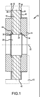
[00021] FIG. 1 generally illustrates an embodiment of differential 10 shown in
accordance with teachings of the present invention. Differential 10 may
comprise a differential
case 12, a side gear 14, a helical pinion 16, pinion housing 18, and a first
support member 20 in
accordance with an embodiment of the invention. Differential case 12 may be
conventional in
the art and may be provided to house side gear 14, helical pinion 16, pinion
housing 18, and first
support member 20, as well any number of other components of the differential
10.
[00022] Side gear 14 may comprise a helical face gear. Accordingly, side gear
14 may
include a number of helical teeth.. The number of helical teeth and the
geometry of the tooth
flank of the helical teeth of the side gear 14 may vary in accordance with
various embodiments
of the invention. The use of forging technology in place of machine-cutting
technology for the
side gears 14 may significantly improve the strength of side gears 14.
Accordingly, the helical
face gears comprising the side gears 14 may be robust and well-supported. The
use of high
strength helical face gears may allow for higher torque application and
provide a wider range of
torque bias ratio. Side gear 14 may rotate around a differential axis 22. A
first and second side
gear 14 maybe disposed on opposing sides of the pinion housing 18 in
accordance with an
embodiment of the invention. Each side gear 14 may include an annular hub
portion (not shown)
with an inner radial surface that includes a plurality of splines. The annular
hub portion may be
configured to receive an axle shaft (not shown) of a motor vehicle such that
the axle shafts may
connect to side gears 14 through a splined interconnection.
CA 02766059 2011-12-19
WO 2010/146444 PCT/IB2010/001450
[00023] Helical pinion 16 may be configured for meshing engagement with the
side gear
14. Helical pinion 16 may have a first end 24 and a second end 26. The second
end 26 may
oppose the first end 24. Helical pinion 16 may include a number of helical
teeth. The number of
helical teeth and the geometry of the tooth flank of the helical teeth of
helical pinion 16 may vary
in accordance with various embodiments of the invention. The helical pinion 16
may be
generally cylindrical in accordance with an embodiment of the invention,
although the shape of
the helical pinion 16 may vary in accordance with various embodiments of the
invention. There
may be a plurality of pinions 16 in some embodiments of the invention. The
number of the
pinions 16 in the differential 10 may vary. However, there may generally be at
least two pinions
16. The number of pinions 16 may be about three or four in an embodiment,
although greater or
fewer pinions 16 may be used in other embodiments.
[00024] Pinion housing 18 may be configured to house and/or locate helical
pinion 16. In
particular, the pinion housing 18 may be configured to house and/or locate the
helical pinion 16
to be in operative or meshing engagement with side gear 14. In accordance with
an embodiment
of the invention, pinion housing 18 may be configured to house and/or locate
multiple helical
pinions 16. The helical pinions 16 may be circumferentially spaced around the
circumference of
the pinion housing 18. Pinion housing 18 may be made from one piece of
material (e.g.,
comprise a unitary, integral, and/or monolithic structure) in accordance with
an embodiment of
the invention. Pinion housing 18 may be generally ring shaped in accordance
with an
embodiment of the invention. In particular, pinion housing 18 may comprise a
generally annular
ring. Pinion housing 18 may include an outer radial surface 28 and an inner
radial surface 30.
The outer radial surface 28 may extend circumferentially around the pinion
housing 18. Pinion
housing 18 may also include an aperture 32. In accordance with an embodiment
of the
invention, pinion housing 18 may include a plurality of apertures 32. For
example only, and
without limitation, there may be approximately three or four apertures 32
extending through the
pinion housing 18. Although three or four apertures 32 are mentioned in
detail, there may be
fewer or more apertures 32 in other embodiments of the invention. The
apertures 32 may be
equiangularly spaced around the circumference of the pinion housing 18.
Although the apertures
32 are described as being equiangularly spaced around the circumference of the
pinion housing
18, the apertures 32 may be spaced in any alternate arrangements and/or
configurations in other
embodiments of the invention.
6
CA 02766059 2011-12-19
WO 2010/146444 PCT/IB2010/001450
[00025] The aperture 32 may have an axis that extends` substantially radially
outwardly
from the approximate center of the pinion housing '18. The aperture 32 may
extend radially
inwardly from the'outer radial surface 28. In accordance with an embodiment of
the invention,
the aperture 32 may extend from the outer radial surface 28 of the pinion
housing 18 through the
inner radial surface 30 of the pinion housing 18. Accordingly, the aperture 32
may be open both
at a first end 34 of the aperture 32 and a second end 36 of the aperture 32.
The first end 34 of the
aperture 32 may oppose the second end 36 of the aperture 32. By utilizing
apertures 32 that may
be machined through the whole body of the pinion housing 18, rather than
comprising a blind
aperture, the manufacturing of the pinion housing 18 and the machining of the
apertures 32 may
be less complex. For example, apertures 32 may be machined in a single set up,
which may
eliminate a significant source of manufacturing errors. Helical pinion 16 may
be disposed in the
aperture 32. The absence of a protrusion on an end of the helical pinion 16,
as well as the
elimination of a source of manufacturing errors by machining in a single set
up, may allow for
reliable and correct piloting of the helical pinion within aperture 32.
Correct piloting of the
helical pinions 16 is critical for proper operation of the differential 10.
The number of helical
pinions 16 may generally correspond to the number of apertures 32 in the
pinion housing 18,
although fewer pinions 16 in relation to the number of apertures 32 may be
used in embodiments
of the invention. In these embodiments of the invention, at least one or more
of the apertures 32
may remain open. The size of pinions 16 may also vary, but may generally be
sized so as to fit
operatively within the apertures 32 of the pinion housing 18 so as to allow
the pinions 16 to be
free to rotate within apertures 32.
[00026] The pinion housing 18 may further comprise a first face 38 and a
second face 40.
The first face 38 may oppose the second face 40. The pinion housing 18 may
further include a
channel 42 extending from the first face 38 to the second face 40 of the
generally annular ring of
the pinion housing 18. The channel 42 may be substantially radially aligned
with the aperture
32. Further, the number of channels 42 may generally correspond to the number
of apertures 32
in the pinion housing 18, although fewer or more channels 42 than the number
of apertures 32
may be used in embodiments of the invention. The helical face of each side
gear 14 may face
pinion housing 18. The side gears 14 may be configured to be in operative or
meshing
engagement with the pinions 16. In particular, the helical teeth of the side
gears 14 may be in an
operative, or meshing, engagement with the helical teeth of the pinions 16.
Both the helical teeth
7
CA 02766059 2011-12-19
WO 2010/146444 PCT/IB2010/001450
of the side gears 14 and the helical teeth of the pinions 16 may extend into
channels 42 in the
pinion housing 18. With a configured meshing engagement between the pinions 16
and the side
gears 14, the side gears 14 may be forced to turn about their axis (i.e.,
differential axis 22). The
side gears 14 may be configured to transmit torque from the pinions 16 to an
output (e.g., axle
shafts of a motor vehicle). Because the output (e.g., axles shafts) are
grounded and coupled to
the side gears 14, a motor vehicle incorporating the differential 10 may move.
When the side
gears 14 rotate at different speeds by grounding through the output (e.g.,
axle shafts), the pinions
16 may rotate within the pinion housing 18 and in mesh with the side gears 14
to compensate.
[00027] First support member 20 may be configured to support the helical
pinion 16. In
particular, the first support member 20 may be configured to restrain the
helical pinions 16 from
axial movement. The helical pinions 16 may generally be axially trapped
between the first
support member 20 and an inner surface of the differential case 12 in
accordance with an
embodiment of the invention as generally illustrated in FIG. 1. The pinion
housing 18 may exert
pressure on the helical pinions 16 to move them around and/or about the
differential axis 22 (i.e.,
an axial center line of the side gears 14). First support member 20 may be
disposed radially
inwardly relative to the inner radial surface 30 of the pinion housing 18.
Accordingly, first
support member 20 may be considered an inner support for helical pinions 16.
First support
member 20 may be generally round in shape. First support member 20 may be a
solid cylindrical
element in accordance with an embodiment of the invention as generally
illustrated in FIG. 1.
First support member 20 may include a central bore in accordance with other
embodiments of
the invention. First support member 20 may include an outer surface 44 that
extends
circumferentially around the inner radial surface 30 of the pinion housing 18,
such that the first
support member 20 faces the end 34 of each of the apertures 32 of pinion
housing 18. In
accordance with an embodiment of the invention as generally illustrated in
FIG. 1, first support
member 20 of differential 10 may engage the inner radial surface 30 of the
pinion housing 18. In
particular, the outer surface 44 of the first support member 20 may engage the
inner radial
surface 30 of the pinion housing 18. In other words, the first support member
20 may only be
configured to rotate about its axis and is not capable of floating in relation
to the pinion housing
18. In the embodiment generally illustrated in FIG. 1, first support member 20
of differential 10
may also engage first end 24 of helical pinion 16. In particular, the outer
surface 44 of the first
support member 20 may engage first end 24 of helical pinion 16. Because of the
large surface
8
CA 02766059 2011-12-19
WO 2010/146444 PCT/IB2010/001450
area of the first support member 20 that is contacting the first end 24 of the
helical pinion 16,
heat exchange between the components of the differential may be significantly
improved.
[00028] In accordance with another embodiment of the invention as generally
illustrated
in FIG. 2, the differential 110 may be substantially identical to the
embodiment generally
illustrated in FIG. 1 except for modification to the first support member 120
and the inclusion of
a second support member 46. In accordance with the embodiment of the invention
as generally
illustrated in FIG. 2, the first support member 120 of differential 110 may be
modified so as to
not engage the inner radial surface 30 of the pinion housing 18. However, the
first support
.member 120 of differential 110 may still engage first end 24 of helical
pinion 16. In particular,
the outer surface 144 of the first support member 120 may engage first end 24
of helical pinion
16. In this embodiment, the first support member 120 does not engage the
pinion housing 18 and
may be capable of floating in relation to the pinion housing 18. In this
embodiment, equal torque
sharing among all of the helical pinions 16 may be possible. First support
member 120 may
comprise a solid cylindrical element in accordance with an embodiment of the
invention. First
support member 120 may include a central bore 45 in accordance with other
embodiments of the
invention. The central bore 45 may be configured to improve serviceability of
the differential
110. Any of differentials 10, 110, 210, 310 as described herein may utilize a
first support
member 20, 120, 220, 320 with a central bore 45 or comprising a solid
cylindrical element.
[00029] In accordance with the embodiment of the invention as generally
illustrated in
FIGS. 2-3, the differential 110 further comprises a second support member 46.
Second support
member 46 may also be configured to support the helical pinion 16. In
particular, the second
support member 46 may be configured to restrain the helical pinions 16 from
axial movement.
The helical pinions 16 may generally be axially trapped between the first
support member 120
and the second support member 46 in accordance with an embodiment of the
invention. Second
support member 46 may be disposed radially outwardly relative to the outer
radial surface 28 of
the pinion housing 18. Accordingly, second support member 46 may be considered
an outer
support for helical pinions 16. Second support member 46 may be generally
round in shape.
Second support member 46 may include an outer surface 48 that extends
circumferentially
around an inner radial surface of the differential case 12.. Second support
member 46 may also
include an inner surface 50 that extends circumferentially around the outer
radial surface 28 of
9
CA 02766059 2011-12-19
WO 2010/146444 PCT/IB2010/001450
the pinion housing 18, such that the second support member 46 faces the end 36
of each of the
apertures 32 of pinion housing 18. In accordance with an embodiment of the
invention, the
second support member 46 of differential 110 may not engage the outer radial
surface 28 of the
pinion housing 18. However, the second support member 46 may engage the
helical pinion 16.
In particular, the second support member 46 may engage the second end 26 of
the helical pinion
16. In this embodiment, the second support member 46 does not engage the
pinion housing 18
and may be capable of floating in relation to the pinion housing 18. In this
embodiment, equal
torque sharing among all of the helical pinions 16 maybe possible.
[000301 In connection with a differential 110 that may include four or more
helical
pinions 16, the first support member 120 and the second support member 46 may
comprise a
flexible material. The flexible material may be capable of elastic deformation
in accordance
with an embodiment. The use of a flexible material may allow the first and
second support
members 120, 46 to function like a leaf spring. Due to manufacturing errors,
the helical pinions
16 may not be loaded in their axial direction equally. Those helical pinions
16 that are more
heavily loaded may elastically deform one or both of the first and second
supports 120, 46:
Elastic deformation of one or both of the first and second supports 120, 46
may allow for
absorption of the negative impact of manufacturing errors onto the torque
performance of the
differential 110. Even if the first and second supports 120, 46 comprise a
flexible material, the
stiffness and rigidity of the first and second supports 120, 46 is large
enough to withhold the
functional loads placed on the first and second supports 120, 46. However, the
stiffness and
rigidity of the first and second supports 120, 46 is small enough to allow for
elastic deformation
to enable the load to be shared substantially evenly among all of the helical
pinions 16. Steel
may be used as a flexible material for the first support member 120 and the
second support
member 46 in accordance with an embodiment of the invention. Although steel is
mentioned in
detail, any number of other flexible materials could.be used in accordance
with other
embodiments of the invention. Although the use of flexible material for
support members 120,
46 is described in connection with a differential 110 that has four or more
helical pinions 16, one
or both of support members 120, 46 may comprise a flexible material in
accordance with any
number of other embodiments of the invention which has fewer helical pinions
16. Moreover,
although the use of flexible material is described only for support members
120, 46 in connection
with differential 110, the use of flexible material may be used in connection
with the support
CA 02766059 2011-12-19
WO 2010/146444 PCT/IB2010/001450
members (e.g., first support member 20) of any other embodiment of the
invention described
herein.
[00031] Referring now to FIG. 3, a front cross-sectional view of differential
110 is
generally illustrated. Differential 110 may comprise about eight helical
pinions 16 in accordance
with the embodiment as generally illustrated. Although eight pinions are
mentioned in detail, the
differential 110 may include fewer or more pinions in accordance with other
embodiments of the
invention. The helical pinions 16 may interact with the first support member
120 and with the
second support member 46. The first support member 120 may include a center-
line CL., pl, and
the second support member 46 may include a center line CLup2. Under axial
thrust exerted by
the helical pinions 16 and the side gear 14, the helical pinions 16 may be
pushed outwards (i.e.,
radially outwardly substantially along an axis of the helical pinion toward
second support
member 46) or inwards (i.e., radially inwardly substantially along an axis of
the helical pinion
toward first support member 120), depending on whether a vehicle incorporating
differential 110
makes a right turn or a left turn. In an ideal case where there are no
manufacturing
errors/deviations (which is not commercially viable), the axial displacement
of all of the helical
pinions 16 may be about equal in length. This may result in uniform elastic
deformation of the
first and second support members 120, 46. However, in a case where there are
ma nufacturing
errors/deviations, each of the helical pinions 16 maybe displaced a certain
distance substantially
along the axis of the helical pinion, and the axial displacement of each
helical pinion 16 may be
of a different value. Because the first and second support members 120, 46 are
flexible, the axial
thrust on the helical pinions 16 may be about equal to each other. In this
way, substantially even
load sharing among all of the helical pinions 16 may be attained. Because the
first and second
support members 120, 46 may be flexible and may be configured to absorb
manufacturing
deviations by allowing for the axial thrust on the helical pinions 16 to be
about equal to each
other. Accordingly, the differential 110 may be relatively insensitive to
manufacturing
deviations, the helical pinions 16 may share a substantially equal load, and
the power capacity of
the differential 110 may be significantly increased.
[00032] . Referring now to FIG. 4, when a vehicle incorporating differential
110 makes a
left turn, the helical pinions 16. may be loaded outward as schematically
depicted. For the ideal
differential having zero manufacturing errors/deviations (which is not
commercially viable), all
11
CA 02766059 2011-12-19
WO 2010/146444 PCT/IB2010/001450
of the helical pinions 16 may be displaced under the load at an equal
displacement 8 as generally
illustrated in FIG. 5. However, in a case where there are manufacturing
errors/deviations (which
is inevitable), each helical pinion 16 may be displaced at its own axial
displacement 8i as
generally illustrated in FIG. 6, where i = I ... N and N is the total number
of the helical pinions
16.
(00033] Referring now to FIG, 7, when a vehicle incorporating differential 110
makes a
right turn, the helical pinions 16 may be loaded inward as schematically
depicted. For the ideal
differential having zero manufacturing errors/deviations (which is not
commercially viable), all
of the helical pinions 16 may be displaced under the load at an equal
displacement A as generally
illustrated in FIG. 8. However, in a case where there are manufacturing
errors/deviations (which
is inevitable), each helical pinion 16 may be displaced at its own axial
displacement A i as
generally illustrated in FIG. 9, where i = 1 ... N and N is the total number
of the helical pinions
16.
[00034] In accordance with another embodiment of the invention as generally
illustrated
in FIG. 10, the differential 210 may be substantially identical to the
embodiment generally
illustrated in FIG. 2 except for modification to the helical pinion 216 and
the first support
member 220. In particular, the modified helical pinion 216 may have a first
end 224 that has a
substantially spherical shape. The radius of curvature Rsph of the
substantially spherical shape
may be defined by a sphere having a center Osph at the differential axis 22.
The first end 224 of
the helical pinion 216 may be substantially concave in accordance with an
embodiment of the
invention. The modified first support member 220 may include an outer surface
244 that extends
circumferentially around the inner radial surface 30 of the pinion housing 18,
such that the first
support member 220 faces the end 34 of each of the apertures 32 of pinion
housing 18. The
outer surface 244 of the first support member 220 may also have a
substantially spherical shape.
The radius of curvature of the substantially spherical shape may also be
defined by a sphere
having a center Osph at the differential axis 22. The outer surface 244 of the
first support member
220 may be substantially convex in accordance with an embodiment of the
invention. As in
some other embodiments, the first support member 220 of differential 210 may
not engage the
inner radial surface 30 of the pinion housing 18. Instead, the outer surface
244 of the first
support member 220 may engage the first end 224 of helical pinion 216. In
accordance with the
12
CA 02766059 2011-12-19
WO 2010/146444 PCT/IB2010/001450
modified embodiment generally illustrated in FIG. 3, the helical pinion 216
and the first support
member 220 make surface contact, instead of point contact. Surface contact may
allow for a
significant reduction of contact pressure on the interacting surfaces of the
helical pinion 216 and
the first support member 220. The embodiment generally illustrated in FIG. 10
may be used in
cases when manufacturing errors of the differential 210 are negligibly small,
and misalignment
of the spherical surfaces of the first support member 220 and of the first end
224 of helical pinion
216 does not negatively affect the bearing capacity of the spherical contact
of the interacting
surfaces of the helical pinion 216 and the first support member 220.
[00035] In accordance with another embodiment of the invention as generally
illustrated
in FIG. 11, the differential 310 may be substantially identical to the
embodiment generally
illustrated in FIG. 10 except for modification to the first support member
320. The modified first
support member 320 may include an outer surface 344 that extends
circumferentially around the
inner radial surface 30 of the pinion housing 18, such that the first support
member 320 faces the
end 34 of each of the apertures 32 of pinion housing 18. The outer surface 344
of the first
support member 320 may have a substantially spherical shape. However, the
radius of curvature
R,, ,p of the substantially spherical shape of first support member 320 may be
less than the radius
of curvature Rpj, of a sphere having a center OSph at the differential axis
22. The outer surface
344 of the first support member 320 may be substantially convex in accordance
with an
embodiment of the invention. By having the radius of curvature RS,,p of the
first support member
320 be smaller as compared to the radius of curvature Rsph of the sphere
having a center Osph at
the differential axis 22, there may be improved lubrication of the contacting
surfaces of the end
224 of the helical pinion 216 and the outer surface 344 of the first support
member 320. The
improved condition of lubrication may be due to the so-called elasto-
hydrodynamic effect (EHD
effect). In accordance with the elasto-hydrodynamic effect, the opposed
surfaces of the end 224
of the helical pinion 216 and the outer surface 344 of the first support
member 320 may be
separated, but there may be some interaction between asperities on the
opposing surfaces, and
there may be an elastic deformation on the contacting surface enlarging the
load bearing area,
whereby the viscous resistance of the lubricant becomes capable of supporting
the load. One of
ordinary skill in the art may determine a desirable reduction in the radius of
curvature R,,,p of the
substantially spherical shape of first support member 320 as compared to the
radius of curvature
13
CA 02766059 2011-12-19
WO 2010/146444 PCT/IB2010/001450
R,ph of a sphere having a center Osph at the differential axis 22 by locating
and using methods
developed in accordance with the theory of elasto-hydrodynamic lubrication.
[00036] The foregoing descriptions of specific embodiments of the present
invention have
been presented for purposes of illustration and description. They are not
intended to be
exhaustive or to limit the invention to the precise forms disclosed, and
various modifications and
variations are possible in light of the above teaching. The embodiments were
chosen and
described in order to explain the principles of the invention and its
practical application, to
thereby enable others skilled in the art to utilize the invention a nd various
embodiments with
various modifications as are suited to the particular use contemplated. The
invention has been
described in great detail in the foregoing specification, and it is believed
that various alterations
and modifications of the invention will become apparent to those skilled in
the art from a reading
and understanding of the specification. It is intended that all such
alterations and modifications
are included in the invention, insofar as they come within the scope of the
appended claims. It is
intended that the scope of the invention be defined by the claims appended
hereto and their
equivalents.
14