Note: Descriptions are shown in the official language in which they were submitted.
CA 02766196 2016-11-24
1
APPARATUS, METHOD AND COMPUTER PROGRAM FOR CONTROLLING AN ACOUSTIC
SIGNAL
FIELD OF THE INVENTION
Embodiments of the present invention relate to an apparatus, method and
computer program. In
particular, they relate to an apparatus, method and computer program for
controlling an acoustic
output signal provided by an audio output device.
BACKGROUND TO THE INVENTION
Apparatus such as telephones comprise loudspeakers which are positioned
adjacent to a user's
ear during use. The acoustic output signal which is provided by an audio
output device may be
required to meet certain criteria. For example, the maximum amplitude of the
acoustic signal
may be limited to avoid injuring a user or damaging components of the
apparatus. Also the
acoustic output signal of the audio output device may be controlled to provide
a particular
standard of sound quality to a user to enable the user to clearly hear the
acoustic signal.
During use a user may change the way they position an apparatus such as a
telephone relative
to their ear. For example, they may press the telephone more tightly to their
ear when they are in
a noisy environment than when they are in a quiet environment. Also different
users may hold
the apparatus in different ways.
It is useful to ensure that such apparatus give a consistent level of
performance irrespective of
how they are held during use.
BRIEF DESCRIPTION OF VARIOUS EMBODIMENTS OF THE INVENTION
According to various, but not necessarily all, embodiments of the invention
there is provided an
apparatus comprising: a filter configured to filter an electrical input signal
and provide a filtered
electrical input signal to an audio output device; the audio output device
configured to convert the
filtered electrical input signal to an acoustic output signal used to
reproduce sound signals in a
user's ear such that the filter is controlled to filter the electrical input
signal to compensate for
distortion in the acoustic output signal in response to a change in position
of the audio output
device relative to the user's ear where the change in position causes the
distortion in the acoustic
output signal; a microphone configured to monitor the sound signals in the
user's ear to detect
components of the acoustic output signal and provide an electrical output
signal corresponding to
the detected components of the acoustic output signal, wherein the microphone
is positioned in
proximity to the audio output device; and a detector configured to receive the
filtered electrical
CA 02766196 2016-11-24
2
input signal provided to the audio output device as a first input and the
electrical output signal
provided by the microphone as a second input, wherein the detector is
configured to detect a
change in signal power of the electrical output signal provided by the
microphone relative to the
filtered electrical input signal provided to the audio output device and, in
response to the
detection of the change in the signal power, provide a control signal to the
filter to control the
filter to compensate for the detected change in signal power, wherein the
audio output device
and the microphone are configured to be positioned adjacent to the user's ear,
and wherein the
change in the signal power of the electrical output signal provided by the
microphone, relative to
the filtered electrical input signal that is provided to the audio output
device and detected by the
detector, provides a frequency response measurement of a system comprising the
user's ear
and the audio output device used to compensate for the distortion in the
acoustic output signal in
response to the change in position of the audio output device relative to the
user's ear.
In some embodiments of the invention the filtered electrical input signal
provided to the audio
output device and the electrical output signal provided by the microphone
comprise a first
frequency component and a second frequency component and the detector is
configured to
detect a change in signal power of the first frequency component.
In some embodiments of the invention the first frequency component is a low
frequency
component and the second frequency component is a high frequency component.
The apparatus may be for wireless communication. For example the apparatus may
be a mobile
cellular telephone or a wireless earpiece.
In some embodiments of the invention the distortion is caused by a low
frequency band of the
acoustic output signal being affected based on the relative position of the
apparatus audio output
device against the user's ear.
According to various, but not necessarily all, embodiments of the invention
there is provided a
method comprising: receiving a filtered electrical input signal that has been
filtered to
compensate for distortion in an acoustic output signal in response to a change
in position of an
audio output device relative to a user's ear where the change in position
causes the distortion in
the acoustic output signal, wherein the acoustic output signal is used to
reproduce sound signals
in the user's ear, and wherein the filtered electrical input signal is
provided to the audio output
device; receiving an electrical output signal provided by a microphone,
wherein the microphone
is positioned in proximity to the audio output device and monitors the sound
signals in the user's
ear to detect components of the acoustic output signal and provides the
electrical output signal
corresponding to the detected components of the acoustic output signal;
detecting a change in
signal power of the electrical output signal provided by the microphone,
relative to the filtered
CA 02766196 2016-11-24
3
electrical input signal provided to the audio output device; and providing, in
response to the
detection of the change in the signal power, a control signal to a filter to
control the filter to filter
the electrical input signal provided to the audio output device to compensate
for the detected
change in the signal power, wherein the audio output device and the microphone
are positioned
adjacent to the user's ear, and wherein the change in the signal power of the
electrical output
signal provided by the microphone, relative to the filtered electrical input
signal that is provided to
the audio output device, provides a frequency response measurement of an
acoustical system
comprising the user's ear and the audio output device used to compensate for
the distortion in
the acoustic output signal in response to the change in position of the audio
output device
relative to the user's ear.
In some embodiments of the invention the filtered electrical input signal
provided to the audio
output device and the electrical output signal provided by the microphone
comprise a first
frequency component and a second frequency component and the change in the
signal power of
the output signal provided by the microphone corresponds to a change in signal
power of the first
frequency component.
In some embodiments of the invention the first frequency component is a low
frequency
component and the second frequency component is a high frequency component.
In some embodiments of the invention the distortion is caused by a low
frequency band of the
acoustic output signal being affected based on the relative position of the
audio output device
against the user's ear.
According to various, but not necessarily all, embodiments of the invention
there is provided a
non-transitory computer-readable storage medium encoded with instructions
that, when executed
by a processor, perform the method described.
According to various, but not necessarily all, embodiments of the invention
there is provided a
non-transitory computer readable storage medium comprising computer program
instructions
stored therein configured to control an apparatus, the program instructions
enabling, when
loaded into a controller: receiving a filtered electrical input signal that
has been filtered to
compensate for distortion in an acoustic output signal in response to a change
in position of an
audio output device relative to a user's ear where the change in position
causes the distortion in
the acoustic output signal, wherein the acoustic output signal is used to
reproduce sound signals
in the user's ear, and wherein the filtered electrical input signal is
provided to the audio output
device; receiving an electrical output signal provided by a microphone,
wherein the microphone
is positioned in proximity to the audio output device and monitors the sound
signals in the user's
ear to detect components of the acoustic output signal and provides the
electrical output signal
CA 02766196 2016-11-24
-
.
4
corresponding to the detected components of the acoustic output signal;
detecting a change in
signal power of the electrical output signal provided by the microphone
relative to the filtered
electrical input signal provided to the audio output device; and providing, in
response to the
detection of the change in the signal power, a control signal to a filter to
control the filter to filter
the electrical input signal provided to the audio output device to compensate
for the detected
change in the signal power, wherein the audio output device and the microphone
are positioned
adjacent to the user's ear, and wherein the change in the signal power of the
electrical output
signal provided by the microphone, relative to the filtered electrical input
signal that is provided to
the audio output device, provides a frequency response measurement of an
acoustical system
comprising the user's ear and the audio output device used to compensate for
the distortion in
the acoustic output signal in response to the change in position of the audio
output device
relative to the user's ear.
In some embodiments of the invention the distortion is caused by a low
frequency band of the
acoustic output signal being affected based on the relative position of the
audio output device
against the user's ear.
According to various, but not necessarily all, embodiments of the invention
there is provided a
detector comprising: a first physical input port configured to receive a
filtered electrical input
signal provided to an audio output device; a second physical input port
configured to receive an
electrical output signal provided by a microphone, wherein the microphone is
positioned in
proximity to the audio output device and monitors sound signals in a user's
ear to detect
components of an acoustic output signal and provides the electrical output
signal corresponding
to the detected components of the acoustic output signal; and a physical
output port configured
to provide an output signal to a filter which filters the electrical input
signal provided to the audio
output device, wherein the filter is controlled to filter the electrical input
signal to compensate for
distortion in the acoustic output signal in response to a change in position
of the audio output
device relative to the user's ear where the change in position causes the
distortion in the acoustic
output signal, and wherein the acoustic output signal is used to reproduce the
sound signals in
the user's ear, wherein the detector is configured to detect a change in
signal power of the
electrical output signal provided by the microphone relative to the filtered
electrical input signal
provided to the audio output device and, in response to the detection of the
change in the signal
power, provide a control signal to the filter to control the filter to
compensate for the detected
change in the signal power, wherein the audio output device and the microphone
are configured
to be positioned adjacent to the user's ear, and wherein the change in the
signal power of the
electrical output signal provided by the microphone, relative to the filtered
electrical input signal
that is provided to the audio output device, provides a frequency response
measurement of a
system comprising the user's ear and the audio output device used to
compensate for the
CA 02766196 2016-11-24
4a
distortion in the acoustic output signal in response to the change in position
of the audio output
device relative to the user's ear.
In some embodiments of the invention the filtered electrical input signal
provided to the audio
output device and the electrical output signal provided by the microphone
comprise a first
frequency component and a second frequency component and the detector is
configured to
detect a change in signal power of the first frequency component.
In some embodiments of the invention the first frequency component is a low
frequency
component and the second frequency component is a high frequency component.
In some embodiments of the invention the distortion is caused by a low
frequency band of the
acoustic output signal being affected based on the relative position of the
audio output device
against the user's ear.
BRIEF DESCRIPTION OF THE DRAWINGS
For a better understanding of various examples of embodiments of the present
invention
reference will now be made by way of example only to the accompanying drawings
in which:
Fig. 1 schematically illustrates an apparatus according to a first embodiment
of the invention;
Fig. 2 illustrates an apparatus according to embodiments of the invention;
Fig. 3 illustrates a flow chart showing a method according to an embodiment of
the invention;
Fig. 4 illustrates a plot of the magnitude of the frequency response measured
in a user's ear
canal against the frequency;
Fig. 5 illustrates a detector according to an embodiment of the invention;
I anllir CA 02766196 2011-12-20
WO 2011/001010
PCT/F12010/050150
Fig. 6 illustrates an apparatus according to the first embodiment of the
invention in more
detail; and
Fig. 7 illustrates an apparatus according to another embodiment of the
invention.
5 DETAILED DESCRIPTION OF VARIOUS EMBODIMENTS OF THE INVENTION
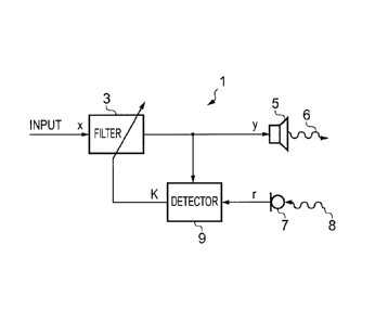
The Figures illustrate an apparatus 1 comprising: a filter 3 configured to
filter an electrical
input signal x and provide a filtered electrical input signal y to an audio
output device 5; an
audio output device 5 configured to convert the filtered electrical input
signal y to an
acoustic output signal 6; a microphone 7 configured to detect an acoustic
signal 8 and
provide an electrical output signal r corresponding to the detected acoustic
signal 8; and a
detector 9 configured to receive the filtered electrical input signal y
provided to the audio
output device 5 as a first input and the electrical output signal r provided
by the microphone
7 as a second input; wherein the detector 7 is configured to detect a change
in the signal
power of the electrical output signal r provided by the microphone 7 relative
to the filtered
electrical input signal y provided to the audio output device 5 and, in
response to the
detection of the change in the signal power, provide a control signal K to the
filter 3 to
control the filter 3 to compensate for the detected change in signal power.
In the following description, unless expressly stated otherwise, the words
"connect" and
"couple" and their derivatives mean operationally connected or operationally
coupled. It is
to be appreciated that any number or combination of intervening components can
exist
including no intervening components.
Fig.1 schematically illustrates an apparatus according to a first embodiment
of the invention.
The apparatus comprises a filter 3, an audio output device 5, a microphone 7
and a detector
9. Only features referred to in the following description are illustrated. It
should, however,
be understood that the apparatus 1 may comprise additional features that are
not illustrated.
The apparatus 1 may be any apparatus which comprises an audio output device 5
which
may be positioned adjacent to a user's ear in use. For example, the apparatus
1 may be a
telephone such as a cellular mobile telephone or an earpiece. The audio output
device 5
may, for example, be a loudspeaker, or other form of audio transducer that
converts an
electrical signal to acoustic pressure waves.
The filter 3 is configured to receive an electrical input signal x and provide
a filtered
electrical output signal y. The electrical input signal x may be received from
an audio
= JINN. CA 02766196 2011-12-20
WO 2011/001010
PCT/FI2010/050150
6
apparatus. The audio apparatus may be any means which produces an audio output
such
as a cellular mobile telephone or an earpiece. The electrical input signal x
may correspond
to speech which is part of a telephone conversation.
The electrical input signal x provided to the filter 3 may comprise a
plurality of different
frequency components. The filter 3 may be configured to filter the electrical
input signal x by
attenuating some of the frequency components. In some embodiments of the
invention the
filter 3 may be configured to attenuate some frequency components and enhance
other
frequency components. The filter 3 may be an equalization filter. For example
the filter 3
may be a shelving filter.
The filter 3 may be configured to filter the electrical input signal x to
enable an acoustic
signal 6, provided by the audio output device 5 in response to the filtered
electrical input
signal y, to fulfill certain criteria. For example it may attenuate certain
frequencies to
prevent the acoustic output signal 8 having a large amplitude which may injure
a user or
damage some of the electrical components of the apparatus 1. The filter 3 may
also
enhance or attenuate certain frequencies to provide an improved sound quality
for the user
of the apparatus 1. The filter is able to produce a desired magnitude response
to the ear
improving the perceived audio quality.
The audio output device 5 is configured to convert the filtered electrical
input signal y to an
acoustic output signal 6. The acoustic output signal 6 may comprise a
plurality of different
frequency components. The plurality of different frequency components may
comprise
frequency components from the audible frequency range. The acoustic output
signal 6 may
comprise a first frequency component and a second frequency component. The
first
frequency component may be a low frequency component, for example, the first
frequency
component may comprise frequencies in the range 0-1.5kHz. The second frequency
component may be a high frequency component, for example, the second frequency
component may comprise frequencies in the range 2.5-4kHz.
In embodiments of the invention where the apparatus 1 is a telephone or
earpiece the
output signal 6 may comprise speech which is part of a telephone conversation.
The microphone 7 is configured to detect the acoustic input signal 8 and
convert this into an
electrical output signal r.
deka. CA 02766196 2011-12-20
WO 2011/001010
PCT/FI2010/050150
7
The microphone 7 may be positioned within the apparatus 1 so that the detected
acoustic
input signal 8 provides a measure of the frequency response of the system
comprising the
apparatus 1 and the user's ear. The detected acoustic input signal 8 may
comprise
components of the acoustic output signal 6 which have been reflected by the
user's ear.
The frequency response may be unique to each user and also to each ear of each
user.
The frequency response may also be dependent on how the apparatus 1 is
positioned
relative to the user's ear. For example the frequency response may depend on
how tightly
the apparatus 1 is pressed next to the user's ear and the amount of leakage
between the
apparatus 1 and the user's ear and the distance between the audio output
device 5 and the
user's eardrum.
The detector 9 is configured to receive the filtered electronic input signal y
as a first input
and the electrical output signal r provided by the microphone 7 as a second
input. The
detector 9 is configured to compare the signal power of the electrical output
signal r
provided by the microphone 7 to the signal power of the filtered electronic
input signal y and
detect a change in the relative signal power. The signal power may be
determined over an
appropriate time interval. For example, the signal power may be calculated
over the duration
of each speech frame. A speech frame is typically 20ms.
The detector 9 is configured to provide the control signal K in response to
the detection of a
change in the relative signal power. A change in the relative signal power may
occur if, for
example, a user changes the position of the apparatus 1 relative to their ear
during use.
This may change the size of the gap between the apparatus 1 and the user's ear
and so
change the amount of leakage of the acoustic output signal 6. This changes the
frequency
response of the system comprising the apparatus 1 and the user's ear.
The detector 9 is coupled to the filter 3 so that the control signal K is
provided to the filter 3.
The control signal K controls the filter 3 to filter the electrical input
signal x to compensate
for the detected change in the relative signal power. The value of the control
signal K may
depend on whether the relative signal power level has increased or decreased.
The
magnitude of the control signal K may depend on the magnitude of the detected
change in
the signal power.
Fig. 2 illustrates an apparatus 1 according to embodiments of the invention.
In the particular
embodiment illustrated in Fig. 2 the apparatus 1 is a cellular mobile
telephone.
CA 02766196 2011-12-20
=
WO 2011/001010
PCT/FI2010/050150
8
The apparatus 1 comprises a housing 25, an audio output device 5 and a
microphone 7.
The electronic components of the apparatus 1 may be contained within the
housing 25. The
housing 25 may be sized and shaped so that it may be held comfortably in a
user's hand.
The audio output device 5 is positioned within the housing 25 so that when the
user holds
the apparatus 1 close to their head the audio output device 5 is positioned
adjacent to their
ear. The audio output device 5 is positioned so that the acoustic output
signal 6 is directed
outwards from the apparatus 1.
The microphone 7 is positioned within the housing 25 in proximity to the audio
output device
5. In the embodiment of the invention illustrated in Fig. 2 the microphone is
positioned
adjacent to the audio output device 5. The microphone 7 is positioned so that
it provides a
measure of the frequency response of the system comprising the apparatus 1 and
the
user's ear. The microphone 7 may be positioned to detect acoustic input
signals which are
1 5 reflected from the user's ear.
In the embodiment illustrated in Fig. 2 the apparatus 1 also comprises a
display 21 and a
keypad 23. The keypad 23 enables a user to make user inputs to control the
apparatus 1.
The display 211s configured to display information to a user. The microphone 7
and the
audio output device 5 are positioned above the display 21 and the keypad 23.
Fig. 3 illustrates a flow chart showing a method which may be carried out by
an apparatus 1
according to embodiments of the invention. Blocks 31, 33, 35 and 37 of the
method may be
carried out by the detector 9. Block 39 may be carried out by the filter 3.
At block 31 the detector 9 receives the filtered electrical input signal y as
a first input. The
filtered electrical input signal y is also provided to the audio output device
5 where it is
converted into the acoustic output signal 6. The filtered electrical input
signal y corresponds
to the electrical input signal x which has been filtered by the filter 3.
As mentioned above the filtered electrical input signal y comprises a
plurality of frequency
components. The plurality of frequency components may comprise a high
frequency band
and a low frequency band. The high frequency band may comprise frequencies in
the
range 2.5-4kHz. The low frequency band may comprise frequencies in the range 0-
1.5kHz.
At block 33 the detector 9 receives the electrical output signal r provided by
the microphone
3. The electrical output signal r corresponds to an acoustic input signal 8
which has been
CA 02766196 2011-12-20
WO 2011/001010 PCT/F12010/050150
9
detected by the microphone 7. The detected input acoustic signal 8 may provide
a measure
of the frequency response of the system comprising the apparatus 1 and the
user's ear.
The detected input acoustic signal 8 may comprise components of the acoustic
output
signal 6 which have been reflected by a user's ear.
The electrical output signal r also comprises a plurality of frequency
components. The
plurality of frequency components may comprise a high frequency band and a low
frequency band. The high frequency band may comprise frequencies in the range
2.5-
4kHz. The low frequency band may comprise frequencies in the range 0-1.5kHz.
At block 35 the detector 9 detects a change in the signal power of the
electrical output signal
r relative to the filtered electrical input signal y. The change in relative
signal power may
arise, for example, if the user changes the way they are holding the
apparatus. For
example, if the user is in a noisy environment they may press the apparatus 1
more tightly
to their ear. This reduces the gap between the apparatus 1 and the user's ear
and so
reduces the amount of leakage of the acoustic signal 6. This changes the
frequency
response of the system comprising the apparatus 1 and the user's ear.
The change in position of the apparatus 1 may affect some frequencies more
than others.
For example the position of the apparatus 1 relative to the user's ear may
affect the low
frequency band more than the high frequency band as illustrated in Fig. 4.
Fig. 4 is an example of a plot of the magnitude of the frequency response
measured in a
user's ear canal against the frequency for a plurality of different forces
being applied to the
apparatus 1. The first plot corresponds to the apparatus 1 being pressed
against the user's
ear with a force of 16N, the second plot corresponds to the apparatus 1 being
pressed
against the user's ear with a force of 10N and the third plot corresponds to
the apparatus 1
being pressed against the user's ear with a force of 4N.
The first plot has the largest frequency response for frequencies in the band
0-1.5kHz and
the third plot has the lowest frequency response for this band. Therefore it
can be seen that
increasing the force applied to the apparatus 1 by pressing the apparatus 1
more closely to
a user's ear will boost the low frequency response of the system.
All three plots have a similar magnitude for frequencies in the range 2.5-
4kHz. Therefore it
can be seen that the changing the force applied to the apparatus does not
effect the
frequency response of the system for the high frequency band very much.
CA 02766196 2011-12-20
WO 2011/001010 PCT/FI2010/050150
As the force applied to the apparatus affects the low frequency band more than
the high
frequency band this may lead to distortion of an acoustic output signal 6.
This may reduce
the sound quality perceived by the user. Where the acoustic output signal 6
comprises
5 speech it may make it difficult for the user to understand the speech.
Referring back to Fig. 3, once the change in signal power has been detected
the detector 9,
at block 37, provides the control signal K to the filter 3. The value of the
control signal K may
depend on whether the relative signal power level has increased or decreased.
For
1 0 example, it may depend on whether the user has increased the force
applied to the
apparatus 1 or decreased the force applied to the apparatus 1. The magnitude
of the
control signal K may depend on the magnitude of the detected change in the
signal power.
This may depend on the amount by which the user has changed the force applied
to the
apparatus 1.
At block 39 the filter 3 receives the control signal K and filters the
electrical input signal
provided to the audio output device 5. The control signal K controls the
filter to compensate
for the detected change in signal power.
Block 35 where the detector 9 detects a change in the signal power of the
electrical output
signal r relative to the signal power of the filtered electrical input signal
y may occur
separately for different frequency bands.
For example, one block 35 may detect a change in the signal power (Pr low) of
the electrical
output signal r in a first lower frequency band relative to the signal power
(Py bõ,) of the
filtered electrical input signal y in the first lower frequency band. The
change may be
determined by, for example, dividing
the signal power (Pr low) of the electrical output signal r in a first lower
frequency band by the
signal power (Py10,) of the filtered electrical input signal y in the first
lower frequency band.
Before the change is determined, the signal power (Pr low) of the electrical
output signal r in a
first lower frequency band may be normalized with respect to the signal power
(Pr high) of the
electrical output signal r in a second higher frequency band. This may be
achieved by
dividing the signal power (Pr low) of the electrical output signal r in the
first lower frequency
band by the signal power (Pr high) of the electrical output signal r in the
second higher
frequency band.
No, CA 02766196 2011-12-20
WO 2011/001010 PCT/FI2010/050150
11
Before the change is determined, the signal power (Py low) of the filtered
electrical input
signal y in the first lower frequency band may be normalized with respect to
the signal
power (Py high) of the filtered electrical input signal y in the second higher
frequency band.
This may be achieved by dividing the signal power (Py low) of the filtered
electrical input
signal y in the first lower frequency band by the signal power (Py high) of
the filtered electrical
input signal yin the second higher frequency band.
In some implementations, a change in signal power may be simultaneously
determined for
multiple different low frequency bands. The same higher frequency band may be
used as a
normalizing reference.
Signals may be divided into different frequency bands before signal power
determination
using for example pass filters. A pass filter is a filter that allows a
selected frequency band
to pass either because it is a band pass filter, a low pass filter or a high
pass filter. In other
implementations, a transformer may be used to convert signals from the time
domain to
spectral bands in the frequency domain.
For example, if the detector 9 has detected an increase in the signal power
for the low
frequency band then the control signal K will control the filter to attenuate
the low frequency
components of the electrical input signal x. The increase in the signal power
for the low
frequency band may occur if the user increases the force with which they are
pressing the
apparatus 1 to their ear. Conversely if the detector 9 has detected a decrease
in the signal
power of the low frequency band then the control signal K will control the
filter 3 to enhance
the low frequency components of the electrical input signal x. The decrease in
the signal
power for the low frequency band may occur if the user decreases the force
with which they
are pressing the apparatus 1 to their ear
The blocks illustrated in Fig. 3 may represent steps in a method and/or
sections of code in
the computer program. The illustration of a particular order to the blocks
does not
necessarily imply that there is a required or preferred order for the blocks
and the order and
arrangement of the block may be varied. Furthermore, it may be possible for
some steps to
be omitted.
Embodiments of the invention therefore provide the advantage that the filter 3
may be
controlled to filter the electrical input signal x to compensate for any
distortion of the
acoustic output signal 6 which may arise as a result of a change in position
of the apparatus
. CA 02766196 2011-12-20
WO 2011/001010
PCT/FI2010/050150
12
1. This enables a good sound quality to be provided to a user irrespective of
the force
applied to the apparatus 1 when they are holding the apparatus 1 next to their
ear.
Also, embodiments of the invention may provide the advantage that they
decrease the
amplitude of the low frequency signals which may prevent injury to a user and
may also
prevent damage to components of the apparatus 1.
Embodiments of the invention detect a change in the position of the apparatus
1 by
detecting a change in the signal power. The signal power calculation is a may
be carried
out quickly. This means that only a small amount of processing power is
required. It also
enables the apparatus 1 to respond quickly to a change in the position of the
apparatus 1 so
that the filter 3 may compensate for the change in position without any
noticeable reduction
in sound quality by the user.
Fig. 5 schematically illustrates a detector 9 according to an embodiment of
the invention in
more detail. The detector 9 comprises a plurality of frequency band filters
41, 43, 45, 47,
means for calculating the signal power 50, means for comparing the relative
signal power 60
and means 77 for providing a control signal K as an output.
The first frequency band filter 41 is a low frequency band filter which is
configured to allow
the low frequency components to pass through but attenuates the high frequency
components. The first frequency band filter 41 is configured to receive the
filtered electronic
input signal y as an input. The filtered electronic input signal y is also
provided to the audio
output device 5 which is not illustrated in Fig. 5.
The first frequency band filter 41 is coupled to first signal power
calculation means 51 so
that the output of the first frequency band filter 41 is provided to the first
signal power
calculation means 51. The signal power calculation means may be configured to
determine
the signal power of an input signal using any suitable method. The first
signal power
calculation means 51 are configured to determine the signal power in the low
frequency
components of the filtered electronic input signal y and provide this an
output signal
The second frequency band filter 43 is a high frequency band filter which is
configured to
allow the high frequency components to pass through but attenuates the low
frequency
components. The second frequency band filter 43 is also configured to receive
the filtered
electronic input signal y as an input.
CA 02766196 2011-12-20
WO 2011/001010 PCT/F12010/050150
13
The second frequency band filter 43 is coupled to second signal power
calculation means
53 so that the output of the second frequency band filter 43 is provided to
the second signal
power calculation means 53. The second signal power calculation means 53 are
configured
to determine the signal power in the high frequency components of the filtered
electrical
input signal y and provide this an output signal Py high.
The output signal Py high of the second power calculation means 53 is provided
to an inverter
61 which inverts the signal Py high to provide 1/ Py high. This is then
multiplied, by the first
multiplier 71, with the output signal Py low of the first signal power
calculation means to
provide R=Py low/ Py high which is the ratio of the signal power in the low
frequency band to
the signal power in the high frequency band for the filtered electronic input
signal y.
The third frequency band filter 45 is also another low frequency band filter
which is
configured to allow the low frequency components to pass through but
attenuates the high
frequency components. The third frequency band filter 45 may be the same as
the first
frequency band filter 41. The third frequency band filter 45 is configured to
receive the
electronic output signal r provided by the microphone 7 as an input.
The third frequency band filter 45 is coupled to third signal power
calculation means 55 so
that the output of the third frequency band filter 45 is provided to the third
signal power
calculation means 55. The third signal power calculation means 55 are
configured to
determine the signal power in the low frequency components of the electronic
output signal r
provided by the microphone 7 and provide this an output signal P
= r low=
The fourth frequency band filter 47 is another high frequency band filter
which is configured
to allow the high frequency components to pass through but attenuates the low
frequency
components. The fourth frequency band filter 47 may be the same as the second
frequency
band filter 42. The second frequency band filter 43 is also configured to
receive the
electronic output signal r provided by the microphone 7 as an input.
The fourth frequency band filter 47 is coupled to fourth signal power
calculation means 57
so that the output of the fourth frequency band filter 47 is provided to the
fourth signal power
calculation means 55. The fourth signal power calculation means 57 are
configured to
determine the signal power in the high frequency components of the electronic
output signal
r provided by the microphone 7 and provide this an output signal P
= r high.
= Il CA 02766196 2011-12-20
WO 2011/001010
PCT/F12010/050150
14
The output signal Pr high of the fourth power calculation means 57 is provided
to an inverter
63 which inverts the signal Pr high to provide 1/ P
= r high- This is then multiplied by the second
multiplier 73, with the output signal Pr low of the third signal power
calculation means to
provide Rr=Pr low/ Pr high which is the ratio of the signal power in the low
frequency band to the
signal power in the high frequency band for the electronic output signal r
provided by the
microphone 7.
The output of the first multiplier 71 is provided to the inverter 65 and
inverted to provide 1/Ry
as an output signal. The output of the inverter 65 is then provided to the
multiplier 75. The
1 0 output of the second multiplier 73 is also provided to the third
multiplier 75. The third
multiplier 75 multiplies the two input signals to provide the ratio Rror.Rr/Ry
as an output
signal. This provides a comparison of the signal power in the electrical
output signal r
provided by the microphone 7 compared to the filtered electrical input signal
y provided to
the audio output device 5.
The ratio Rror=Rr/Ry is converted into decibels by the converter 77 to provide
the control
signal K. The value of the control signal K is therefore determined by the
relative signal
powers of the two input signals r, y provided to the detector 9. If the
relative signal power
changes the detector 9 detects this and the value of K will change
accordingly.
Fig. 6 schematically illustrates an apparatus 1 according to another
embodiment of the
invention. The apparatus 1 comprises a filter 3, an audio output device 5, a
microphone 7
and a detector 9 as described in relation to the embodiment illustrated in
Fig. 1.
The apparatus illustrated in Fig. 6 also comprises a delay line 81. The delay
line 81 is
connected between the filter 3 and the detector 9. The delay line 81 is
configured to
introduce a delay into the filtered electrical input signal y before it is
provided to the detector
9. The delay may be configurable. The delay is used to synchronize the
electrical output
signal r and the filtered electrical input signal y so that they both relate
to the same audio
event. The filtered electrical input signal y for an audio event is delayed so
that the detector
9 compares the electrical output signal r and the filtered electrical input
signal y for the
same audio event.
The detector 9 comprises a plurality of frequency band filters 41, 43, 45, 47,
means for
calculating the signal power 50, means for comparing the relative signal power
60 and
means 77 for providing a control signal K as an output which operate as
described above in
relation to Fig. 5.
CA 02766196 2011-12-20
WO 2011/001010 PCT/FI2010/050150
The detector in Fig. 6 comprises the additional component of a summer 91. The
output
signal K is added to K.-
-onst by the summer 91 to provide Kest as an output signal. K- is
¨ a
constant value which is added to shift the output signal Kest to zero when the
apparatus 1 is
5 held in a standard position.
The detector 9 also comprises a first downsampler 95, and a second downsampler
97. The
downsamplers reduce the sampling rate by a factor N. In the embodiment of the
invention
illustrated in Fig. 6 both of the downsamplers decrease the sampling rate by
the same factor
10 N. The first downsampler 95 is configured to reduce the sampling rate of
the filtered
electrical input signal y before it is provided to the first and second
frequency band filters 41,
43 and the second downsampler 97 is configured to reduce the sampling rate of
the
electrical output signal r provided by the microphone 7 before it is provided
to the third and
fourth frequency band filters 45, 47.
The detector 9 also comprises a high pass filter 87. The high pass filter is
configured to
filter out very low frequency signals which cannot be detected by the
microphone 7. The
high pass filter 87 is coupled to the down sampler 95 and the first and second
frequency
band filters 41, 43 such that after the filtered electrical input signal y has
been downsam pled
it is provided to a high pass filter 87. The output of the high pass filer 84
is provided to the
first and second frequency band filters 41, 43.
The detector 9 also comprises an additional signal power calculation means 59.
The output
of the high pass filer 84 is also provided to the additional signal power
calculation means 59.
The additional signal power calculation means 59 is configured to calculate
the total signal
power of the filtered electrical input signal y to proved Einput as an output
signal.
The output signal Einput is provided to block 93. The output signal Kest is
also provided to
block 93. Block 93 determines whether or not the value of Einput is above a
predetermined
threshold. If E,nput is above a predetermined value then Kest is provided as
the control signal
to the filter 3. If Einput is below a threshold value then Kmem is provided as
the control signal
to the filter 3. Kmem is the last value of Kest which was used and is used to
avoid bias when
the total signal power level is too low.
The apparatus 1 illustrated in Fig. 6 may also comprises a first smoothing
filter 85 and a
second smoothing filter 87. The first smoothing filter 85 and a second
smoothing filter 87
are connected between the detector 9 and the filter 3 to filter the control
signal before it is
CA 02766196 2011-12-20
WO 2011/001010 PCT/F12010/050150
16
provided to the filter 3. In this example, the first smoothing filter 85
smoothes the output of
the detector 9 between frames. In this example, the second smoothing filter 87
smoothes
the output of the detector 9 between samples.
Fig. 7 schematically illustrates an apparatus 1 according to another
embodiment of the
invention 1. The apparatus 1 comprises a filter 3, an audio output device 5
and a
microphone 7 as described in relation to the embodiments illustrated in Figs.
1 and 6.
In Fig. 7 the detector 9 comprises a controller 101 which is configured to
detect a change in
the signal power of the electrical output signal r provided by the microphone
7 relative to the
filtered electrical input signal y provided to the audio output device.
The controller 101 provides means for controlling the filter 3. In some
embodiments of the
invention the controller 101 may also control other functions of the apparatus
1. In the
illustrated embodiment the controller 101 comprises a processor 103 and a
memory 105.
The controller 101 may be implemented using instructions that enable hardware
functionality, for example, by using executable computer program instructions
109 in a
general-purpose or special-purpose processor 103 that may be stored on a
computer
readable storage medium 111 (e.g. disk, memory etc) to be executed by such a
processor
107.
The memory 105 stores a computer program 107 comprising computer program
instructions
109 that control the operation of the filter 3 when loaded into the processor
103. The
computer program instructions 109 provide the logic and routines that enables
the
apparatus 1 to perform the methods illustrated in Fig. 3. The processor 103 by
reading the
memory 105 is able to load and execute the computer program 107.
The computer program instructions 109 may provide computer readable program
means for
enabling receiving a filtered electrical input signal y where the filtered
electrical input signal y
is also provided to an audio output device 5; receiving an electrical output
signal r provided
by a microphone 7; detecting a change in the signal power of the electrical
output signal r
provided by the microphone 7 relative to the filtered electrical input signal
y provided to the
audio output device 5; and providing, in response to the detection of the
change in the
signal power, a control signal K to a filter 3 to control the filter 3 to
filter the electrical input
signal y provided to the audio output device to compensate for the detected
change in signal
power.
CA 02766196 2011-12-20
WO 2011/001010 PCT/F12010/050150
17
The computer program 107 may arrive at the apparatus 1 via any suitable
delivery
mechanism. The delivery mechanism may be, for example, a computer-readable
storage
medium 111, a computer program product, a memory device such as a flash
memory, a
record medium such as a CD-ROM or DVD, an article of manufacture that tangibly
embodies the computer program 107. The delivery mechanism may be a signal
configured
to reliably transfer the computer program 107. The apparatus 1 may propagate
or transmit
the computer program 107 as a computer data signal.
Although the memory 105 is illustrated as a single component it may be
implemented as
one or more separate components some or all of which may be
integrated/removable and/or
may provide permanent/semi-permanent/ dynamic/cached storage.
References to 'computer-readable storage medium', 'computer program product',
'tangibly
embodied computer program' etc. or a 'controller', 'computer', 'processor'
etc. should be
understood to encompass not only computers having different architectures such
as single
/multi- processor architectures and sequential (e.g. Von Neumann)/parallel
architectures but
also specialized circuits such as field-programmable gate arrays (FPGA),
application
specific integration circuits (ASIC), signal processing devices and other
devices. References
to computer program, instructions, code etc. should be understood to encompass
software
for a programmable processor or firmware such as, for example, the
programmable content
of a hardware device whether instructions for a processor, or configuration
settings for a
fixed-function device, gate array or programmable logic device.
The controller 101 is configured to receive the filtered electrical input
signal y as a first input
and the electrical output signal r provided by the microphone 7 as a second
input. The
controller 101 is configured to detect a change in the relative signal power
of the two signals
as described above and provide the control signal K to the filter 3 to control
the filter 3 to
compensate for the detected change in signal power.
Although embodiments of the present invention have been described in the
preceding
paragraphs with reference to various examples, it should be appreciated that
modifications
to the examples given can be made without departing from the scope of the
invention as
claimed.
Features described in the preceding description may be used in combinations
other than the
combinations explicitly described.
CA 02766196 2011-12-20
WO 2011/001010 PCT/FI2010/050150
18
Although functions have been described with reference to certain features,
those functions
may be performable by other features whether described or not.
Although features have been described with reference to certain embodiments,
those
features may also be present in other embodiments whether described or not.
Whilst endeavoring in the foregoing specification to draw attention to those
features of the
invention believed to be of particular importance it should be understood that
the Applicant
claims protection in respect of any patentable feature or combination of
features
hereinbefore referred to and/or shown in the drawings whether or not
particular emphasis
has been placed thereon.