Note: Descriptions are shown in the official language in which they were submitted.
CA 02766321 2011-12-21
WO 2010/149343 PCT/EP2010/003759
Description
Title: Dishwasher, especially Domestic Dishwasher
The invention relates to a dishwasher, preferably to a domestic
dishwasher, having a crockery basket, preferably which is
movable in a translational direction into a washing cavity of
io the dishwasher, wherein the crockery basket has a, especially
rotating, washing arm which is supplied with water by a water
transferring pipe, wherein the water transferring pipe is
connected with the crockery basket, wherein coupling means are
provided to couple the water transferring pipe to a water supply
pipe which is connected with the housing of the dishwasher,
wherein the coupling means allow a hydraulic coupling of the
water transferring pipe to the water supply pipe.
A dishwasher of this kind is disclosed e. g. in DE 41 37 227 C2
and in DE 197 05 548 B4. A crockery basket is arranged in the
dishwasher which can be pulled out of the washing cavity for
loading the basket with dishes; then the basket is pushed back
into the washing cavity for carrying out the washing process.
The crockery basket has a rotating washing arm at its bottom
side which is supplied with water by a water transferring pipe
that is fixed to the bottom of the crockery basket. When the
basket is shifted into its inserted position, the open end of
the water transferring pipe is coupled to a water supply pipe
that opens at a fixed height position in the back wall of the
washing cavity.
DE 41 37 227 C2 suggests an elastic sealing element at the open
end of the water transferring pipe wherein the elastic sealing
element abuts against the back wall of the washing cavity and
seals around the opening end of the fixed water supply pipe,
that is arranged in the back wall of the washing cavity, when
the basket is shifted into the washing cavity. As the sealing
surface of the elastic sealing element must have a certain size
1
CONFIRMATION COPY
CA 02766321 2011-12-21
WO 2010/149343 PCT/EP2010/003759
to cover all possible contacts of the water transferring pipe
with the opening end of the fixed water supply pipe in the back
wall of the washing cavity when the basket is in different
height positions, it is a drawback that the water pressure
acting on the big surface of the elastic sealing element leads
to significant forces which tend to push the basket against the
door of the dishwasher; thus, the hydraulic forces risk to open
the door unintentionally. Consequently, relatively high door
closing forces are necessary to avoid the mentioned effect. That
io problem gets even more important with an increase in the area
covered by the elastic sealing element and with the
corresponding increase in water pressure that both occur when
the vertical distance of the different height positions of the
basket is enlarged. Therefore, the known solution is practically
is limited to the use with relatively small differences in the
height positions of a height-adaptable dishwasher basket.
DE 197 05 548 B4 suggests a coupling of the water transferring
pipe with the water supply pipe by designing the supply pipe as
20 a tube which is inserted into a funnel-like adapter that is
formed at the corresponding end of the water transferring pipe.
Sealing is obtained by employing an O-ring seal. The
disadvantage of this solution is that a canting effect occurs
when the basket is pulled out of the washing cavity or pushed
25 into the same. This is basically caused by the friction of the
O-ring seal inside the funnel-shaped adapter. So, water drops
can easily fall down from wet wash load items when the basket is
moved; consequently, cleaned dishes in a further basket that is
located below can become wet again what is detrimental.
Other similar solutions are known from EP 0 872 208 Al, from WO
83/01892 A and from EP 0 796 587 A2. Some of those solutions
have the drawback that a certain force must be exerted when the
crockery basket is pulled out of the washing cavity to overcome
the friction of the connection of the coupling means.
Consequently, a jerky movement can take place when pulling out
the crockery basket. Due to this detrimental movement glasses
and other dished can tilt. In addition, water that has remained
2
CA 02766321 2011-12-21
WO 2010/149343 PCT/EP2010/003759
on top of washload items after the end of a drying step of a
wash cycle, such as on a bottom of an inverted glass, can be
spilled off by such jerky movement of the basket, leading to an
.undesired wettening of already dried further washload items that
s are arranged below.
Therefore, it is an object of the invention to propose a
dishwasher which overcomes the mentioned disadvantages.
Consequently, a cant-free movement of the crockery basket should
be ensured so that no water.drops can fall down during the
translational movement of the basket. Also, no high forces due
to the water pressure should occur, so that no specific measures
are to be taken to avoid that the door of the dishwasher opens
unintentionally. Furthermore, the pulling out of the crockery
basket should be of such a kind that a smooth movement takes
place when exerting a force in translational direction onto the
crockery basket. Also an adjustment of the height of the
crockery basket should be possible over a wide range of
different height positions inside the washing cavity, and with a
simple and cheap design of the dishwasher.
The solution of this object according to the invention is
characterized in that the bellow is connected to the water
supply pipe and comprises an open axial end that is adapted for
releasable sealing contact with the water transferring pipe,
wherein the bellow has a sealing surface at its open axial end
which cooperates with at least one sealing surface of an adapter
element which is provided at the corresponding end of the water
transferring pipe, wherein the adapter element has at least two
sealing surfaces for different height positions of the crockery
basket.
Thus, the adapter element can be readily coupled to a water
supply tube that is arranged at a fixed height, i. e. at an
invariably height position within the washing cavity, when the
crockery basket is adjusted in its height position. A wide range
of different height positions inside the washing cavity is
effectively provided that avoids exerting any undue force onto
3
CA 02766321 2011-12-21
WO 2010/149343 PCT/EP2010/003759
the frontal door of the washing cavity in the opening direction
thereof. Further, no force that could lead to any detrimental
jerky movement of the crockery basket is required to overcome
any friction between the coupling means and the water supply
pipe when pulling the crockery basket out of the washing cavity.
Preferably, the crockery basket is adjustable in its height
relatively to the washing cavity of the dishwasher, wherein the
coupling means allow hydraulic coupling of the water
transferring pipe to the water supply pipe in at least two
different height positions of the crockery basket.
Also preferably, the adapter element comprises at least two flow
paths that are arranged between the at least two sealing
surfaces and the water transferring pipe. Still preferably,
valve means are arranged in each flow path for closing the flow
paths, in particular wherein the valve means can comprise biased
flaps.
The crockery basket can be moved in a translational direction
(T) into and out of a washing cavity of the dishwasher.
Preferably,. the washing cavity comprises A vertical back wall
and two vertical side walls as well as a top wall and a bottom
wall, in particular a water-collecting bottom with a sump,
wherein the washing cavity is has a frontal access opening that
is closed by a frontal door that is hinged around an axis that
is located about the lower edge of the door. Still preferably,
the crockery basket can moved in an essentially horizontal plane
through into and out of a washing cavity through the frontal
access opening thereof. The height-adjustable crockery basket
can be moved in at least two different horizontal planes with
respect to the vertical axis of the washing cavity.
The bellow is made of a suitable elastic material and has
preferably an essentially cylindrical shape for hydraulically
coupling of the water supply pipe to the water transferring pipe
and that is stowable in its axial direction, wherein the axis of
the bellow is directed in the translational direction of the
4
CA 02766321 2011-12-21
WO 2010/149343 PCT/EP2010/003759
crockery basket.
The at least one sealing surface of the adapter element is
preferably flat. The adapter element preferably has an elongated
shape at its axial end directed to the bellows, preferably a
vertically elongated shape, and narrows to its axial end where
the water transferring pipe is arranged.
Furthermore, a centering device can be arranged within the
bellow, that is adapted for centering the water supply pipe
relatively to the water transferring pipe in at least two
different height positions of the crockery basket.-The centering
device is connected to the water supply pipe directly or
indirectly, wherein the adapter element has at least two
cooperating resting surfaces for the centering device that are
arranged in corresponding height positions. In that case the
support element has preferably a conical shape in its axial end
region. The adapter element preferably has two cooperating
resting surfaces for the centering device.
The water supply pipe and the adapter element can have
cooperating force-uptaking means. The force-uptaking means can
comprise a-pin extending in the translational direction of the
crockery basket that is connected to the adapter element or to
the water supply pipe and a corresponding holding element that
comprises at least one, preferably at least two, reception bores
for receiving said pin that is connected respectively to the
water supply pipe or to the adapter element. The reception bores
are preferably arranged at height positions that correspond to
height positions of the height-adjustable crockery basket and
thus allow stabilization of the interaction of the centering
device with the cooperating resting surfaces of the adaptor
element.
Preferably the valve means are arranged adjacent to the sealing
surfaces. A valve means comprises a flap, preferably a flap
biased versus its closed position. The flap can be biased by a
spring element. Preferably, the valve means is opened by the
5
CA 02766321 2011-12-21
WO 2010/149343 PCT/EP2010/003759
centering device when the crockery basket is fully inserted into
the washing cavity.
Thus, the invention allows to pull out the crockery basket
without any cant-effect. Also, the operation is easy for the
user of the dishwasher. And it is ensured that remaining water
drops on the basket do not fall down.
The pins and the corresponding holding element support the
basket when it is fully loaded; so, not the complete weight must
be carried by the centering device.
Due to the small size of the essentially cylindrical bellow that
needs to have only a sufficient size to seal a single flow path
of the adapter element, the hydraulic forces acting on the water
transferring pipe and on the basket remain small. Consequently,
no specific measures must be taken to avoid an unintentional
opening of the door of the dishwasher. The door latch does not
have to carry big forces.
Due to the use of a single and quite small bellow for all height
positions of the crockery basket the forces stay small. Also a
simple and cheap design becomes possible. This beneficial effect
is particularly obtained by the arrangement of the bellow at the
rear side of the washing cavity in a combination with (at least)
two corresponding flap valves which are arranged inside the
adapter in the respective desired height positions of the
crockery basket. The sealing is established by the bellow. The
free flap valve(s) ensures merely that no liquid leaves the
opening which is not sealed by the bellow.
In the drawings an embodiment of the invention is depicted.
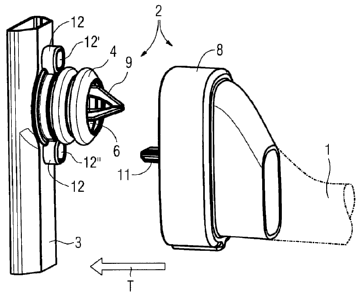
FIG 1 shows a perspective view of coupling means for coupling
of a water transferring pipe with a water supply pipe,
wherein two parts of the coupling means are not yet in
contact,
6
CA 02766321 2011-12-21
WO 2010/149343 PCT/EP2010/003759
FIG 2 shows a sectional view through the coupling means
according to FIG 1,
FIG 3 shows a side view of the coupling means being in contact,
wherein a crockery basket (not shown) is in a lower
position,
FIG 4 shows a sectional view through the coupling means
according to FIG 3,
FIG 5 shows a side view of the coupling means being in contact,
wherein a crockery basket (not shown) is in an upper
position,
FIG 6 shows a sectional view through the coupling means
according to FIG 5.
In FIG 1 and FIG 2 coupling means 2 are shown which can
hydraulically couple a water supply pipe 3 with a water
transferring pipe 1 (shown with dotted lines in FIG 1). The
pipes 1, 3 and the coupling means 2 are part of a domestic
dishwasher. The ascending water supply pipe 3 is preferably
firmly connected with a housing (not shown) of the dishwasher.
The water supply tube 3 can be arranged in a back wall of the
washing cavity (not shown) of the dishwasher. The supply tube
can be arranged behind the back wall or can be an integral part
of it. Its opening can be arranged at a fixed, i. e. an
invariable, height position within the back wall of the washing
cavity. The supply tube opens into the washing cavity. The water
transferring pipe 1 is connected to a crockery basket (not
shown) and supplies a rotating washing arm (not shown) with
water which is arranged at the bottom side of the crockery
basket.
The crockery basket can be pulled out of the washing cavity of
the dishwasher and can be pushed into the same, i. e. it is
movable in a translational direction T relative to the housing
of the dishwasher and the washing cavity respectively.
7
CA 02766321 2011-12-21
WO 2010/149343 PCT/EP2010/003759
Preferably, the translational direction T is essentially
horizontal and the washing cavity is closable by a front door
(not shown).
To ensure a cant-free coupling and de-coupling of the pipes 1, 3
and to avoid that water drops fall down from the movable upper
crockery basket on washed dishes in a lower crockery basket and
make them wet during the coupling and de-coupling process of the
pipes 1, 3 the following design is proposed:
The ascending water supply pipe 3 bears a bellow 4 which has an
essentially cylindrical shape. The axis of the bellow 4 is
directed into the translational direction T. At its open axial
end 5 the bellow 4 has a sealing surface 6. For interaction with
the bellow 4 an adapter 8 is mounted at the corresponding axial
end of the water transferring pipe 1. The adapter 8 has a face
side directed to the bellow 4, where two sealing surfaces 7' and
7" (for two different heights of the basket) are arranged. The
sealing surface 6 of the bellow 4 and the sealing surfaces 7' or
respectively 7" of the adapter 8 cooperate to establish a
hydraulic coupling between the pipes 1, 3.
Therefore, the bellow 4 is elastic (stowable) in the
translational direction. It consists of rubber material or the
like.
A mechanical guidance and also some support is established by a
centering device 9 which is preferably firmly connected with the
water supply pipe 3, as can best be seen in FIG 2. The centering
device 9 also bears the bellow 4 in the depicted embodiment of
the invention. The centering device 9 has a conical shape in its
axial end which is directed to the adapter element 8.
Correspondingly, the adapter element 8 is equipped with resting
surfaces 10' and 10" to establish a guiding and resting area
for the centering device 9.
If the water transferring pipe 3 together with the adapter
element 8 is moved in the translational direction T and the
8
CA 02766321 2011-12-21
WO 2010/149343 PCT/EP2010/003759
bellow 4 contacts the adapter element 8 - see FIG 3 till FIG 6 -
the centering device 9 is resting at one of the resting surfaces
10' or respectively 10", depending of the height position at
which the crockery basket is arranged.
Furthermore, force-uptaking means 11, 12 are arranged at the
coupling means 2 to ensure a defined relative position between
the two pipes. The force-uptaking means 11, 12 comprise a pin 11
which is arranged at the adapter element 8. The water supply
pipe 3 is equipped with a holding element 12. The holding
element 12 has two reception bores 12' and 12" for two
different heights of the crockery basket. As can be seen in FIG
4 for a lower position and in FIG 6 for an upper position of the
basket the pin 11 is engaged in a respective reception bore 12'
or 12".
The force-uptaking means ensure that the bellow 4 hits exactly
to the respective sealing surface 7' or 7" of the adapter
element 8 and takes all forces which could be caused by the
loading of the basket and thus in a undefined height position.
The adapter element 8 comprises at least two flow paths 12' and
13' (see FIG 2) in order to allow to couple the adapter element
8 to the water supply pipe 3 in at least two different heights.
To ensure a defined water flow through the adapter element 8 and
through the respective flow path valve elements 14 are arranged
in the adapter element 8. The valve elements 14 are flaps which
are biased by a spring element (not shown). As can be seen in
FIG 4 and in FIG 6 the centering device 9 with its conical-
shaped end opens the flap 14 when the crockery basket is pushed
into its fully inserted position inside the washing cavity of
the dishwasher. So, the flow of the water is clearly defined by
the respective opened flap 14.
By the dishwasher of the invention_it becomes easily possible to
supply water from the base of the dishwasher to the (upper)
crockery basket without neither canting of the basket when
pulling out the basket of the washing cavity nor applying an
9
CA 02766321 2011-12-21
WO 2010/149343 PCT/EP2010/003759
undue pressure to the front door by a large bellow, wherein
different height positions of the basket are possible.
CA 02766321 2011-12-21
WO 2010/149343 PCT/EP2010/003759
Reference Numerals
1 Water transferring pipe
s 2 Coupling means
3 Water supply pipe (ascending pipe)
4 Bellow
Open axial end
6 Sealing surface
7' Sealing surface
7'' Sealing surface
8 Adapter element
9 Centering device
10' Resting surface
10'' Resting surface
11, 12 Force-uptaking means
11 Pin
12 Holding element
12' Reception bore
12'' Reception bore
13' Flow path
13'' Flow path
14 Valve means (flap)
T Translational direction (horizontal)
11