Note: Descriptions are shown in the official language in which they were submitted.
CA 02766395 2011-12-21
WO 2010/002737 PCT/US2009/048882
APPARATUS AND METHOD FOR OPERATING AN
ENGINE WITH NON-FUEL FLUID INJECTION
CLAIM FOR PRIORITY
[0001] This application claims benefit of and priority from US provisional
application 61/133,176, filed on 28 June 2008.
FIELD OF THE INVENTION
[0002] The invention relates to the structure and mode of operation of
internal
combustion engines, and more particularly to the injection of a non-fuel fluid
such
as water into the combustion chamber.
BACKGROUND OF THE INVENTION
[0003] The increased power and gains in fuel economy obtained by the
injection of water or other non-fuel fluid into the cylinders of an internal
combustion
engine have long been known. Water, added during the compression cycle has
been shown to reduce the engine NOx.
[0004] "ISO conditions" are used when specifying power to account for
changes in ambient temperature, pressure and humidity, and are 59 F (15 C),
atmospheric pressure at sea level (14.54378 psi or 1.01325 bar) and 60%
relative
humidity, respectively. The predominant mass operating within the cylinder to
provide motive power with either the Diesel or Otto cycle is provided by
atmospheric air, heated by the fuel added to the engine. Since the density of
air is
a function of its temperature, pressure, and humidity, the mass within the
cylinders
and hence the resulting power of the engine can be reduced under certain
atmospheric conditions that deviate from the standardized ISO conditions.
Page 1 of 24
CA 02766395 2011-12-21
WO 2010/002737 PCT/US2009/048882
Docket No. 7801-101
[0005] Van Dal U.S. Patent No. 4,589,377 describes the injection of water or
other non-fuel material into an Otto cycle internal combustion engine, the
amount
of non-fuel material being injected and the time of injection being governed
by
such factors as mass of fuel induced, compression ratio of the engine, quality
of
the fuel and pre-selected peak temperature of combustion.
[0006] Nakayama U.S. Patent No. 6,112,705 describes the injection of water
into a compression ignited (i.e., Diesel cycle) internal combustion engine to
lower
NOx emission. Zur Loye et al. U.S. Patent Publication No. 2002/0026926 also
describe the injection of water into a compression ignited internal combustion
engine.
[0007] Singh U.S. Patent Nos. 6,311,651, 6,571,749 and 7,021,272 describe
computer controlled internal combustion engines employing the injection of
water
into each cylinder of the engine, particularly during or after combustion has
been
initiated in the cylinder. Each cylinder of the internal combustion engine is
provided with a pressure sensor and a temperature sensor for measuring the
pressure and temperature in the cylinder. These sensors are connected to a
computer for controlling the rate and duration of water injected into the
cylinder
based on the "energy content" of the cylinder determined by signals received
from
the sensors.
[0008] Hobbs U.S. Patent No. 5,125,366 describes the introduction of water
into an internal combustion engine in which a pressurized source of water is
utilized. A computer and various engine sensors are employed to control the
introduction of water to the cylinders of the engine. Binion U.S. Patent Nos.
5,718,194 and 5,937,799 describe in-cylinder water injection systems for
internal
combustion engines. The water is injected at a high pressure, low temperature.
Miller U.S. Patent No. 4,448,153 describes a water injection system for an
internal
combustion engine that injects water into the cylinders of the engine in
response
to engine temperature. U.S. Patent Publication No. 2006/0037563, Connor U.S.
Patent No. 5,148,776, and Lee U.S. Patent No. 6,892,680 all disclose water
Page 2 of 24
CA 02766395 2011-12-21
WO 2010/002737 PCT/US2009/048882
Docket No. 7801-101
injection for internal combustion engines in which the injection of water is
controlled by a computer in response to one or more sensed engine/cylinder
parameters.
[0009] The disclosures of the foregoing U.S. Patent Nos. 4,448,153, 4,589,377,
5,125,366, 5,148,776, 5,718,194, 5,937,799, 6,311,651, 6,571,749, 6,892,680
and
7,021,272, and U.S. Patent Publication Nos. 2002/0026926 and 2006/0037563
are hereby incorporated by reference herein.
DISCLOSURE OF THE INVENTION
[0010] While the benefits and gains in fuel economy by the injection of water
(or other non-combustible fluid) into the cylinders of an internal combustion
engine
have long been known, some or all of the following features are believed to be
particularly characteristic of various embodiments of the present invention,
both
separately and in combination:
(a) a correction in the injected quantity of water (or other non-combjustible
fluid) injected in response to any change in external air density (pressure
and
temperature) and/or water content (humidity) in the fuel air mixture;
(b) an ability to adjust the amount of water added to the cylinders in the
water
injection control system to enable the engine to produce its rated capacity at
ISO
conditions, independent of current atmospheric conditions;
(c) a high energy ignition system capable of igniting leaner engine mixtures;
(d) an in-cylinder pressure measurement system capable of outputting
absolute (ISO) engine pressures;
(e) a pre-chamber design capable of having its flame pattern modified to be
compatible with different engine geometrics;
(f) a water injector design capable of having its spray pattern modified to be
compatible with different engine geometries and flame patterns of the
pre-chamber igniter for Otto cycle engines, or with the Diesel injector spray
pattern
of a compression ignited engine;
(g) an oil/water separator to remove water from the engine oil;
Page 3 of 24
CA 02766395 2011-12-21
WO 2010/002737 PCT/US2009/048882
Docket No. 7801-101
(h) an exhaust heat exchanger used to preheat the water being injected into
the engine to thereby reduce the viscosity of the water used for in-cylinder
injection and otherwise promote process efficiency;
(i) a secondary condensing heat exchanger to recover water from the exhaust
of the engine;
(j) an organic Rankine variable phase turbine and condenser to extract added
energy from the condensing heat exchanger and exhaust; and
(k) supplementing a first injection of water prior to control combustion
during
the compression stroke with a second injection of water at a higher
temperature
during the expansion stroke.
[0011] Certain embodiments of the present invention provide an internal
combustion operating system that enables the engine to operate at internal
combustion conditions (such as the pressure and temperature inside the
combustion chamber) emulating those occurring at the standard ISO rated
atmospheric conditions and thus able to deliver its ISO rated output
regardless of
atmospheric conditions. A water injector is preferably provided having a plug
end
fitting to a combustion chamber of an internal combustion engine of the spark
ignition or compression ignition type, though which a quantity of water or
other
non-fuel fluid is injected into the combustion chamber; a nozzle is fitted to
the plug
end of the water injector containing a plurality of openings to provide the
water or
other non-fuel fluid to the combustion chamber in a predetermined spatial
spray
pattern. In those embodiments, the temperature and combustion pressure of each
engine chamber as well as the temperature, pressure and humidity of the
atmosphere are preferably monitored and used to control the water injected
into
the combustion chambers. This can not only compensate for lower working fluid
mass within the cylinder due to the air's atmospheric characteristics, by the
addition of mass from the water injected into the cylinder during the
compression
and expansion cycles when operating at full rated power under other than
standard ISO conditions, but can also improve overall engine efficiency when
operating at less than full rated power. In particular, maximum rated power
under
non-ISO conditions may be achieved when the water is pressurized, preheated,
Page 4 of 24
CA 02766395 2011-12-21
WO 2010/002737 PCT/US2009/048882
Docket No. 7801-101
and injected into the cylinder after top dead center whereupon it vaporizes
during
the expansion stroke.
[0012] In accordance with certain characteristic features of other
embodiments,
water injection may be utilized to increase the engine's power to its rated
conditions when atmospheric conditions have reduced the density of air such as
to
reduce available horse power (de-rate the engine). This can compensate for
lower
working fluid mass within the cylinder due to the air's atmospheric
characteristics,
by the addition of mass from the water injected into the cylinder during the
compression and expansion cycles. This is believed to be the result of the
added
mass and therefore the increased pressure inside the combustion chamber. Each
engine cylinder's pressure is preferably monitored during each cycle to obtain
a
gage pressure relative to current actual atmospheric conditions, and the
differences in temperature, pressure and humidity between current atmospheric
conditions and the ISO rating conditions are then used to convert the measured
gage pressure to a corresponding ISO absolute internal pressure at standard
ISO
rating conditions. By comparing this measured ISO absolute internal pressure
with the known absolute internal pressures that are actually produced when
operating at maximum rated output at those same ISO rating conditions, water
injection can be controlled to return the engine to its rated output
regardless of
atmospheric conditions.
[0013] Water injection into the combustion chamber is preferably controlled by
measuring the ambient air's temperature, pressure, and humidity, the water in
the
fuel, and the water injected in the compression cycle, as well as the engine
operational parameters within the combustion chamber such as pressure and
temperature, with the sensor for measuring cylinder pressure preferably being
integrated with the water injector component. This applies to both Otto cycle
(spark-ignited) and Diesel cycle (compression ignited) engines, as well as
modifications of these cycles (such as Miller, Split Chamber, and Compressed
Charge Ignition engines). The resultant new controlled water injection
combustion
cycle not only improves engine efficiency (the degree of improvement being
Page 5 of 24
CA 02766395 2011-12-21
WO 2010/002737 PCT/US2009/048882
Docket No. 7801-101
affected by the temperature, timing and spray pattern of the injected water)
but
also permits the production of the maximum rated power measured at ISO
conditions under all atmospheric conditions by means of the time controlled,
spatially patterned addition of water (or other appropriate non-fuel fluid)
directly
into the combustion chamber.
[0014] Another characteristic feature of certain embodiments of the invention
is
the introduction of a non-fuel fluid such as water into all cylinder chambers
with a
unique spray pattern designed for each engine with its unique cylinder and
piston
geometry, preferably controlling both the spatial pattern of the injected
water into
the cylinder, as well as the spatial pattern of the fuel's ignition source
within the
cylinder.
[0015] The injectors, igniters, and/or pressure sensors are preferably
combined
into a single hydrometer device for each cylinder, having a nozzle arrangement
at
its plug end that intrudes into the combustion chamber and is preferably
designed
to be secured in place using the standard thread specifications for spark
plugs
and/or Diesel injectors, or in an alternative embodiment by means of
conventional
Diesel injector holding clamps. This enables both used and new equipment to be
conveniently upgraded in the field to take advantage of many benefits of the
various water injection technologies herein described. For spark-ignited
engines, a
high energy pre-chamber igniter is preferably integrated with the water
injector to
form a "pyrohydrometer" igniter-injector which independently controls both
ignition
of the compressed fuel air mixture within the combustion chamber and the
injection of water at the appropriate time (or times) during the
compression/expansion cycle. For diesel and other compression ignited engines,
the water and fuel are preferably independently injected into the combustion
chamber by means of a "diesel hydrometer" injector equipped with two sets of
nozzle jets, with the water jets having a spatial spray pattern that
complements
that of the diesel jets.
Page 6 of 24
CA 02766395 2011-12-21
WO 2010/002737 PCT/US2009/048882
Docket No. 7801-101
[0016] In accordance with yet another important characteristic of certain
other
preferred embodiments, a pre-combustion chamber may be incorporated into the
water injector design such that a higher energy ignition source exists
permitting
leaner combustion chamber mixtures (such as would occur with water injection
during compression) to be ignited. The pre-combustion chamber can also be
used for special fuel addition, such as hydrogen gas, for purposes of better
pre-combustion with higher velocity jets going into the combustion chamber, as
well as providing lower overall engine emissions with extremely lean fuel
mixtures
as can occur with large quantities of water injection. The non-fuel fluid can
be
modified by the addition of peroxide, or urea, or other additives or
lubricants to
modify the NOx, CO, characteristics of the engine exhaust or the lubricity of
the
cylinder walls. These additives can also be a function of the measured
atmospheric parameters as well as external exhaust measurements.
[0017] For diesel engines, liquefied natural gas (LNG) or compressed natural
gas (CNG) is preferably substituted for a substantial portion (preferably from
about
60% to 98%) of the normal diesel fuel by means of an added fuel input (either
CNG or LNG) to the diesel hydrometer, preferably including additional injector
outlets in the injector nozzle for the LNG or CNG substitute fuels. Similarly,
by
injecting a low volatility fuel (such as hydrogen or an oxygen hydrogen
mixture
(Rhodes' gas or Brown's gas)) that will be ignited only after it has entered
the
main combustion chamber (preferably by means of additional passageways
through the hydrometer), NOX can be reduced in the engine exhaust. This is
believed to be due to the high velocity flame's ability to ignite extremely
lean fuel
mixtures as can occur with high quantities of water injection. Addition of
these
high velocity flame fuels into the combustion chamber is believed to
concentrate
the ignition closer to top dead center, thus reducing compression pumping
losses
and further improving engine efficiencies.
[0018] An engine controller, with appropriate sensor inputs, is preferably
utilized to monitor all of the engine's internal operating parameters,
external air
temperature, pressure and humidity, water injection temperature, water content
in
Page 7 of 24
CA 02766395 2011-12-21
WO 2010/002737 PCT/US2009/048882
Docket No. 7801-101
fuel and other fuel parameters. These input parameters are then used by the
controller to control the timing of water injection as well as the amount and
temperature of water injected into each cylinder with each engine cycle as
well as
the timing of the ignition system for each cylinder. Especially when combined
with
an optimal water injection spray pattern inside the combustion chamber, this
results in improved engine efficiency when operating at or less than full
rated
power. Since multiple parameters are input into the controller from different
sensor in different cylinders, the water injection/ignition timing controller
preferably
also evaluates whether each individual sensor is operating properly.
[0019] The injection water can have its viscosity modified prior to injection
by
using the exhaust heat to raise its temperature. A heat exchanger by-pass
system
permits a full range of water temperatures. This change in viscosity can
reduce
the water pumping load required for injection, as well as have an effect on
the
spray pattern within the combustion chamber. The cycle efficiency can also be
improved by recovering otherwise wasted heat from the engine exhaust to
preheat
the water before it is injected into the cylinder.
[0020] For turbo-charged Otto cycle engines, water injection can be applied by
either (a) misting after the turbo charger, (b) misting prior to each cylinder
intake,
or (c) direct injection into the combustion chamber during the intake or
compression stroke or any combination of the above. The water injection can be
used to further increase engine efficiency by removing the heat of compression
of
the turbo charger (instead of using an inner cooler) as well as to control
engine
knock (engine pre-ignition or detonation). The efficiency of the Otto cycle
can be
improved by increasing the pressure ratio and avoiding engine knock by cooling
the engine air with water injection to below a temperature inducing engine
knock.
An engine knock sensor is preferably added to ensure that engine knock will
not
occur due to cylinder temperature rise prior to ignition.
[0021] A water/oil separator is preferably included in the water injection
system
to remove the water from the engine oil. During engine operation, the engine's
Page 8 of 24
CA 02766395 2011-12-21
WO 2010/002737 PCT/US2009/048882
Docket No. 7801-101
combusted gasses mix with the engine oil due to gaps in the piston rings and
piston ring clearance, creating the potential for water to be mixed with the
engine
oil.
[0022] In accordance with another important characteristic of certain
preferred
embodiments, the engine exhaust can be further used to produce energy and
recover a major portion of the injected water by installing a condensing heat
exchanger and/or a turbo generator. The heat exchanger can either be made
from acid-resistant metals or Teflon-coated metal to resist attack from the
slightly
acidic exhaust gases. An organic Rankine turbine employing a variable phase
turbine or trilateral cycle with R245fa (1,1,1,3,3-pentafluoropropane) and
condenser can be used to extract energy from the condensing heat exchanger
and condense water for injector reuse. Atmospheric air can be blended into the
engine exhaust gas to provide the proper temperature conditions for the
organic
turbine's working fluid within the heat exchanger.
[0023] This invention finds utility in a wide range of technical applications,
including transportation and power generation, and will typically result in an
increase in power and efficiency over what has heretofore been feasible. For
use
on locomotives and ships, a turbo generator responsive to the exhaust gasses
may provide additional power; the required injection water can be transported
by
the locomotive or can be produced aboard ship by reverse osmosis. For landfill
gas (LFG) and other biofuels having a high water content, the water in the
fuel
performs a similar mass enhancing function as the water being directly
injected
into the combustion chamber, so rather than being a contaminant that should be
filtered out, it is simply measured and provided as an input to the water
injection
controller.
[0024] For a more complete understanding of the present invention, reference
is now made to the following detailed descriptions of a few representative
presently preferred embodiments and to the accompanying drawings.
Page 9 of 24
CA 02766395 2011-12-21
WO 2010/002737 PCT/US2009/048882
Docket No. 7801-101
BRIEF DESCRIPTION OF THE DRAWINGS
[0025] FIG 1 is a schematic depiction of a 16 cylinder engine incorporating
water injection in accordance with this invention;
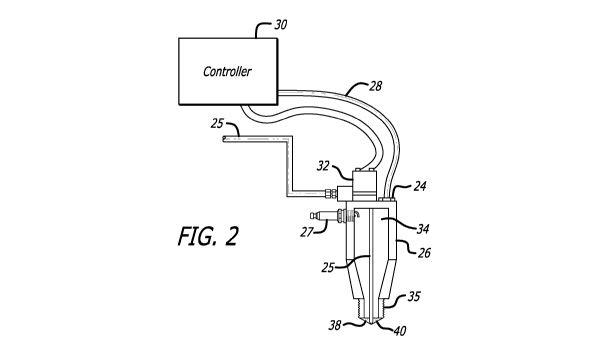
[0026] FIG 2 is a schematic depiction of a spark ignited igniter-injector
("pyrohydrometer") device for use in a spark ignition engine in accordance
with an
embodiment of this invention;
[0027] FIG 3 is a schematic depiction of a Diesel ignited (micro pilot)
pyrohydrometer device for use in a spark ignition engine in accordance with
another embodiment of this invention;
[0028] FIG 4 is a schematic depiction of an pyrohydrometer for use in a spark
ignition engine that also contains an injector for hydrogen or Brown's gas in
accordance with another embodiment of this invention;
[0029] FIG 5 is an enlarged view of the plug end of the pyrohydrometer of FIG
2 including the igniter-injector nozzle;
[0030] FIG 6 depicts a first arrangement of jet holes for the igniter-injector
nozzle of FIG 2;
[0031] FIG 7 depicts an alternative arrangement of jet holes for the
igniter-injector nozzle of FIG 2;
[0032] FIG 8 is a schematic depiction of a 16 cylinder engine as shown in FIG
1, but modified for use with liquefied natural gas (LNG);
[0033] FIG 9 is a schematic depiction of a 16 cylinder engine as shown in FIG
8, but modified for use with compressed natural gas (CNG);
[0034] FIG 10 is a diesel injector with water injection ("diesel hydrometer");
and
[0035] FIG 11 is a diesel hydrometer with CNG or LNG injection; and
Page 10 of 24
CA 02766395 2011-12-21
WO 2010/002737 PCT/US2009/048882
Docket No. 7801-101
[0036] FIG 12 shows a thermodynamic model for evaluating different
embodiments.
DETAILED DESCRIPTION OF PREFERRED
EMBODIMENTS
[0037] For ease of reading, the following description will generally refer to
the
use of water as the non-fuel fluid, but it will be understood that other non-
fuel
fluids can be used. Thus, while water is an obvious choice as the non-fuel
fluid to
be injected into the combustion chamber as the added mass, other suitable
fluids
can be used, including inert gases such as argon, nitrogen, carbon dioxide,
and
ammonia, as well as oxygenated water combinations.
[0038] Referring to FIG 1, a sixteen cylinder engine 10 is provided with the
present improvements. An air sensor 12 provides temperature, pressure, and
relative humidity of the ambient air. From this atmospheric data and from the
current mass flow rate of the incoming engine air, the air density entering
the
engine and the air mass within any given engine design configuration can be
determined.
[0039] Processed water (with or without additives) is supplied to a high
pressure regulated pump 14. The pump provides high pressure water to each
cylinder 16 of the engine 10. The water first passes through an exhaust heat
exchanger 18 which raises the temperature of the water. The water is used in
both the engine's compression cycle to prevent knock, as well as the engine's
expansion cycle to provide added power and improve cycle efficiency. During
the
initial compression cycle, the water can be either (a) directly injected into
the
cylinder, or (b) injected into the compressor exhaust of the turbo charger, or
(c)
injected into the intake valve, or (d) any combination of the above.
[0040] Each cylinder 16 is instrumented with a knock sensor 20, a temperature
sensor 22, and a pressure sensor 24 (shown in FIG 2). The pressure sensors are
calibrated to read pressure based upon ISO conditions rather than gage
pressure.
Page 11 of 24
CA 02766395 2011-12-21
WO 2010/002737 PCT/US2009/048882
Docket No. 7801-101
The corrected ISO data is calculated by using pressure, temperature and
humidity
inputs from the air sensor 12 (and/or equivalent data derived from a mass flow
sensor in incoming air stream) and also takes into account the additional mass
attributable to any water or water additives contained in the fuel.
[0041] Referring additionally to FIG's 2, 3 and 4, for a spark ignition engine
each cylinder 16 is fitted with an igniter-injector control device capable of
fitting
within the engine's conventional spark plug screw pattern The igniter-injector
control device is preferably in the form of a pyrohydrometer 26 that controls
the
ignition pattern and timing within each cylinder 16, the water spray pattern,
and its
timing within each cylinder 16, and by means of the combustion pressure sensor
24 monitors the pressure within each cycle. Water is provided from a high
pressure water supply to a water line 25. Each pyrohydrometer contains a
pressure sensor 24 to make sure that the manufacturer's ISO rating conditions
are
not exceeded. The combustion pressure sensor 24 connects over an electrical
line 28 to a master controller 30. The pressure sensor output is transmitted
as (or
is converted to by controller 30) an absolute ISO pressure rather than a
relative
gage pressure. Water quantity and timing are controlled by the master
controller
30 via a water control solenoid 32 to match the ISO rating of the engine,
regardless of atmospheric air conditions, by relating the measured parameters
to
ISO conditions. .
[0042] Oil-purification system 42 is designed to remove any entrapped water in
the oil system. The oil is then returned to the crankcase for engine
lubrication.
[0043] As shown in FIG 2, for a spark ignited engine, the pyrohydrometer 26
design contains a spark plug 27 inserted into a pre-combustion chamber 34
which
directs high energy flames 36 (see also FIG 5) of combusted gases from the
pre-chamber 34 into the combustion chamber via combustion gas passageways
38. The introduction of high-energy flames 36 t into the combustion chamber
(not
shown) to permit combustion of leaner (and therefore more fuel efficient)
mixtures
than would otherwise be possible. The pre-combustion chamber 34 terminates at
Page 12 of 24
CA 02766395 2011-12-21
WO 2010/002737 PCT/US2009/048882
Docket No. 7801-101
its plug end in a threaded injector nozzle 35 provided with the passageways 38
extending into pre-combustion chamber 34 and with water jets 40 in sealed
fluid
communication with water line 25 to provide a water spray pattern that can be
customized to match each piston and head geometry, as well as be compatible
with the igniter-jet pattern. For example, as best seen in FIG 5, the
individual
holes in the threaded nozzle 35 defining water injection jets 40 can be
circumferentially slant drilled at an oblique angle to give the water a swirl
to
thereby promote better mixing with the incoming combustion gases. The proper
injection angles for a given engine configuration can be readily determined
experimentally by sequentially installing different test nozzles each with a
different
series of angled drill holes, and selecting the nozzle drill holes providing
the best
performance.
[0044] As shown in FIG 3, the pyrohydrometer design 26a for a micro pilot
ignition engine using Diesel fuel is similar to that shown in FIG 2, but in
which a
diesel injector 39 is inserted into the pre-combustion chamber 34. The plug
end
35 of the pyrohydrometer 26a is fitted with the engine's ignition device screw
pattern (or other appropriate connector) .
[0045] Referring to FIG 4 a pyrohydrometer 26 is provided for use in a spark
ignition engine that is similar to that of FIG 2, but which also contains an
injector
41 for hydrogen or Brown's gas (a stable stoichiometric "mixture" of di-atomic
and mon-atomic hydrogen and oxygen). The Browns gas can be in addition to
or a substitute for the gaseous fuel entering the pre-chamber 24 via
passageways
38. When Browns gas is fed into the pyrohydrometer 26b as illustrated, then
the
energy of the flame 36 entering the combustion chamber should have very high
energy, thereby enabling lower calorific mixtures to be combusted.
[0046] Referring to FIG 6 and FIG 7, two different pyrohydrometer nozzle
designs 35a and 35b have respective internal connecting regions 37a, 37b that
can produce two different sets of water spray test patterns. In pattern 35a
shown
in Fig 6, the larger gaseous fuel passageways s 38a can be drilled at various
Page 13 of 24
CA 02766395 2011-12-21
WO 2010/002737 PCT/US2009/048882
Docket No. 7801-101
points and orientations within region 37a, with the smaller water jets 40a
fixed,
while in alternate pattern 35b, fuel passageways 38b are fixed and jets 40b
can
be drilled within region 37b.
[0047] Referring to FIG 8, a 16 cylinder engine 10a similar to that shown in
FIG
1 has been modified for use with liquefied natural gas fed from a supply 42 of
LNG
to an LNG pump 44 and drive 46, through an LNG fuel line 48 to the cylinders
of
the engine.
[0048] Referring to FIG 9, the 16 cylinder engine 10b of FIG 8 has been
further
modified for use with compressed natural gas (CNG) fed from a supply 43 of LNG
to an LNG pump 44 and drive 46, through a vaporizer 47, then through a CNG
fuel line 50 to the cylinders of the engine. In an alternative embodiment (not
shown) the CNG could be generated off site and stored and transported in
pressurized tanks, in which case It could then be fed directly at point 47
from a
control valve.
[0049] FIG 10 illustrates a diesel hydrometer for a diesel engine. Its purpose
is
to take the place of the diesel injector in a diesel engine and contains a
diesel inlet
52 and water inlet 54. The injector in FIG 10 in addition to providing diesel
fuel to
the engine in a conventional diesel spray cone 53 also introduces water in a
concentric spray pattern 56 surrounding Diesel spray cone 53, so that the
injected
water surrounds the injected diesel fuel. The amount of water is controlled by
the
controller to bring the engine performance to ISO conditions as well as to
displace
the amount of diesel fuel used.
[0050] The diesel hydrometer in FIG 11 is similar to that in FIG 10 , but can
additionally utilize either CNG or LNG from third inlet 58 as a substitute
fuel for
some or all of the heavier diesel fuel. In addition to the concentric diesel
and
water spray cones 53 and 56, it also provides an outer concentric spray cone
60
formed by a corresponding ring of CNG or an LNG jets to introduce the
alternative
fuel into the combustion chamber. Thus, FIG 11 has 3 spray patterns whereas
FIG 10 has 2 spray patterns. In both cases, the jets can be relocated to form
an
Page 14 of 24
CA 02766395 2011-12-21
WO 2010/002737 PCT/US2009/048882
Docket No. 7801-101
optimal set of spray patterns for a particular combustion chamber geometry,
similar to the pyrohydrometer nozzle designs shown in Figs 6 and 7.
[0051] Tables 1 through 4 show numerical results obtained from a
computerized thermodynamic model of a typical reciprocating engine (in this
case,
a CAT G3516C) modified and operated in accordance with various embodiments
of the present invention, after calibration with its data sheet efficiency
ratings both
at maximum power at standard ISO 3046/1 conditions and as derated at non-ISO
conditions generator efficiency of 96.7% was assumed and constant turbocharger
compressor and expander efficiencies were assumed. Also, the combustion inlet
air flow rate along with the cylinder geometry and compression ratio was used
to
calculate the required turbocharger pressure ratio at ISO (due to lack of a
compressor map, the turbocharger pressure ratio was kept constant in the
model).
The constructed model was mapped through altitude (0 to 12,000 ft),
temperature
(50 to 130 F), and humidity (0% to 100%). The off-design performance was
determined and tabulated. Using the datasheet, the thermodynamic model was
calibrated (for efficiencies of the turbocharger, compression, and expansion).
[0052] The Table 1 data was then generated by adding water injection to the
model at top-dead center and then matching the resultant calculated flame
temperature to that of the ISO reference model without any water injection
(this
was achieved by varying the fuel flow rate). The amount of water determined
the
power increase that could be achieved and this process was iterated until the
power and flame temperature were brought up to ISO conditions. In particular,
it
will be seen from Table 1 that the amount of injection water required to
maintain
full rated output increases at higher altitudes (lower pressures),
experiencing a
noticeable peak at about 100 F (38 C). Table 1 assumes a 60% relative
humidity, the same procedure can be repeated for other ambient humidities, so
that the required injection water flow rate for a given ambient atmospheric
temperature and pressure can be adjusted to take into account the actual
humidity, and also to take into account any water already present in the fuel.
Page 15 of 24
CA 02766395 2011-12-21
WO 2010/002737 PCT/US2009/048882
Docket No. 7801-101
[0053] A more refined version of that thermodynamic model with more
variables (Table 2) was then enhanced (Table 3) to include the benefits of
other
embodiments of the invention. In particular, varying quantities of water were
injected at two different times at two different temperatures during the
compression/decompression cycle, not only to increase power, but also to
increase efficiency. By injecting a small amount of water at a relatively low
temperature (1000 F) before the fuel ignition it was possible to increase the
compression ratio from 11.3 to 14 without auto-ignition because the
temperature
inside the combustion chamber is thereby reduced. In addition to the increased
power and efficiency resulting from the increased compression ratio, the water
injection is also beneficial in reducing losses two-fold. By reducing the peak
temperature, dissociation is reduced, improving combustion efficiency, and
losses
due to jacket water and heat radiation are also lowered. It was found that the
optimum injection point for such efficiency improvements is before the
compression, with no water injection during the stroke. This can be
accomplished
with standard inlet fogging after the aftercooler.
[0054] Further calculations using other modifications to the model also
suggested that the optimal time for injecting water to enhance power was not
at
top dead center (as was assumed for Table 1), since that apparently resulted
in
the water being vaporized when mixed with the combustion gases, thereby
quenching the expansion that would otherwise have occurred and producing an
immediate drop in the pressure and temperature inside the compression chamber
and a resultant reduction in expansion performance. However, if the power
enhancing water injection occurs later, preferably once the gases have
expanded
by a factor of four, then any quenching effect is outweighed by the
improvements
to both efficiency and power attributable to reduced heat losses in the engine
as
well as the expansion of the water. Additionally, if the pressurized water for
the
later occurring injection during the expansion stage is first preheated to a
substantially higher temperature (preferably to about 650 F) using the engine
exhaust and the high temperature water is then squirted onto the piston head
and
Page 16 of 24
CA 02766395 2011-12-21
WO 2010/002737 PCT/US2009/048882
Docket No. 7801-101
walls to both cool the metal surfaces and vaporize, there is a further
increase in
overall efficiency, as reflected in Table 3 (ISO conditions) and in Table 4
(reduced
atmospheric pressure and elevated temperature).
[0055] Although the present invention has been described in connection with
the preferred embodiments, it is to be understood that modifications and
variations
may be utilized without departing from the principles and scope of the
invention,
as those skilled in the art will readily understand. Accordingly, such
modifications
may be practiced within the scope of the appended claims.
Page 17 of 24
CA 02766395 2011-12-21
WO 2010/002737 PCT/US2009/048882
Docket No. 7801-101
Standard
Temp. Pressure Flow Power
F psia lb/stroke lb/hour kW
Turbocharger Exit 412 36.5 0.026707 23075 -555
Water Injection - - - - -
Piston Inlet 130 36.4 0.026707 23075 -502
Compressed 990 1105 0.029384 25388 -1691
Fuel Injection 60 1200 0.000862 745.1 -
Combusted 2876 2634 0.030246 26133 -
Water Injection - - - - -
Expanded 1350 103.1 0.030246 26133 3932
TurboCharger Exit 931 15.2 0.027570 23820 555
Engine Net Power - - - - 1682
Table 2
Altitude (ft)
0 2000 4000 6000 8000 10000 12000
130 0.00 0.69 1.47 2.20 2.90 3.56 4.17
110 0.00 0.73 1.51 2.25 2.95 3.61 4.22
L o 90 0.00 0.72 1.50 2.24 2.95 3.62 4.23
Q 2 70 0.00 0.67 1.46 2.21 2.92 3.59 4.21
50 0.00 0.60 1.40 2.15 2.87 3.54 4.17
Table 1
Page 18 of 24
CA 02766395 2011-12-21
WO 2010/002737 PCT/US2009/048882
Docket No. 7801-101
Increased Compression with Water Inj.
Temp. Pressure Flow Power
F psia lb/stroke lb/hour kW
Turbocharger Exit 385 34.1 0.026707 23075 -522
Water Injection 100 1000 0.000162 140.0 -
Piston Inlet 104 34.0 0.026869 23215 -514
Compressed 1007 1400 0.029098 25140 -1788
Fuel Injection 60 1200 0.000802 693.2 -
Combusted 2796 3221 0.029900 25834 -
Water Injection 650 2500 0.0013 1123 -
Expanded 1125 103.7 0.031200 26957 4041
TurboCharger Exit 909 15.2 0.028971 25031 522
Engine Net Power - - - - 1682
Table 3
12.7 psia (4000 ft), 90 OF Ambient with Water Inj.
Temp. Pressure Flow Power
F psia Lb/stroke lb/hour kW
Turbocharger Exit 435 32.2 0.025105 21691 -540
Water Injection 100 1000 0.000162 140.0 -
Piston Inlet 103 32.1 0.025267 21830 -514
Compressed 1009 1309 0.027372 23650 -1691
Fuel Injection 60 1200 0.000806 696.8 -
Combusted 2890 3099 0.028179 24347 -
Water Injection 650 2500 0.0013 1123 -
Expanded 1180 101.2 0.029479 25470 3926
TurboCharger Exit 947 13.4 0.028971 23650 540
Engine Net Power - - - - 1682
Table 4
Page 19 of 24