Note: Descriptions are shown in the official language in which they were submitted.
CA 02766428 2016-10-21
TRACKING METHOD AND MEASURING SYSTEM HAVING A LASER TRACKER
FIELD OF THE INVENTION
The invention lies in the field of measurement technology and relates to a
tracking
method and to a measurement system with a laser tracker. The tracking method
serves for the
automatic tracking of a target point, in particular of a moving target point,
with the measurement
beam of a laser tracker. The measurement system with the laser tracker is
equipped for carrying
out the method.
BACKGROUND
=
So-called laser trackers are frequently applied for measurement of the
position of moving
target points. The term laser trackers is to be understood as devices which
comprise at least one
distance meter operating with a focussed laser beam (called measurement beam
in the following
description). For example, the direction of the measurement beam is set to the
target point with
the help of a mirror which is rotatable about two axes, and is detected with
angle sensors
. assigned to the rotation axes. The target point to be measured is provided
with a retro-reflector
(in particular cube-corner prism or arrangement of three mirrors which are
perpendicular to one
another), wherein the retroreflector reflects the measurement beam of the
laser tracker which is =
incident thereon, back to this laser tracker. Thereby, the reflected
measurement beam runs
coaxially to the emitted measurement beam when the measurement beam hits the
reflector in an
exactly central manner, and runs offset parallel thereto, when the measurement
beam does not hit
the reflector in a centric manner. An absolute distance between the laser
tracker and the target
point and/or a change of this distance is deduced from a comparison of the
emitted and reflected
= laser light, depending on the embodiment of the tracker. The position of
the reflector or of the
target point relative to the tracker is computed from the angles detected by
the angle sensors and
the distance detected by the distance meter.
A part of the reflected measurement beam is usually led onto a PSD (position
sensitive
device). One can infer the parallel shift of the reflected relative to the
emitted measurement
beam, from the position, in which the reflected measurement beam is incident
on the light-
sensitive surface of the PSD. The measurement data which is determined by way
of this defines
= the parallel offset of the reflected measurement beam and is used for a
control of the
measurement beam direction, in a manner such that the measurement beam follows
the target
point (tracking) when this moves. This means that by way of a suitable change
of the
measurement beam direction or the alignment of the mirror aligning the
measurement beam, one
CA 02766428 2016-10-21
2
ensures that the parallel offset between the emitted and reflected measurement
beam is reduced
or remains as small as possible.
It is evident that the control of the measurement beam direction by way of the
parallel
offset between the emitted and the reflected measurement beam, although having
a small delay,
however has a delay which is not negligible and limits the speed at which a
target point may
move and thereby be tracked. If the target point moves more rapidly, the
measurement beam,
before its direction can be suitably corrected, no longer hits the reflector,
and the tracking as well
as positioning, are interrupted by way of this. The same may happen if an
obstacle gets between
the tracker and the target point, so that the measurement beam is interrupted.
If the laser tracker
or the measurement beam of the laser tracker "loses" the reflector, the
operating person is made
aware of this and a search routine can be started given a suitable design of
the tracker.
The measurement of the position of the target point and its tracking by the
measurement
beam can be assumed again as soon as the target point is "found" again, which
is to say that the
measurement beam is again incident on the reflector and is reflected by this,
for which the
distance measurement must be newly initiated as the case may be. The mentioned
tracking =
interruptions become more frequent, the less controlled are movements of the
target point and
the smaller are the applied reflector and the diameter of the measurement
beam. The same
conditions as during the mentioned tracking interruptions usually also prevail
at the beginning of
a measurement process, when the tracker is not at all yet set onto the target
point.
It is also known to provide laser trackers with an overview apparatus. This
camera which
has an as large as possible field of view (for example over 200 in all
directions), is arranged on
the tracker and is aligned in a manner such that the measurement beam can be
directed onto a
target point recognised on the camera picture. The alignment of the
measurement beam onto this
target point is initiated by an operating person observing the camera picture,
by way of this
operating person suitably indicating the picture region in which the target
point is imaged.
A tracking method and a measurement system with a laser tracker which has two
-tracking modes, and the measurement system switches from one of the tracking
modes into the
other when the measurement beam of the laser tracker "loses" the target point
or "finds it again",
is described in WO 2007/079601 Al. The normal or ordinary tracking mode is the
tracking
which is known for laser trackers and which is based on the measurement beam,
in which thus
for example the parallel offset between the emitted and reflected measurement
beam is detected
and one strives for a reduction of this offset by way of changing the
measurement beam
direction. In the normal tracking mode, the tracker detects the measurement
beam which is
reflected by the reflector, and a determining of the target point position is
possible at any time. In
'the extraordinary tracking mode, in which the measurement system operates
when the tracker
CA 02766428 2016-10-21
=
3
cannot detect the reflected measurement beam, the change of the measurement
beam direction is
controlled by way of data which is recorded by an overview apparatus assigned
to the laser
tracker. The overview apparatus for example is a digital overview camera which
provides picture
s data and has a light-sensitive surface (e.g. CCD) and optics which give the
overview camera a
viewing angle for example of 20 in all directions, which is common for an
overview
apparatus. The overview apparatus can however for example also be a PSD
(position sensitive
device) which is equipped with the same or similar optics and which only
provides position data
with respect to the sensor, thus direction data with regard to the apparatus.
A direction to the
reflector is determined from the data registered by the overview apparatus
and, with a suitable
change in the measurement beam direction, one attempts to direct this onto the
reflector. The
extraordinary tracking mode thus operates without a detection of the reflected
measurement
beam, and an exact determining of the position of the target point with the
help of the tracker is
not possible in the extraordinary tracing mode. The extraordinary tracking
mode is switched on
as soon as no reflected measurement beam is detected in the tracker. In the
extraordinary
tracking mode however, one always checks again and again, as to whether a
reflected
measurement beam is detected or not, and as soon as this is the case, the
system switches again
into the ordinary tracking mode and the position measurement is released.
The described device and the corresponding method thus can localise a "lost"
target point
again and thereafter again determine the position of the target point.
However, their capability of
following rapid changes in the angular position of the target point with
regard to the tracker is
however limited. This is of particular relevance, if the target point is
located close to the tracker,
and a given absolute position change - compared to a target point distanced
further away -
corresponds to a greater change of the angle at which the target point is seen
from the tracker.
Furthermore, it is necessary for the target point to be able to be held in a
relatively calm manner
for localising, until the capture is concluded and the position measurement
can be activated
again.
Similar tracking methods using cameras or sensors with a narrow or wide
viewing angle
are also described in the following three publications:
EP 2 071 283 A2 describes the use of two separate cameras with a wide and
narrow
viewing angle, in each case with their own light source coupled into the
camera optics. The
cameras are arranged separately from one another, one of these with the
viewing axis colinear to
=a distance meter, and operate with visible light. A target recognition is
accomplished in each case
by switching on/off the respective light source and a subsequent difference
formation from the
respective pictures. =
CA 02766428 2016-10-21
4
WO 2009/046763 Al shows two stages with the target tracking, wherein one
switches
over between a close range setting of optics, with a wide viewing angle, and a
long range setting
with a narrow viewing angle.
US 7,292,788 B2 describes a laser-based communication with a satellite,
wherein a
received light beam is tracked with wide field sensors and narrow field
sensors. Fig. 4B shows an
apparatus for a two-stage measurement: either an intermediate/acquisition
track sensor (660) or a
- fine track quad cell (650) is applied, in order to lead a laser beam into a
fibre-optic (640). Other
embodiments or experimental arrangements (Fig. 4A) likewise use two-stage
methods.
SUMMARY OF EMBODIMENTS OF THE INVENTION
In accordance with an aspect of at least one embodiment, there is provided a
tracking
method, in which a target provided with a reflector is tracked by a
measurement beam of a laser
-tracker, wherein in a normal tracking mode, in a tracking unit, the
measurement beam reflected
by the reflector is detected, and a variable for the control of the alignment
of the measurement
beam is computed from the detection, wherein additionally in an extraordinary
tracking mode, in
which, in the tracking unit, the measurement beam reflected by the reflector
is not detected,
variables for the control of the alignment of the measurement beam are
computed from data
which is acquired by at least one further apparatus, and wherein the laser
tracker comprises a
capture unit and an overview apparatus, wherein the capture unit as well as
the overview
apparatus have a known position and orientation relative to the measurement
beam, the capture
unit comprises a detection region which lies between the detection region of
the tracking unit and
the detection region of the overview apparatus, and the method in the
extraordinary tracking
mode comprises the following steps: in the case that the target is detectable
by the capture unit,
controlling the alignment of the measurement beam in accordance with an angle
at which the
target is visible to the capture unit, and checking as to whether the target
can be detected by the
tracking unit; in the case that the target can then be detected by the
tracking unit, changing over
to the normal tracking mode; in the case that the target can only be detected
by the overview
apparatus, controlling the alignment of the measurement beam in accordance
with an angle at
which the target is visible to the overview apparatus, and testing as to
whether the target can be
detected by the capture unit.
In accordance with an aspect of at least one embodiment, there is provided a
measurement system with a laser tracker, with which a target provided with a
reflector can be
tracked by a measurement beam of a laser tracker, wherein the laser tracker is
designed, in a
normal tracking mode, with a tracking unit, to detect the measurement beam
reflected by the
reflector and to compute a variable for the control of the alignment of the
measurement beam
=
CA 02766428 2016-10-21
from the detection, wherein additionally, in an extraordinary tracking mode,
in which the
measurement beam reflected by the reflector cannot be detected in the tracking
unit, the laser
tracker is designed to compute variables for the control of the alignment of
the measurement
beam from data which is acquired by at least one further apparatus, and
wherein the laser tracker
comprises a capture unit and an overview apparatus, wherein the capture unit
as well as the
overview apparatus have a known position and orientation relative to the
measurement beam, the
capture unit comprises a detection region which lies between the detection
region of the tracking
unit and the detection region of the overview apparatus, and the laser tracker
is designed, in the
extraordinary tracking mode: in the case that the target can be detected by
the capture unit, to
control the alignment of the measurement beam in accordance with an angle at
which the target
is visible to the capture unit, and to check as to whether the target can be
detected by the tracking
. unit; in the case that the target can be detected by the tracking unit, to
initiate a change-over to
the normal tracking mode; in the case that the target can be detected only by
the overview
apparatus, to control the alignment of the measurement beam in accordance with
an angle at
which the target is visible to the overview apparatus, and to check as to
whether the target can be
detected by the capture unit.
In an embodiment, a target provided with a reflector is tracked by a
measurement beam
of a laser tracker in the tracking method. In a normal tracking mode, the
measurement beam
= reflected by the reflector is detected in a tracking unit, and a variable
for the control of the
alignment of the measurement beam is computed from the detection. In an
extraordinary tracking
mode, in which the measurement beam reflected by the reflector is not detected
in the tracking
unit, variables for the control of the alignment of the measurement beam are
computed from data
which are acquired by at least one further apparatus. Thereby, the laser
tracker comprises a
capture unit and an overview apparatus, wherein the capture unit as well as
the overview
apparatus have a known position and orientation relative to the measurement
beam. The capture
unit comprises a detection region or detection angle which lies between the
detection region of
the tracking unit and the detection region of the overview apparatus.
In an embodiment, the method in the extraordinary tracing mode carries out the
following
steps:
in the case that the target is detectable by the capture unit, controlling the
alignment of the measurement beam in accordance with an angle at which the
target is visible to the capture unit, and checking as to whether the target
can be
detected by the tracking unit;
in the case that the target is then detectable by the tracking unit, changing
over to
the normal tracking mode;
CA 02766428 2016-10-21
6
in the case that the target is only detectable by the overview apparatus,
controlling
the alignment of the measurement beam in accordance with an angle at which the
target is visible to the overview apparatus, and checking as to whether the
target
can be detected by the capture unit.
In other words, thus in the extraordinary tracking mode, the variables for the
control of
the alignment of the measurement beam is computed from data which is acquired
selectively by
the capture unit or by the overview apparatus, and, if necessary, one changes
between the
= localisation of the target with the capture unit and with the overview
apparatus, until the target is
detected with the tracking unit. The described steps are thus carried out
repeatedly until the
transition to the normal tracking mode is effected.
By way of this, the opening angle or the field of view of the overview camera
is no
longer limited by way of the resolution of the overview camera having to be
adequately high, so
that the target can be reliably captured by the tracker. The intermediately
arranged capture unit
captures the target by way of the data of the overview camera, and refines the
alignment of the
tracker such that the target is captured by the tracker.
By way of this, it is possible to increase the viewing angle or detection
range of the
overview apparatus, such that it is also possible to follow the target even
with rapid changes of
the angle at which the measurement apparatus sees the target, thus above all
when the target is
moved close to the measurement apparatus.
Theoretically, in the case that the target can only be detected by the
overview apparatus,
then instead of the alignment of the measurement beam, one can firstly only
carry out an
alignment of the capture unit. Since, as a.rule, the capture unit and the
tracking unit are however
moved with one another, this, as a rule, is also equivalent to the alignment
of the measurement
beam.
In an embodiment, with the transition to the normal tracking mode, one carries
out an
absolute distance initialisation (on the fly), for determining an absolute
distance between the
laser tracker and the target. Such a method is described for example in the
published patent
applications EP 1 647 838 Al and US 2009/0033945. With this, apart from the
azimuth and
elevation of the target (with respect to the. laser tracker), its distance is
also known.
In an embodiment, the overview apparatus comprises a zoom function and with
this an
adjustable detection angle, and, in the case that the target cannot be
detected by the overview
apparatus at a small detection angle, the following steps are carried out:
CA 02766428 2016-10-21
7
increasing the detection angle of the overview apparatus, and checking as to
whether the target can be detected by the overview apparatus;
in the case that the target can be detected by the overview apparatus,
controlling
the alignment of the measurement beam in accordance with the angle at which
the
target is visible to the overview apparatus; and
reducing the detection angle of the overview apparatus; or
optionally, in the case that the target cannot be detected by the overview
apparatus, carrying out a search routine for localising the target by way of
moving
the overview apparatus.
In an embodiment of the invention, by way of a deflection device, selectively
either, in a first operating mode of the deflection device, the tracking unit
and the
capture unit;
or, in a second operating mode of the deflection device, the overview
apparatus
can be aligned or guided with their beam path onto the target. Thereby, the
method comprises the
- following further steps:
operating in the first operating mode, or changing to the first operating
mode,
when the tracking unit or the capture unit detect or search the target,
operating in the second operating mode, or changing to the second operating
mode, when the overview apparatus detects or searches the target.
In these embodiments of the invention therefore, the target is not
simultaneously visible
to the tracking unit and the overview apparatus, for example because the beam
path either of the
- tracking unit or of the overview apparatus can be selectively directed to
the target by way of a
tracking mirror. With this embodiment, although it would be possible - without
the capture unit -
for a moved target to be localised by the overview apparatus and for the
alignment of the
measurement beam to be corrected accordingly, after turning the tracking
mirror however, this
alignment would no longer be correct due to the time delay. Here, the capture
unit permits the
capture of the target even with an imprecise alignment after turning the
mirror.
A target provided with a reflector can be tracked by a measurement beam of a
laser
'tracker, in the measurement system with laser tracker. The laser tracker, in
a normal tracking
mode, is designed to detect the measurement beam reflected by the reflector,
with a tracking unit,
and to compute a variable for the control of the alignment of the measurement
beam from the
detection, wherein additionally the laser tracker is designed, in an
extraordinary tracking mode,
in which the measurement beam reflected by the reflector cannot be detected in
the tracking unit,
to compute variables for the control of the alignment of the measurement beam
from data which
is acquired by at least one further apparatus. Thereby, the laser tracker
comprises a capture unit
and an overview apparatus, wherein the capture unit as well as the overview
apparatus have a
CA 02766428 2016-10-21
8
known position and orientation relative to the measurement beam. The capture
unit comprises a
detection region which lies between the detection region of the tracking unit
and the detection
region of the overview apparatus. The laser tracker is set up, in the
extraordinary tracking mode,
to carry out the above described method steps.
in the case that the target can be detected by the capture unit, controlling
the
alignment of the measurement beam in accordance with an angle at which the
target is visible to the capture unit, and checking as to whether the target
can be
detected by the tracking unit;
in the case that the target can be detected by the tracking unit, initiating a
change-
over to the normal tracking mode;
in the case that the target can only be detected by the overview apparatus,
controlling the alignment of the measurement beam in accordance with an angle
at which the target is visible to the overview apparatus, and checking as to
whether the target can be detected by the capture unit.
In an embodiment, the capture unit uses the same measurement beam as the
tracking unit,
for determining the position of the reflector in its field of view.
Alternatively, the capture unit
itself can emit measurement light which (outside the laser tracker) runs
coaxially to the
measurement beam of the tracking unit and enters with this through common exit
optics.
In an embodiment, the beam path of the measurement beam - and of the
measurement
light of the capture unit, in the case that this is not identical to the
measurement beam - can be
guided by the deflection device onto the target. Then selectively, by way of
the deflection device,
in a first operating mode of the defection device, either the tracking unit
and the
capture unit,
or, in a second operating mode of the deflection device, the overview
apparatus,
with their beam path, can be aligned onto the target.
In some embodiments, the capture unit emits measurement light which is
parallel and not
coaxial to the measurement beam of the tracking unit and enters through
separate exit optics.
Thereby, the capture unit preferably has its own illumination means. Moreover,
the capture unit
and the tracking unit can both operate with infrared light (i.e. be sensitive
to infrared), wherein
preferably spectral sensitivity regions of the capture unit and of the
tracking unit with regard to
incident light are different from one another, and in particular do not
overlap one another. The
two units thus do not react to the light of the respective other unit.
In an embodiment of the invention, the capture unit comprises a picture sensor
for
detecting a picture of the target. Thus not only is a PSD present, which only
provides X and Y
position signals of a light point, but a complete picture, by way of which on
the one hand, as with
CA 02766428 2016-10-21
9
= PSD, readings for tracking the target, but on the other hand also further
functions of the laser
tracker can be realised. Such further functions are for example the
determining of the orientation
of the target, the identification of an object as the target, the tracking of
an object by way of
optical features ("feature detection and object tracking"). With this
therefore, one can also
identify and track objects which are not point-like, or entire light point
arrangements.
BRIEF DESCRIPTION OF THE DRAWINGS
Hereinafter, the subject matter of the invention is explained in more detail
by way of
preferred embodiments which are represented in the accompanying drawings. In
each case there
are shown schematically in:
Figure 1 to 3 different embodiments of the invention; and
Figure 4 and 5 flow diagrams according to exemplary realisations of the
inventive
method.
The reference numerals used in the drawings and their significance are listed
in a
conclusive manner in the list of reference' numerals. Basically, the same
parts have been provided
with the same reference numerals in the figures.
DETAILED DESCRIPTION OF THE DRAWINGS
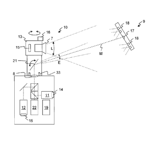
Figure 1 shows a structure of a laser tracker 10 in accordance with an
embodiment. The
laser tracker 10 comprises a tracking unit 1 1 with a measurement beam M, a
capture unit 12 with
a capture region E, and an overview apparatus 13 for localisation, with a
localisation region L.
The laser tracker 10 determines azimuth and elevation as well as the distance
of a target 9,
preferably of a retroreflector 17 on the target 9, with respect to the laser
tracker 10. An absolute
distance meter (ADM) and/or an interferometric distance meter (IFM) are
present in a distance
measurement unit 22, for determining and tracking the target distance. The
overview apparatus
13 can have a zoom function.
The tracking unit 11 and the capture unit 12 use common output optics 8, i.e.
the light is
coupled in from and to the two units onto a common beam path. This contains
the measurement
beam and is aligned by way of a motorically driven tracking mirror 21 onto a
reflector 17, for
example a retro-reflector such as a * prism or a triple mirror.
CA 02766428 2016-10-21
The tracking unit 11 comprises a picture sensor or however a PSD 14 (position
sensitive
device) which produces signals corresponding to the location of a light point
on a surface of the
PSD. The tracking unit 11 operates in the known manner by way of determining
the position of
the reflected measurement beam M on the PSD 14, for the correction of the
alignment of the
measurement beam by way of the computation and control unit 19 and actuators
for moving the
tracking mirror 21. The tracking unit 11 is thus responsible for the highly
precise tracking of the
measurement beam, and for this has a detection region with collimated
(parallel) measurement
light with a width of the measurement light beam of e.g. 1 mm to 2 mm.
The capture unit 12 comprises a camera or a two-dimensional picture sensor 15.
A light
beam produces a light point on the picture sensor 15. This light beam can be
the reflected
measurement beam (i.e. a part of the light coupled out from the measurement
beam), or a second
. beam which preferably runs coaxially to the measurement beam M and is
coupled into its beam
path, but has a different wavelength. The capture unit 12 permits the capture
of a moved target
and the transition for the target tracking by way of the tracking unit 11 also
during the movement
of the target. An opening angle detected by the picture sensor 15 is
preferably about 5 , thus in
total of 10 .
The overview apparatus 13 can be rotatable at least about the vertical axis,
optionally also
about the elevation axis, together with the alignment of the measurement beam.
The overview
apparatus 13 optionally has illumination means 16, by way of which reflecting
elements fastened
on the target (not drawn), can be illuminated and thus can be better visible
to the overview
apparatus 13. It is also possible for the illumination means 16 to be designed
to communicate
with the target. The reflector 17 is preferably provided with illumination
means 18 in order to be
recognised by the overview apparatus 13. The reflector 17 and illumination
means 18 are
arranged on a target 9 which can for example be provided with a scanning tip.
The illumination
means 18 can also be used, in order to determine the orientation of the target
9 by way of the
overview apparatus or a further camera arranged on the laser tracker 10, so
that all six degrees of
' freedom of the target 9 can be determined. The overview apparatus 13 is
preferably a camera
which is sensitive to light in the visible region. An opening angle which is
detected by the picture
sensor 15 is preferably about 5 to 15 . The overview apparatus 13 supplies
picture data to the
computation and control unit 19, for evaluation.
The data of the capture unit 12 and of the tracking unit 11 is likewise
processed by the
computation and control unit 19 and is used with the control of the alignment
of the
measurement beam M for tracking the reflector 17. The computation and control
unit 19 is set
= up, in particular programmed, for carrying out the method according to
the invention.
CA 02766428 2016-10-21
11
The detection region or the field of view or the opening angle of the capture
unit 12 is
thus greater than that of the tracking unit 11, and the detection region of
the overview apparatus
13 is larger than that of the capture unit 12. As a rule, the maximum opening
angle in the
horizontal direction is approximately equal to that in the vertical direction.
The opening angles
.then in both directions are in each case smaller or larger than the opening
angles of the other
units.
=
Figure 2 shows a structure of a tracker 20 with a connectable overview
apparatus 13
according to an embodiment. Thereby, hereinafter, only features which differ
from the first
embodiment are described. The overview apparatus 13 here is not aligned
directly onto the
reflector 17. Instead, exit optics of the overview apparatus 13 are directed
onto the tracking
mirror 21. The tracking mirror 21 is tilted, in order to operate the overview
apparatus 13, so that
.the overview apparatus 13 looks through the tracking mirror 21 to the
reflector 17. No individual
mechanical drive is necessary for aligning the overview apparatus 13 by way of
this. The
overview apparatus 13 cannot be operated simultaneously with the tracking unit
11 or the capture
unit 12 by way of this.
Figure 3 shows a structure of a compact apparatus 39 according to an
embodiment.
Thereby, hereinafter only features which differ from the first embodiment are
described. The
tracking unit 11, the capture unit 12 and the overview apparatus 13 are
arranged on a carrier 31
= in a commonly moved manner. They are thus arranged to one another in a
fixed relation, and
together are aligned onto the reflector 17 by way of a motorically driven
movement of the carrier
31 with respect to a base 32. The capture unit 12 and the tracking unit 11
here in each case have
their own exit optics, but can also have single, common exit optics. Apart
from the illumination
means 16 for the overview apparatus 13, further illumination means 33 for the
capture unit 12
are also present. Preferably, these further illumination means 33 emit light
in the infrared region,
and the capture unit 12 is only sensitive in the infrared region. The tracking
unit 11 preferably
comprises a picture detection sensor, in order to detect the deviation of the
detected measurement
= beam from the desired position.
Figure 4 shows a variant of the course of the method according to an
embodiment. In the
ordinary tracking mode, one checks whether the measurement beam M of the laser
tracker is
reflected by the target 9 or the reflector 17 and is visible to the tracking
unit 11 (first decision 202
"LOCKED?" with respect to the detection of the reflected measurement beam).
If this is the case, then in a first following operation 203 "MEAS/ADJ", the
position of
the reflected measurement beam in the tracking unit 11 (thus for example on a
PSD 14) is
determined, a corrective movement computed therefrom, and the measurement beam
M moved
CA 02766428 2016-10-21
12
(adjusted) accordingly. Subsequently, one continues further with the step of
the first decision
202.
If this is not the case, then one checks as to whether the target 9 is visible
to the capture
- unit 12. Preferably, this is likewise effected by way of the measurement
beam M, but by way of
its projection onto the picture sensor 15 (second decision 204 "CATCH?" with
respect to the
detection of the target).
If this is the case, then in a second following operation 205 "MEAS/ADJ", the
position of
the reflected measurement beam is determined in the capture unit 12, a
corrective movement
computed therefrom, and the measurement beam M is moved (adjusted)
accordingly.
Subsequently, in a third decision 206 "LOCKING?", with respect to the
detection of the reflected
' measurement beam, one checks whether the measurement beam M is visible to
the tracking unit
11.
If this is the case, then preferably an absolute distance measurement is
updated or
is carried out afresh (absolute distance initialisation 207 "ADMinit").
Subsequently, one continues further with the step of the first decision 202.
If this is not the case, then one continues further with the second decision
204.
If the target 9 is not visible to the capture unit 12, then one checks as to
whether the target
.9 is visible to the overview apparatus 13 (fourth decision "OVC?" with
respect to the visibility of
the target). This is preferably effected by way of the reflection of light of
the illumination means
16 at the target, and/or by way of the illumination means 18 at the target 9.
Preferably, these
illumination means and the overview apparatus 13 function with light in the
visible region.
If the target 9 is visible to the overview apparatus 13, then in a third
following
operation 209 "MEAS/ADJ", the position of the reflected measurement beam is
determined in the overview apparatus 13, a corrective movement computed
therefrom and the measurement beam M moved accordingly. Subsequently, one
continues further with the step of the second decision 204.
If the target 9 is not visible to the overview apparatus 13, then for example
a
search routine 210 "SRCH" is carried out. Such search routines are known per
se.
For example, the alignment of the tracker or at least of the optical viewing
axis of
the overview apparatus 13 is changed according to a predefined pattern and
thereby one constantly checks as to whether the target 9 can be found on the
picture of the overview apparatus 13 which corresponds to the respective
alignment, or cannot be found (fourth decision 208). If for example the search
remains without success during a given time or after the completion of a
complete
routine, the system, as the case can be, can stop with a corresponding
communication to the operating person.
CA 02766428 2016-10-21
13
With a start 201 of the measurement system, one preferably begins with the
target search
with the largest viewing angle, thus witlythe fourth decision 208 with respect
to the visibility of
the target. In another preferred embodiment of the invention (not shown in the
figure), the
method begins by way of the target being manually moved with the reflector 17
into the
detection region of the tracking unit 11 and being automatically detected by
the tracking unit 11
and then tracked. Thereupon, the absolute distance measurement is carried out
for the first time
(analogously to "ADMinit").
Optionally, if according to the first decision 202, the reflected measurement
beam is not
detected in the tracking unit 11, the method is not continued with the second
decision 204, but
with the fourth decision 208 with respect to the visibility of the target
(dashed arrow in Figure
4).
Figure 5 shows a further variant of the course of the method according to an
embodiment
for the case that the overview apparatus 13 has a zoom function. The dashed
edged part of Figure
.4 can then be replaced by elements of figure 5. The method then runs as
follows:
If in the fourth decision 208 "OVC?" the target 9 is not visible to the
overview apparatus
13, then firstly in a step of the viewing angle opening 311 "ZOOMOUT", the
zoom objective 7 is
set to a larger viewing angle or detection angle, and in a fifth decision 312
"VIS?", one checks
with regard to the visibility of the target as to whether the target 9 is
visible to the overview
apparatus 13.
If the target 9 is not visible to the overview apparatus 13, then for example
a
search routine 210 "SRCH" is carried out as described above.
If the target 9 is visible to the overview apparatus 13, then in a fourth
following
operation 313 "MES/ADJ", the position of the reflected measurement beam in the
overview apparatus 13 is determined, a corrective movement computed therefrom
and the measurement beam is moved accordingly. In a step of viewing angle
reduction 314 "ZOOMIN", the zoom objective 7 is set again to a smaller viewing
angle and one continues further with the step of the fourth decision 208.
Basically of course, also further variants are possible in the sequence of the
mentioned
steps, which lead to the same result.
In an embodiment, the position of the illumination means 18 at the target 9 is
known and
the overview apparatus 13 already during the capture, thus still during the
extraordinary tracking
mode, determines at least an estimation of the orientation of the target 9, by
way of the imaging
of the illumination means in the overview apparatus 13. Such methods for
determining the
CA 02766428 2016-10-21
14
orientation of a target 9 are known, but only in the context of a normal
tracking mode, in which
the distance between the tracker and the target is precisely known.
CA 02766428 2016-10-21
LIST OF REFERENCE NUMERALS
7 zoom optics
8 common exit optics
9 target
10 laser tracker
11 tracking unit
12 capture unit
13 overview apparatus for localisation
14 PSD
15 picture sensor
=
16 illumination means
17 reflector
18 illumination means on the target
19 computation and control unit
trackers with connectable overview apparatus
21 tracking mirror
.22 absolute distance meter ADM and interferometer 1FM
compact apparatus
31 carrier
32 base
33 illumination means for capture unit
measurement beam
capture region
localisation region