Note: Descriptions are shown in the official language in which they were submitted.
CA 02766455 2011-12-22
WO 2010/148485
PCT/CA2010/000929
SPRINGS FOR SHOES
BACKGROUND
[0001] Field: springs, in particular springs used in shoes. It is common in
human
footwear to have a sole material which compresses to absorb impact energy when
the
mass of the user is transferred to the shoe during each foot strike. Energy is
stored in the
compression of the sole and then released back as a vertical force on the
bottom of the
user's foot. The force required to compress the sole must be high enough to
decelerate the
mass of the user while walking and/or running. Due to the low travel of this
"suspension
system", the bounce frequency of a conventional spring will be higher than the
natural
frequency of the user's walking or running gait. This causes the energy to be
returned at a
higher frequency than is desirable. The inventor has proposed a solution to
this problem
in published United States application no. 2009-0064536 published March 12,
2009.
This patent document proposes further improvements to spring shoes.
SUMMARY
[0002] A sole of a shoe is provided comprising an outsole, an insole and a
pocket in
the outsole, a conical disk within the pocket, and a flange around the
perimeter of the
conical disk extending from the conical disk to a boundary of the fixed pocket
to center
the disk within the fixed pocket while the disk expands or contracts. In an
embodiment,
the flexible flange may act as a seal to prevent the flow of air into and out
of the interior
of the conical disk. In another embodiment, the flexible flange may be
detented to
rotationally position the conical disk within the fixed pocket.
[0003] A spring is also provided comprising a conical disk having a base
and an apex
and a ring spring around the perimeter of the conical disk, in which the ring
spring is
movable in a direction generally perpendicular to the base to adjust the
spring force of the
conical disk. In an embodiment, the ring spring may engage with the conical
disk in a
threaded manner so that the ring spring is movable in the direction generally
perpendicular to the base by rotating the conical disk relative to the ring
spring or the ring
spring relative to the conical disk. In an embodiment, the ring spring may
engage with an
1
CA 02766455 2011-12-22
WO 2010/148485
PCT/CA2010/000929
element radially outward from the ring spring in a manner which allows
vertical
movement and radial expansion of the ring spring but prevents rotational
movement of
the ring spring relative to the element. In a further embodiment where the
ring spring
engages with an element radially outward from the ring spring, the ring spring
may
engage with the element radially outward from the ring spring with tongue and
groove
slots. In an embodiment where the ring spring engages with an element radially
outward
from the ring spring, the element radially outward from the ring spring may be
a damper
ring.
[0004] A spring is also provided comprising a conical disk and a damper
ring around
the perimeter of the conical disk, in which when the conical disk is
compressed the
damper ring is caused to expand. In an embodiment, when the conical disk is
compressed
the damper ring may not be caused to expand until part way through the
compression of
the conical disk. In an embodiment, the creep modulus of the damper ring may
be higher
than the spring constant of the conical disk. In an embodiment, where there is
also a ring
spring, the creep modulus of the damper ring may be higher than the spring
constant of
the ring spring.
[0005] A spring is also provided comprising a conical disk having a base
and an apex,
a ring spring around the perimeter of the conical disk, in which the ring
spring is movable
in a direction generally perpendicular to the base to adjust the spring force
of the conical
disk, and a damper ring around the perimeter of the conical disk radially
outward from
the ring spring, the damper ring providing a damping resistance that varies
depending on
the position of the ring spring in the direction generally perpendicular to
the base. In an
embodiment, the damper ring may also have a cross sectional thickness that
varies over
the direction of movability of the ring spring.
[0006] A spring is also provided comprising a conical disk having a base
and an apex,
in which when the apex is pushed towards the base the spring provides an
opposing force
having a center of force, and means for changing the position of the center of
force in a
direction parallel to the base.
[0007] A spring is also provided for placement between the insole and the
outsole of a
shoe, the spring comprising a conical disk having a base and an apex, and an
eccentric
2
CA 02766455 2011-12-22
WO 2010/148485
PCT/CA2010/000929
ring or cam that can be rotated to accomplish a change of position of the apex
relative to
the insole.
[0008] A biased damper and spring in combination is also provided, the
damper
comprising a flexible container and a deformable or fluid substance contained
within the
flexible container. In an embodiment the deformable or fluid substance may be
a liquid, a
slurry, a powder, or a deformable solid, and may in particular comprise
polysiloxane-
boron, silica particles suspended in polyethylene glycol, or a shear-
thickening fluid. In an
embodiment the flexible container may be an extensible container. In an
embodiment
where the container is extensible it may comprises polyurethane. In an
embodiment the
spring may comprise a conical disk and the biased damper may be placed to
resist
compression of the conical disk at or near full compression of the conical
disk.
[0009] In any of the above embodiments where there is a damper ring the
damper ring
may comprise polyurethane. In any of the above embodiments where there is a
damper
ring the damper ring may be made of a combination of materials. In any of the
above
embodiments where there is a damper ring there may be one or more additional
damper
rings in which when the conical disk is compressed the damper rings begin to
expand
progressively during the compression of the conical disk.
[0010] A spring is also provided comprising a conical disk having a base
and an apex,
in which when the apex is pushed towards the base the spring provides an
opposing force
having a center of force, in which the conical disk is asymmetrical so that
the conical disk
that can be rotated to accomplish a change of the center of force position.
100111 A spring array is also provided for a spring shoe having a sole, the
spring array
comprising an array of springs, each spring of the array of springs having a
spring range
of travel under compression of the spring by a foot supported by the spring
array, each
spring having a spring rate that varies with the compression of the respective
spring to
provide a reducing force resisting compression over at least a portion of the
spring range
of travel as the spring compresses, and a biased damper associated with the
array of
springs, the biased damper opposing compression of the array as the springs of
the array
compress towards maximum compression and the biased damper being external to
the
springs in the array. In an embodiment the springs may surround the biased
damper.
3
[0012] A spring array is also provided for a spring shoe having a sole, the
spring array
comprising an array of springs, each spring of the array of springs having a
spring range of
travel under compression of the spring by a foot supported by the spring
array, each spring
having a spring rate that varies with the compression of the respective spring
to provide a
reducing force resisting compression over at least a portion of the spring
range of travel as
the spring compresses, and a biased damper associated with the array of
springs, the biased
damper opposing compression of the array as the springs of the array compress
towards
maximum compression and the springs of the array having spring rates that vary
and
depend on the location of the spring in the array. In an embodiment each
spring may
comprise at least a rigid member and an extensible member. In an embodiment
the
thickness of at least some of either or both of the extensible members and the
rigid
members may vary across the array. In an embodiment the rigid members and the
extensible members may be made of the same material but the extensible members
being
thinner than the rigid members.
[0013] Logical combinations of any of the above embodiments may also be
used. Any
of the springs, dampers and spring and damper combinations may be used in a
shoe
comprising an outsole and an insole, and the spring, damper or spring and
damper may be
situated within either the outsole or insole or within both, as for example
when situated
between the outsole and insole.
[0014] These and other aspects of the device and method are set out in the
claims.
BRIEF DESCRIPTION OF THE FIGURES
[0015] Embodiments will now be described with reference to the figures, in
which like
reference characters denote like elements, by way of example, and in which:
[0016] Fig. 1 is a side section view of a conical disk between an insole
and an outsole,
having a flexible flange, threaded ring spring, damper ring, and eccentric
pronation/suponation adjustment;
[0017] Fig. 2 is a detail section view of the adjustable ring spring and
damper of Fig. I
in an at-rest position;
4
CA 2766455 2018-06-19
CA 02766455 2011-12-22
WO 2010/148485
PCT/CA2010/000929
[0018] Fig. 3 is an isometric view of the disk of Fig. 1 between an insole
and an
outsole;
[0019] Fig. 4 is a top view of the disk of Fig. 1 in a shoe showing an
inner rotation
drive to adjust the spring and damping rate and an outer rotation drive to
adjust for
pronation and suponation;
[0020] Fig. 5 is a top view of a disk in an outsole showing detentes;
[0021] Fig. 6 is a top view of a portion of an adjustable ring spring with
a damper ring
[0022] Fig. 7 is a top view of an asymmetric conical disk;
[0023] Fig. 8 is a slightly elevated back view of a conical disk;
[0024] Fig. 9 is a section side view of a conical disk between an insole
and an outsole,
having a damper comprising a flexible container containing a viscous fluid
within the
conical disk and another such damper between the insole and the outsole
outside the
conical disk; and
[0025] Figs. 10-13 show several possible arrays of springs.
DETAILED DESCRIPTION
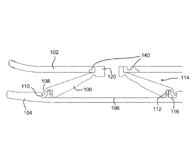
[0026] Referring to Fig. 1, a side section view of an exemplary conical
disk 100 is
shown. The conical disk is shown here extending between an insole 102 and an
outsole
104 of a shoe. In the embodiment shown the outsole defines a pocket 106. A
flexible
flange 108 around the perimeter of the disk allows the disk to compress while
staying
centered in a fixed pocket. This flange can be used to air seal the inside of
the disk. It
can also be used as a flexible detent member for rotational adjustment of the
disk as
described below. The flexible flange 108 extends between conical disk 100 and
edge 110
of pocket 106 to keep the conical disk centered within the pocket.
[0027] Around the circumference of the conical disk 100 lies ring spring
112. The ring
spring and the conical disk cooperate to act as a spring 114 with a spring
rate that reduces
when the spring is compressed. Compression of the sole of the shoe by moving
the insole
and outsole towards each other causes compression of the conical disk and
expansion of
the outer circumference of the conical disk. The expansion of the outer
circumference of
the conical disk is resisted by the material comprising the outer
circumference of the
conical disk and by the ring spring 112 to provide a spring force of the
conical disk
CA 02766455 2011-12-22
WO 2010/148485
PCT/CA2010/000929
opposing the force compressing the conical disk.
[0028] Adjustment of the spring force may accomplished by moving the ring
spring
112 (preferably made of Delrin or Pebax or some other highly elastic material)
up or
down relative to the conical disk 100. This gives the conical disk more
mechanical
advantage on the spring when the ring spring is in the uppermost position, or
less
mechanical advantage on the ring spring is in the downward most position. Any
number
of positions is possible in-between these extremes. In this way the vertical
spring force
of the assembly can be decreased by moving the spring ring up or increased by
moving
the ring spring down.
[0029] Vertical adjustment of the ring spring 112 can be accomplished by
various
means. A threaded engagement 118 is disclosed here as the preferred
embodiment, most
readily seen in Fig. 2. The preferred method of vertically moving the spring
ring using a
threaded engagement is to prevent the ring spring from rotating, and by
rotating the
conical disk. In this case, the flexible outer flange may be detented to
provide positive
engagement in predetermined positions. When the conical disk is in an
uncompressed
position as shown, the ring spring has the same diameter in an upper or lower
position.
When the conical disk is compressed, the ring spring is expanded to a greater
diameter if
it is in a lower position than if it is in an upper position, and thus the
ring spring provides
a greater force resisting the compression of the conical disk when it is a
lower position
than when it is an upper position.
[0030] Due to the reduction of spring force as the conical disk 100
compresses, in
order to prevent the compression from becoming excessively abrupt towards
maximum
compression, it is desirable to provide a damper to resist compression towards
maximum
compression without providing such a force at maximum compression as would
cause the
spring to prematurely uncompress The damper is designed to provide resistance
to
compression of the shoe sole for the portion of the user's mass and inertia
which is not
effectively opposed by the energy storage and return spring. The damper is
biased so that
it acts only or primarily during the compression phase of the shoe sole
compression and
rebound. During the rebound phase, the combination of the spring and damper
allows the
damper to return to its original shape more slowly, quickly enough so it is
available to
dissipate energy during the next foot strike, but not as quickly as the spring
expands when
6
CA 02766455 2011-12-22
WO 2010/148485
PCT/CA2010/000929
the user heel begins to lift. The damper does not detract from the energy
which is being
returned to the user by the spring.
[0031] A new method is shown of achieving a compression biased damper
which, in
the preferred embodiment, is also adjustable. The basic concept of this new
damper uses
one or more additional rings 116 (only one shown) located around the outside
of the ring
spring (the ring spring may be a separate, and possibly adjustable ring, or it
may be
integrated into the perimeter of the conical disk (not shown here) or the
conical disk may
have enough spring force on its own provided by the flexible flange or some
other feature
or combination of features that the damper ring can be located around the
perimeter of an
interrupted section of the conical disk which has no or very little spring
force
characteristic. The damper ring 116 is preferably constructed of a material or
combination of materials such as but not limited to polyurethane which has a
high creep
modulus or high hysteresis, or which is highly visco elastic (i.e. high
viscosity) such that
it provides significantly more resistance to expansion during compression when
the disk
is compressed in less than half a second than it provides energy return during
contraction
when the disk is allowed to expand in less than half a second. Polyurethane
with a shore-
A durometer of 70 or greater is believed to be adequate for the damper ring in
many
applications but other durometers and/or materials and/or combinations of
materials may
also be used. In this way the damper ring provides compression biased damping
resistance to the conical disk when it is compressed.
[0032] The damper ring 116 may contact the conical disk 100 and/or ring
spring 112
starting immediately during the compression phase, but it preferably fits
loosely around
the perimeter of the conical disk and/or ring spring so it does not begin to
expand until
the disk is partly compressed. Ideally, the damper ring is only forced to
expand as the
spring rate of the other components begins to drop off. In this way, a
constant or
increasing spring rate can be achieved during compression, but due to the
hysteresis of
the damper ring, the total vertical force of the disk and damper will fall off
when the disk
is at full compression so the disk can stay compressed during the mid stride.
The
compression resistance rate of the damper ring can be further refined by using
one or
more additional damper rings which begin to expand progressively through the
compression of the conical disk.
7
CA 02766455 2011-12-22
WO 2010/148485
PCT/CA2010/000929
100331 The force of the damper ring/s 116 may also be adjustable when used
in
combination with the threaded ring spring 112. In the preferred embodiment,
the
threaded ring spring is prevented from spinning via some means such as, but
not limited
to, the tongue and groove interface with the damper ring shown in Fig. 6 This
interface
allows the ring spring to move vertically but not to rotate. One or more tabs
130 of ring
spring 112 fit into corresponding slots 132 in damper ring 116. If a damper
ring is not
used, or is not located immediately adjacent to the ring spring, then these
tabs would be
larger to allow radial expansion of the ring spring and may be positioned in
slots in edge
110 of outsole pocket 106. The damper ring 116 (more than one can be used in
series or
parallel) is allowed to expand radially but is prevented from rotating by some
means such
as but not limited to a tongue and groove arrangement as also shown in Fig. 6.
One or
more tabs 134 of damper ring 116 extend into corresponding slots 136 in edge
110 of the
outsole pocket 106. There may also be one or more detents 138 in the edge 110,
and/or
on the flexible flange 108, to provide positive rotational positioning of the
conical disk.
These features are also shown in Fig. 5 in the context of the whole conical
disk 100
positioned within outsole 104. The damper ring can be in initial contact with
the ring
spring before compression of the conical disk, but it is preferably large
enough in
diameter to allow the conical disk to compress partially before the damper
ring must
begin expanding. When the ring spring is at the top (in the lightest user
weight position)
the ring spring only expands against the top part of the damper ring. The
combination of
increased mechanical advantage of the conical disk on the ring spring, and the
fact that
the ring spring must only flare the top of the damper ring, allows the damping
in this
position to be minimized. When the ring spring is at the bottom position (at
the heaviest
user weight position) the ring spring must expand the bottom section of the
damper ring.
The combination of decreased mechanical advantage of the conical disk on the
ring
spring, and the fact that the ring spring must stretch the thicker bottom part
of the damper
ring, allows the damping in this position to be maximized. The damper ring can
be of a
consistent cross sectional profile from top to bottom (or with a narrower
cross section at
the bottom than the top) but preferably has a larger cross section at the
bottom than the
top, as shown in Figs. 1 and 2. This allows the damping to increase at a
greater rate than
the spring rate as the spring ring is threaded downward. It is believed by the
inventors
8
CA 02766455 2011-12-22
WO 2010/148485
PCT/CA2010/000929
that higher damping rates will allow for a wider range of users than will
higher spring
rates. The advantage of increasing the damping at a greater rate than the
spring rate is to
allow greater variations in the spring/damping characteristics of the
assembly. It is
further believed that a damper ring that increases in cross sectional
thickness exponential
at the bottom will enable the best shoe performance over the widest range of
user weights
and uses.
[0034] Also disclosed are two methods of adjusting the PowerDisk for
different users
with regard to the tendency to pronate or suponate. The preferred embodiment
uses an
eccentric ring 140 at the apex 120 of the disk to move the position the disk
apex laterally
at various positions under the user's heal. The second method uses an
asymmetric
conical disk 150 design which can be positioned rotationally by the user to
achieve
different effects. Both of these methods can be combined with the adjustable
ring spring
and damper ring. A cross section of an eccentric ring 140 is visible in Fig.
1. Fig. 3 shows
the eccentric ring in more detail in the context of a perspective view of a
conical disk 100
between an insole 102 and an outsole 104. The position of the apex 120 of the
disk 100
may be adjusted by rotating the eccentric disk 140 relative to the insole 102.
Fig. 4 shows
the embodiment of Fig. 3 from a top view. Also visible on the insole in this
embodiment
are a first set of markings 142 to aid the user in determining the rotation of
the eccentric
disk 140 and a second set of markings 144 to aid the user in determining the
rotation of
the conical disk 100 including its apex 120. Arrows 146 on the eccentric disk
and 148 on
the apex of the conical disk enable the user to determine the rotation of the
disks by
comparing the direction of the arrows with the markings. The arrows may also
be
functional elements for example for engaging with a tool in order to rotate
the respective
disks.
[0035] An alternative embodiment of an asymmetric conical disk 150 is shown
in
Figs. 7 and 8. Fig. 7 shows a top view of the asymmetric conical disk. The
apex 120 is
not at the centre of the disk. As a result when the disk is rotated the
position of the apex
relative to the sole will move. The disk may be rotated by means of an
engagement
element 152 preferably located at or near the centre of the disk.
9
CA 02766455 2011-12-22
WO 2010/148485
PCT/CA2010/000929
[0036] Positive or negative Poisson's ratio materials may be used as live
hinges in
high strain areas of the conical disk as long as these materials have the
ability to form live
hinges without failing over repeated cycles (preferably at least 300,000
cycles).
[0037] Fig. 9 is similar to Fig. 1 but showing additional dampers, one
within the
conical disk 100 and another outside the disk but between insole 102 and
outsole 104. A
viscous liquid, fluid, slurry, powder or other material or combination of
materials 160
with little or no ability to return to its/their original shape such as, but
not limited to,
polysiloxane-boron, silica particles suspended in polyethylene glycol and/or
other types
of shear-thickening fluids with non-Newtonian behavior, (also referred to as
dilatant
fluids) are contained within a flexible and preferably extensible material 162
such as but
not limited to a polyurethane container which acts to return the container and
contents to
its original shape after compression deformation. The viscous material must be
stiff
enough to provide adequate damping through all or the final part of the shoe
sole and
PowerDisk compression. The flexible/extensible container must be stiff enough
to return
the container to near it's original shape before the next compression. A time
of 0.4
seconds should be adequate for most walking and jogging applications. Longer
or shorter
return times may also be used for various applications. The ideal combination
of viscous
material characteristics and container material characteristics is best
determined by
testing in actual running or walking conditions.
[0038] The original shape of the damping material is defined primarily or
completely
by the flexible container. Compression stretches the container and dissipates
energy
primarily via deformation of the viscous fluid. The flexible/elastic container
returns the
viscous material to (or nearly to) its original shape before the next
compression. In Fig. 9,
a first damper 164 of this design is shown within the conical disk 100 to
resist
compression of the conical disk as it nears maximal compression The damper is
shown
in an uncompressed position 168 (darker) and a compressed position 170
(lighter). A
similar damper 166 may be used with the same or a different shape or
configuration on
the outside of the PowerDisk such as behind the PowerDisk to provide initial
impact
energy dissipation. This damper concept can be used with many conceivable
configurations of the PowerDisk invention. Illustrations shown here are
intended as
examples of how it can be used. The damping element is preferably constructed
so
CA 02766455 2011-12-22
WO 2010/148485
PCT/CA2010/000929
compression by a light person will allow the PowerDisk to reach adequate
compression
to store footstrike energy through the mid stride. The disk will also
preferably be
designed to allow compression below this position so additional damping can be
provided
by the further and more complete compression of the damping element/s shown in
this
figure. The same principle also holds true for other damping elements.
[0039] Preferably additional foam and/or deformable material or combination
of
materials is used to act as a full bump stop by increasing the spring force
required to
compress the conical disk at or near full compression. This bump stop may be
of many
different materials or configurations and preferably has a damping quality to
it as well as
an increasing spring force quality at full compression.
[0040] Multiple springs may be included in a shoe, for example in arrays
200, 220,
240 and 260 of Figs. 10-13. Each array 200, 220, 240 and 260 comprises
multiple springs
that have a spring rate that varies with the compression of the sole of a shoe
to provide a
reducing force resisting compression over at least a portion of the spring
range of travel
as the sole compresses. It will be appreciated that the reference to a spring
rate means the
coefficient that relates the force applied by the spring to displacement of
the spring. Thus,
the exemplary arrays are able to return a portion of the compression energy to
the user
after the user's center of gravity is forward of the user's heel (when the
user is walking
forward). Each spring in the arrays may be formed of rigid members 202, 222,
242 and
262 respectively and respective extensible members 204, 224, 244 and 264 that
are
stretched when the rigid member moves under compression from a foot. In the
arrays
200, 220, 240 and 260 the springs are arched non-conical hinged springs. The
rigid
members 202, 222, 242 and 262 are hinged to allow the rigid members to flatten
on
pressure applied to the apex members formed between the rigid members.
[0041] In Fig. 11, the arrays 220 are linear arrays separated by linear
dampers 226 that
are exterior to the individual springs of the arrays. In Fig. 12, the array
240 forms an
annulus around a central damper 246. The dampers 226 and 246 are biased
dampers that
compress with compression of the arrays 220 and 240 but, during foot lift-off
of a wearer,
subsequent expansion of the dampers 226 and 246 lags the expansion of the
respective
springs 220 and 240. The dampers 226 and 246 are oriented to oppose
compression of
the array as the springs compress towards maximum compression. The springs of
the
11
CA 02766455 2011-12-22
WO 2010/148485
PCT/CA2010/000929
arrays 200, 220, 240 and 260 provide a more even distribution of forces across
the length
and/or width of the shoe sole, and also to provide a graduated and progressive
compression force as compared with a single spring. Lateral or vertical
variation of
spring material or spring member thickness or hinge member angles may vary to
cause
certain areas or levels to compress first. When different levels compress
first, a more
smooth and progressive compression may be provided which stores energy during
mid
stride even if the sole is not completely compressed. Thus, the springs of the
arrays may
have spring rates that vary and depend on the location of the spring in the
array.
100421 The array 200 of Fig. 10 may use a rigid material (preferably
polypropylene
but many other materials may be used) as a single hinged member or as a series
of
connected (shown) or unconnected (not shown) hinged members 202 which are
loaded in
compression which must elastically deform a central member 204 which is loaded
in
tension and may be of the same material but is preferably a material such as
delrin with
more resilient elastic properties. The array 220 of Fig. 11 is preferably used
in
combination with (and staggered with) one or more other assemblies, also
forming an
array, and also in combination with a compression biased damping element as
shown. In
an array, for example the array 240 of Fig. 12 a number of
increasing/decreasing spring
force components may be combined into one piece of material. The rigid hinged
compression members 242 are thicker than the elastic tension members 244 and
in this
way, an increasing/decreasing spring force is achieved within each individual
"cell"
during compression. Furthermore, the lower springs of the array 240 may be
made easier
to compress (either as a result of thinner elastic members, and/or shallower
angles
between hinged members) so the lower cells compress with less force than the
upper
cells. Other distributions of greater or less force from top to bottom or side
to side or
front to back may also be used with different effects. An array made of all
the same
material is well suited to extrusion process manufacturing for low cost. It
also has the
benefit of working over a wide range of user weights and foot strike forces.
The material
is preferably polypropylene but many other materials such as, but not limited
to,
polyurethane may also be used. In the array 260 of Fig. 13, the hinged members
262 of
each spring pivot on the elastic member 264 of an adjacent spring. In this
way, a specific
effect can be achieved where the springs of the array 260 work together with
adjacent
12
CA 02766455 2011-12-22
WO 2010/148485
PCT/CA2010/000929
springs to affect the spring force as various springs are compressed. As shown
in Fig. 13,
the elastic members 264 which are loaded in tension are preferably
progressively thicker
(and/or the angle of the hinged members 262 becomes progressively steeper)
toward the
top. The material is preferably polypropylene but many other materials such
as, but not
limited to, polyurethane may also be used. The arrays 200-260 may also be
constructed
at one or more angles for smoother transitions.
[0043] Many other variations are possible and have been conceived by the
inventor.
Only the preferred embodiments and configurations are described here. Parts
may also
be in other orientations than are shown in the figures. Multiple disks can
also be used
where a single disk is shown in the figures.
[0044] In the claims, the word "comprising" is used in its inclusive sense
and does not
exclude other elements being present. The indefinite article "a" before a
claim feature
does not exclude more than one of the feature being present. Each one of the
individual
features described here may be used in one or more embodiments and is not, by
virtue
only of being described here, to be construed as essential to all embodiments
as defined
by the claims.
[0045] Immaterial modifications may be made to the embodiments described
here
without departing from what is covered by the claims.
13