Note: Descriptions are shown in the official language in which they were submitted.
CA 02766917 2012-09-17
1
Heat Exchanger and Method for Making
Field of the Invention
[0003] The present invention relates to heat exchangers in general, and, more
particularly, to heat exchangers for Ocean Thermal Energy Conversion systems.
Background of the Invention
(0004] Ocean thermal energy conversion ("OTEC") is a method for generating
electricity based on the temperature difference that exists between deep and
shallow
waters of a large body of water, such as an ocean. An OTEC system utilizes a
heat
engine (i.e., a thermodynamic device or system that generates electricity
based on a
temperature differential) that is thermally coupled between relatively warmer
shallow
and relatively colder deep water.
[0oos] One heat engine suitable for OTEC is based on the Rankine cycle, which
uses a low-pressure turbine. A closed-loop conduit containing a "working
fluid"
characterized by a low boiling point (e.g., ammonia) is thermally coupled with
warm
seawater at a first heat exchanger where the working fluid is vaporized. The
expanding
vapor is forced through the turbine, which drives a turbo-generator. After
exiting the
turbine, the vaporized working fluid is condensed back into a liquid state at
a second
heat exchanger where the closed-loop conduit is thermally coupled with cold
seawater.
The condensed working fluid is then recycled through the system.
[0006] OTEC systems have been shown to be technically viable, but the high
capital cost of these systems has thwarted commercialization. The heat
exchangers are
the second largest contributor to OTEC plant capital cost (the largest is the
cost of the
offshore moored vessel or platform). The optimization of the enormous heat
exchangers
that are required for an OTEC plant is therefore of great importance and can
have a
major impact on the economic viability of OTEC technology.
CA 02766917 2011-12-28
WO 2011/009080 PCT/US2010/042333
2
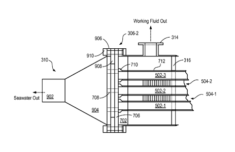
[0007] One of the most efficient and cost-effective types of industrial heat
exchangers is a plate-fin heat exchanger. Plate-fin heat exchangers can have
higher
surface area (due to their potential for high fin packing density) as compared
to other
types of heat exchangers, such as conventional tube and shell, plate-frame,
etc. As a
result, a plate-fin heat exchanger can have higher heat transfer efficiency,
which makes
it an attractive candidate for use in applications that require high fluid
flow rates but are
characterized by low temperature differentials, such as OTEC.
[0oos] One of the highest efficiency plate-fin heat exchangers is the brazed-
aluminum plate-fin heat exchanger, which comprises multiple layers of aluminum
fins
and plates that are made of materials having good thermal conductivity. The
fins and
plates are stacked and joined, using brazing, to form alternating passages for
conveying
fluids. In operation, fluids of different temperatures are passed through the
alternating
passages and heat energy is transferred between the fluids through the fin and
plate
materials.
[0009] Brazing is a well-known, low-cost process for joining mechanical
elements.
It is similar to soldering; however, brazing uses brazing-filler material that
has a higher
melting temperature (typically 450 C) than traditional solder (-250-300 C).
In many
applications, brazing is preferred over soldering because brazing fillers have
higher
structural strength. In fact, brazed connections are often nearly as strong as
the parts
they connect, even at elevated temperatures.
[ocao] In addition, complete assemblies comprising many brazed joints can be
brazed at one time by arranging the assemblies, with brazing-filler material
in place at
each desired brazed joint. The entire arrangement is then heated at the same
time,
which induces the brazing-filler material to melt and fuse to its adjacent
elements. As a
result, the use of brazing offers significant cost advantages over many other
joining
technologies, such as fusion welding, etc.
[0on] Unfortunately, brazed joints are highly susceptible to galvanic-
corrosion
when exposed to a highly electrically conductive medium, such as seawater,
geothermal
fluid, mineral water, polluted water, and salt spray. The typical brazing
process utilizes
a filler aluminum alloy that has a lower melting temperature than the parent
(base)
metal being joined. Thus, the filler metal has different chemical composition
and electric
potential than the parent metal. The dissimilar metals, therefore, create a
galvanic cell
at the joint. Galvanic action at the joint induces metal migration (i.e.,
corrosion). In the
presence of a conductive medium (e.g., seawater), the galvanic action at the
joint is
enhanced, which accelerates degradation of the joint. Furthermore, brazed
joints that
CA 02766917 2014-06-25
3
have failed because of galvanic-corrosion-related degradation usually cannot
be reliably
or cost-effectively refurbished.
Summary of the Invention
[0012] The present invention provides a plate-fin heat exchanger without some
of the costs and disadvantages of the prior art. Embodiments of the present
invention
are particularly well-suited for use in OTEC systems; however, embodiments in
accordance with the present invention are also suited for use in other heat
exchanger
applications, such as nuclear reactors, chemical plants, and the like.
[0012a] Certain exemplary embodiments can provide a heat exchanger
comprising: a first core, wherein the first core comprises; a first layer
comprising a first
channel for conveying a first fluid; and a second layer comprising a plurality
of fins that
define a first plurality of flow channels, wherein the second layer is brazed
to the first
layer to form a brazed joint; a first plate disposed at a first end of the
first core,
wherein the first plate and the first end of the first core are joined via a
first joint that is
galvanic-corrosion-resistant; and a second plate disposed at a second end of
the first
core, wherein the second plate and the second end of the first core are joined
via a
second joint that is galvanic-corrosion-resistant; wherein the first plate and
the first
joint collectively define a first barrier and the second plate and the second
joint
collectively define a second barrier, and further wherein the first barrier
and the second
barrier fluidically isolate the brazed joint from a corrosive medium.
CA 02766917 2014-06-25
3a
[0012b] Certain exemplary embodiments can provide a method for forming a
heat exchanger, the method comprising: forming a first core by joining, to one
another,
a first layer comprising a first channel for conveying a first fluid and a
second layer
comprising a plurality of fins that define a first plurality of flow channels,
wherein the
second layer is brazed to the first layer to form a brazed joint; and joining
a first plate
and the first core at a first end of the first core via a first joint that is
galvanic-
corrosion-resistant; and joining a second plate and the first core at a second
end of the
first core via a second joint that is galvanic-corrosion-resistant; wherein
the first plate
and the first joint collectively define a first barrier and the second plate
and the second
joint collectively define a second barrier; and wherein the first barrier and
the second
barrier fluidically isolate the brazed joint from a corrosive medium.
[0013] The illustrative embodiment of the present invention comprises a heat
exchanger core that includes a plurality of plates, each having a plurality of
flow
channels for conveying seawater through the heat exchanger. The plates are
interposed
by layers of fins that collectively form flow channels for conveying working
fluid through
the heat exchanger.
[0014] Like the prior-art, the fins are joined to the plates using a brazing
process. In contrast to the prior-art, the present invention provides seals
that fluidically
isolate the brazed joints from the seawater. These seals are formed at each
end of the
core by joining the plates and a face sheet, disposed at that end, with a
galvanic-
corrosion-resistant joint. Because the brazed regions are not exposed to
seawater,
corrosion of the brazed joints is mitigated.
[0015] In some embodiments, the galvanic-corrosion-resistant joints are
friction-stir welded, with the plates and the face sheets consisting of the
same material.
Therefore, the galvanic-corrosion-resistance of the joints is enhanced since
they do not
include dissimilar metals.
CA 02766917 2014-06-25
3b
[0016] In some embodiments, at each end of the core, each plate of the core is
individually joined to a face sheet to collectively define a seal. In some of
these
embodiments, the plates extend beyond the layers of fins at the face sheet
such that
face sheet and each of the layers of fins are separated by a gap sufficient to
inhibit the
trapping of fluids between them. In such embodiments, therefore, crevice
corrosion is
mitigated.
[0017] In some embodiments, bars that are partially clad with brazing-filler
material are interposed between the plates and arranged so that the clad
portions
are located toward the interior of the core. A bar is located at each end of
the core.
The bars and plates are first joined by brazing the clad portion of each bar
to each of
its adjacent plates. After brazing, the unclad portions of the bars are
friction-stir
welded to the plates. As a result, the entire outer surface of the core is
brazed-joint-
free. At each end of the core, the plates and bars collectively define an end
face that
is brazed-joint free. Each end face of the core is then friction-stir welded
to
CA 02766917 2011-12-28
WO 2011/009080 PCT/US2010/042333
4
the plates. As a result, the entire outer surface of the core is brazed-joint-
free. At each
end of the core, the plates and bars collectively define an end face that is
brazed-joint
free. Each end face of the core is then friction-stir welded to a face sheet
to define a
seal.
[00181 In some embodiments, a heat exchanger comprises a plurality of cores,
each having a first end and second end. Each of the first ends is joined to a
first face
sheet and each of the second ends is joined to a second face sheet. As a
result, the
present invention enables large capacity heat exchangers.
[0019] An embodiment of the present invention comprises a heat exchanger
comprising: a first core, wherein the first core comprises a first layer
comprising a first
channel for conveying a first fluid, and a second layer comprising a plurality
of fins that
define a first plurality of flow channels, wherein the second layer is brazed
to the first
layer; a first plate disposed at a first end of the core, wherein the first
plate and the first
end of the first core are joined via a first joint that is a galvanic-
corrosion-resistant joint;
and a second plate disposed at a second end of the first core, wherein the
second plate
and the second end of the first core are joined via a second joint that is a
galvanic-
corrosion-resistant joint.
Brief Description of the Drawings
[0020] FIG. 1 depicts a schematic diagram of plate-fin heat exchanger in
accordance with the prior art.
[0021] FIG. 2 depicts a portion of a heat exchanger core in accordance with
the
prior art.
[0022] FIG. 3 depicts a heat exchanger in accordance with an illustrative
embodiment of the present invention.
[0023] FIG. 4 depicts operations of a method suitable for fabrication of a
heat
exchanger in accordance with the illustrative embodiment of the present
invention.
[0024] FIG. 5 depicts a schematic diagram of perspective view of a heat
exchanger core in accordance with the illustrative embodiment of the present
invention.
[0025] FIG. 6A depicts a top view of layer 504 in accordance with the
illustrative
embodiment of the present invention.
[0026] FIG. 6B depicts a top view of a heat exchanger core in accordance with
a
first alternative embodiment of the present invention.
CA 02766917 2011-12-28
WO 2011/009080 PCT/US2010/042333
[0027] FIG. 7A depicts a schematic drawing of a face sheet in accordance with
the
illustrative embodiment of the present invention.
[0028] FIG. 7B depicts a schematic drawing of face sheet 306 after it is
joined
with core 302.
[0029] FIG. 7C depicts a schematic drawing of a cross-sectional view, through
line
a-a of FIG. 7B, of face sheet 306 after it is joined with core 302.
[0030] FIG. 8 depicts operations of a sub-method suitable for joining a face
sheet
and a heat exchanger core in accordance with the illustrative embodiment of
the present
invention.
[0031] FIGS. 9A and 9B depict schematic drawings of cross-sectional views of
the
seawater inlet and outlet ends, respectfully, of a fully assembled heat
exchanger in
accordance with the illustrative embodiment of the present invention.
[0032] FIG. 10 depicts a schematic diagram of a perspective view of a heat
exchanger core in accordance with a second alternative embodiment of the
present
invention.
[0033] FIG. 11 depicts a schematic drawing of a perspective view of bar 1002.
[0034] FIG. 12 depicts operations of a method suitable for forming a heat
exchanger core in accordance with the second alternative embodiment of the
present
invention.
Detailed Description
[0035] FIG. 1 depicts a schematic diagram of plate-fin heat exchanger in
accordance with the prior art. Heat exchanger 100 comprises core 102, primary
fluid
inlet 104, manifolds 106, 108, 114, and 116, primary fluid outlet 110,
secondary fluid
inlet 112, and secondary fluid outlet 118.
[0036] In operation, heat exchanger 100 receives primary fluid at primary
fluid
inlet 104, which is fluidically coupled with manifold 106. Manifold 106
distributes the
primary fluid to a plurality of flow channels, aligned with the x-direction,
which are
defined in core 102. After passing through core 102, the primary fluid is
collected at
manifold 108 and provided to primary fluid outlet 110.
[0037] In similar fashion, heat exchanger 100 receives secondary fluid at
secondary fluid inlet 112, which is fluidically coupled with manifold 112.
Manifold 112
distributes the secondary fluid to a plurality of flow channels, aligned with
the y-
CA 02766917 2011-12-28
WO 2011/009080 PCT/US2010/042333
6
direction, which are defined in core 102. After passing though core 102, the
secondary
fluid is collected at manifold 116 and provided to secondary fluid outlet 118.
[0038] FIG. 2 depicts a portion of a heat exchanger core in accordance with
the
prior art. Core 102 comprises parting sheets 202, fins 204, and spacer bars
208.
[0039] Parting sheets 202 are thin layers of thermally conductive material to
which fins 204 and 206 are joined. Fins 204 and 206 are joined to parting
sheets 202
via brazing joints 210. Many materials have been considered for use in parting
sheets
202 and fins 204 and 206 including titanium, copper-nickel alloys, and
aluminum. For
OTEC applications, however, aluminum (or some of its alloys) is typically used
for these
elements because it is lightweight and also offers good compatibility with
ammonia and
seawater (the most commonly used primary and secondary fluids) at low cost.
[0040] Fins 204 define flow channels 212, which convey primary fluid through
core 102. Fins 206 define flow channels 214, which convey secondary fluid
through
core 102. Fins 204 are oriented along the x-direction and fins 206 are
oriented along
the y-direction. Heat exchanger 100, therefore, operates as a cross-flow heat
exchanger.
[0041] Spacer bars 208 are also brazed to parting sheets 202. Spacer bars 208
define the extent of channels 212 and 214 and also determine the dimension of
the
channels along the z-direction.
[0042] As the primary and secondary fluids pass through core 102, heat is
exchanged between the fluids through the materials of parting sheets 202 and
fins 204
and 206.
[0043] Although brazed aluminum-fin plate-fin heat exchangers, such as heat
exchanger 100, offer superior heat transfer efficiency and low-cost
fabrication, brazed
joints 210 limit their applicability for OTEC applications. As discussed
above, the
brazing-filler material used to form a brazed joint must have a lower melting
point than
the material to be joined. In order to attain this lower melting point, the
composition of
the brazing-filler material is different than that of the materials being
joined. As a
result, brazed joints necessarily include dissimilar metals that are prone to
galvanic-
corrosion - particularly in the presence of an electrically conductive medium,
such as
seawater. As a result, such heat exchangers, to date, have not commonly been
used in
OTEC systems.
[0044] The present invention provides a means of mitigating or overcoming the
enhanced galvanic-corrosion associated with brazed joints, while
simultaneously
CA 02766917 2011-12-28
WO 2011/009080 PCT/US2010/042333
7
exploiting the brazing process to form a low-cost heat exchanger core. Like
the prior
art, the present invention relies on brazing to join fins and plates to form a
heat
exchanger core. In contrast to the prior art, however, the present invention
employs
friction-stir welding to join face sheets to the ends of the heat exchanger
core and
thereby create seals that fluidically isolate the brazed joints from exposure
to seawater.
[0045] FIG. 3 depicts a heat exchanger in accordance with an illustrative
embodiment of the present invention. Heat exchanger 300 comprises heat
exchanger
cores 302-1 and 302-2, shell 304, face sheets 306-1 and 306-2, seawater inlet
port
308, seawater outlet port 310, working fluid inlet 312, working fluid outlet
314, and
baffles 316.
[0046] FIG. 4 depicts operations of a method suitable for fabrication of a
heat
exchanger in accordance with the illustrative embodiment of the present
invention.
Method 400 begins with operation 401, wherein cores 302-1 and 302-2 are
arranged
to form heat exchanger core 302. Method 400 is described with continuing
reference to
FIG. 3 and reference to FIGS. 5-9.
[0047] FIG. 5 depicts a schematic diagram of perspective view of a heat
exchanger core in accordance with the illustrative embodiment of the present
invention.
Heat exchanger core 302 comprises layers 502-1 through 502-3 (referred to
collectively as layers 502) and layers 504-1 through 504-2 (referred to
collectively as
layers 504). Heat exchanger core 302 is representative of each of heat
exchanger
cores 302-1 and 302-2.
[0048] Layers 502 and 504 are stacked in an alternating arrangement wherein
each adjacent pair of layers 502 is interposed by a layer 504. For example,
layers 502-
1 and 502-2 are interposed by layer 504-1.
[0049] Each of cores 302-1 and 302-2 (referred to collectively as cores 302)
is a
heat exchanger core suitable for transferring heat between seawater and a
working fluid,
such as ammonia. Cores 302-1 and 302-2 are substantially identical cores 302.
In
some embodiments, cores 302-1 and 302-2 have different design features.
[0oss)] Each of layers 502 is an extruded aluminum alloy plate that comprises
a
plurality of flow passages 506 for conveying seawater through each of layers
502. Each
of layers 502 further comprises a layer of brazing-filler material disposed on
its top and
bottom surfaces (not shown in FIG. 5). Preferably, layers 502 comprise the
same
material as face sheets 306 to mitigate galvanic-corrosion in heat exchanger
300.
Passages 506 collectively define seawater inlet 508 at first end 512 of core
302 and
seawater outlet 510 at second end 514 of core 302. It should be noted that
layers 502
CA 02766917 2011-12-28
WO 2011/009080 PCT/US2010/042333
8
are depicted as having five flow channels 508 for exemplary purposes only. One
skilled
in the art will recognize, after reading this specification, that one or more
layers 502 can
comprise any practical number of flow channels, including a single flow
channel.
[0051] Each of layers 504 is an arrangement of fins 516 that collectively
define a
plurality of flow channels for conveying working fluid through core 302.
[0052] FIG. 6A depicts a top view of layer 504 in accordance with the
illustrative
embodiment of the present invention. Layer 504 comprises fins 516, which are
corrugated aluminum fins. Fins 516 collectively define a plurality of flow
channels 602.
Corrugations 604 facilitate heat transfer in the heat exchanger by inducing
turbulence in
the flow of working fluid as it passes through flow channels 604. In addition,
corrugations 604 augment the mechanical strength of core 302.
[0053] In flow section 606, fins 516 are arranged such that they are
substantially
parallel with one another and define a substantially straight path that is
parallel to axis
522. As a result, layers 502 and 504 are arranged in a substantially parallel
flow
arrangement, wherein the seawater and working fluid flow in the same direction
along a
direction aligned with axis 522. In some embodiments, the seawater and working
fluid
flow in opposite directions along a direction that is aligned with axis 522.
In some
embodiments, fins 516 are substantially orthogonal to flow channels 506 and
core 302
is arranged in a cross-flow arrangement. In some embodiments, fins 516 are not
corrugated.
[0054] Near first end 512, fins 516 collectively define a pair of working
fluid
entrances 518. Near second end 514, fins 516 collectively define a pair of
working fluid
exits 520. Fins 516, working fluid entrances 518, and working fluid exits 520
are
distributed symmetrically about axis 522 to mitigate pressure drops associated
the
distribution of working fluid to each of the flow channels. In some
embodiments, all of
the flow channels defined by fins 516 are fed from a single working fluid
entrance 518
and are terminated at a single working fluid exit 520. In some embodiments,
fins 516
comprise a material other than aluminum. Preferably, fins 516 comprise a
material that
has high thermal conductivity and good resistance to the working fluid
conveyed by heat
exchanger 300.
[0oss] At each of first end 512 and second end 514, layers 502 comprise
projections 524 that project beyond layers 504 along the direction of axis 522
by
distance, dl. Projections 524 facilitate the joining of layers 502 to each of
face sheets
306-1 and 506-2 via a galvanic-corrosion-resistant joint, such as a friction-
stir weld. In
some embodiments, the value of dl is selected to ensure that layers 504 and
face
CA 02766917 2011-12-28
WO 2011/009080 PCT/US2010/042333
9
sheets 306-1 and 506-2 are separated by a gap that mitigates contamination
trapping
between fins 516 and the face sheets.
[0oss] FIG. 6B depicts a top view of a heat exchanger core in accordance with
a
first alternative embodiment of the present invention. Heat exchanger core 608
represents an example of one of many alternative arrangements for a layer of
fins 516
that are in accordance with the present invention. One skilled in the art will
recognize,
after reading this invention, that fins 516 can be arranged in any of several
different
ways to achieve acceptable heat transfer between the seawater and working
fluid that
flows through core 302. For example, fins 516 can be arranged, with respect to
flow
channels 506, in a parallel-flow arrangement, counter-flow arrangement, cross-
flow
arrangements, and the like, without departing from the principles of the
present
invention. For example, heat exchanger 608 represents a cross-flow
arrangement. Fins
516 are arranged in four flow regions 610, wherein the fins define flow
channels 604.
Fins 516 are arranged such that flow channels 604 are substantially orthogonal
to flow
channels 506. In addition, each flow region 610 comprises a working fluid
entrance
518 and a working fluid exit 520.
[0057] Heat exchanger core 608 enables the working fluid to enter and exit
layers 608 at several points. In operation, baffles would typically be
included at points
A, B, and C to block the flow of the working fluid along the outer surface of
core 608.
The baffles ensure that the working fluid follows flow path 612 as it transits
core 608.
In other words, the baffles direct the working fluid such that it "weaves" in
and out of
core 608 along flow path 612.
[0058] Returning now to the illustrative embodiment of the present invention,
at
operation 402, stacked layers 502 and 504 are heated in a brazing oven to melt
the
brazing-filler material disposed on the top and bottom surfaces of layers 502.
The
brazing-filler material joins the fins 516 of each layer 504 to each of its
corresponding
adjacent layers 502 in conventional fashion. The joined structure is then
cooled such
that layers 502 and 504 form a substantially rigid structure. In some
embodiments,
fusion welding is used to join layers 502 and 504.
[0059] Although the illustrative embodiment comprises three layers 502
interposed by two layers 504, it will be clear to one skilled in the art,
after reading this
specification, how to specify, make, and use alternative embodiments of the
present
invention wherein a heat exchanger core comprises any number of layers 502 and
any
number of layers 504. Further, it will be clear, after reading this
specification, that one
CA 02766917 2011-12-28
WO 2011/009080 PCT/US2010/042333
or both of the outer layers of a heat exchanger core can be either of layers
502 and
504.
[0oso] At operation 403, baffles 316 are mounted to cores 302-1 and 302-2. A
first baffle 316 is located such that working fluid entrances 518 interpose
the first baffle
and first end 512. A second baffle 316 is located such that working fluid
exits 520
interpose the second baffle and second end 514. Baffles 316 are conventional
baffles
that force the working fluid into and through cores 302 during its transit
through shell
304. In other words, baffles 316 block the flow of working fluid along the
outside of
cores 302. As a result, baffle 316, shell 304, and working fluid inlet 312
collectively
define a manifold for providing working fluid to each of cores 302. In similar
fashion,
baffle 316, shell 304, and working fluid outlet 314 collectively define a
manifold for
receiving working fluid from each of cores 302.
[0061] At operation 404, shell 304 is located around cores 302-1 and 302-2.
[0062] Shell 304 is a cylindrical enclosure for containing cores 302-1 and 302-
2.
Shell 304 comprises working fluid inlet 312, working fluid outlet 314, which
enable the
flow of working fluid into and out of the interior of shell 304 and cores 302-
1 and 302-
2. Shell 304 is made of a material suitable for withstanding the pressures
exerted on
heat exchanger 300 while operating at its deployment location. Although the
illustrative
embodiment heat exchanger 300 comprises a shell that has a circular cross-
section, it
will be clear to one skilled in the art, after reading this specification, how
to specify,
make, and use alternative embodiments of the present invention comprising a
shell that
has a cross-sectional shape that is other than circular, such as a square,
rectangle,
elliptical, or irregular shape. It will be clear to one skilled in the art,
after reading this
specification, how to specify, make, and use shell 304.
[0063] At operation 405, face sheets 306-1 and 306-2 are joined with cores
302-1 and 302-2 via galvanic-corrosion-resistant joints.
[0064] FIG. 7A depicts a schematic drawing of a face sheet in accordance with
the
illustrative embodiment of the present invention. Face sheet 306 is
representative of
each of face sheets 306-1 and 306-2.
[0oss] Face sheet 306 is a substantially rigid plate of aluminum alloy that is
suitable for exposure to each of the seawater and working fluid conveyed
through heat
exchanger 300. Face sheet 306 comprises plate 702 and flange 706, which is
rigidly
connected to plate 702. Plate 702 comprises openings 702, which are sized to
snugly
receive projections 524 of layers 502.
CA 02766917 2012-09-17
11
[0066] FIG. 8 depicts operations of a sub-method suitable for joining a face
sheet
and a heat exchanger core in accordance with the illustrative embodiment of
the present
invention. Operation 403 begins with sub-operation 801, wherein projections
524 are
inserted into openings 702 of face sheet 306.
[0067] At sub-operation 802, each of projections 524 is joined with face sheet
306 to form galvanic-corrosion-resistant joints 710. FIG. 78 depicts a
schematic
drawing of face sheet 306 after it is joined with core 302.
(0068] Joints 710 are friction-stir welds, wherein the material of walls 712
of
each of layers 502 and the material of plate 702 that surrounds these walls
are
intermingled to form a substantially leak-proof seal around each of
projections 524.
[0069] Friction-stir welding is a well-known method for joining two elements
of
the same material. Conventional friction-stir welding employs a rotating probe
that is
forced into the interface between the two elements. The immense friction
between the
probe and materials causes material in the immediate vicinity of the probe to
heat up to
temperatures below its melting point. This softens the adjoining sections, but
because
the material remains in a solid state, its original material properties are
retained.
Movement of the probe along the weld line forces the softened material from
the two
pieces towards the trailing edge causing the adjacent regions to fuse, thereby
forming a
weld.
[0070] As opposed to other common joining techniques, such as fusion welding,
brazing, etc., friction-stir welding has several performance advantages. In
particular,
the resultant weld is comprised of the same material as the joined sections.
As a result,
galvanic corrosion due to contact between dissimilar metals at the joint is
reduced or
eliminated. Furthermore, the resultant weld retains the material properties of
the
material of the joined sections. Friction-stir welding is described in detail
in U.S. Patent
Application Serial Number 12/484,542, filed June 15, 2009 (US Publication
2009/0308582, published December 17, 2009). In some embodiments, a joining
technique other than friction-stir welding is used to join components together
with a
galvanic-corrosion-resistant joint. In some embodiments, suitable joining
techniques
include, without limitation, some types of fusion welding, the use of
elastomeric,
thermoplastic, thermoset or epoxy-based joint compounds, and the like.
[0071] Typically, during sub-operation 802, the weld-tool scribes a continuous
line to form all of the welds between layers 502 and plate 702 in one step,
thereby
leaving a continuous joint 710 as depicted in FIG. 78. In some embodiments,
however,
the weld-tool is removed from plate 702 after joining each of layers 502 to
the plate.
CA 02766917 2011-12-28
WO 2011/009080 PCT/US2010/042333
12
This is normally less desirable, however, since forming separate friction-stir
welds takes
longer, is more expensive, and leaves multiple exit holes (one for each
retraction of the
weld-tool from plate 702) that can trap particulate, induce bio-fouling, and
facilitate
crevice-corrosion.
[0072] FIG. 7C depicts a schematic drawing of a cross-sectional view, through
line
a-a of FIG. 7B, of face sheet 306 after it is joined with core 302.
[0073] Length, dl, of projections 524 is larger than the thickness, tl, of
face
sheet 306, gap, g, is formed. Gap, g, is large enough to inhibit the formation
of
stagnant regions of working fluid that typically arise in crevices found in
conventional
heat exchangers. As a result, crevice corrosion is mitigated in embodiments of
the
present invention and the operational lifetime of heat exchangers in
accordance with the
present invention can be significantly longer.
[0074] In some embodiments, heat exchanger 300 transfers heat between a
primary fluid other than working fluid and/or a secondary fluid other than
seawater
(e.g., geothermal fluids, etc.). In some embodiments, face sheets 306 are made
of a
material other than aluminum alloy, such as aluminum, titanium, graphite
composite,
copper-nickel alloy, and the like. Each of face sheets 306 comprises holes for
receiving
cores 302 in a manner to facilitate joining each face sheet and each core with
a
galvanic-corrosion-resistant joint.
[0075] At operation 406, shell 304, seawater input port 308, seawater output
port 310, and face sheets 306-1 and 306-2 are joined.
[0076] FIGS. 9A and 9B depict schematic drawings of cross-sectional views of
the
seawater inlet and outlet ends, respectfully, of a fully assembled heat
exchanger in
accordance with the illustrative embodiment of the present invention.
[0077] FIG. 9A depicts seawater inlet end of heat exchanger 300. Seawater
inlet
port 308 is attached to heat exchanger 300 at the seawater inlet end and
comprises
conduit 902, diffuser 904, and flange 906. Seawater inlet 308 is fluidically
coupled to
layers 502 of each of cores 302 via diffuser 904.
[0078] Seawater inlet port 308 is mechanically coupled with face sheet 306-1
via
flanges 706 and 906. Flanges 706 and 906 are interposed by gasket 908, which
facilitates formation of a tight fluidic seal between the flanges. Flanges 706
and 906
are held together by fasteners 910.
CA 02766917 2011-12-28
WO 2011/009080 PCT/US2010/042333
13
[0079] By virtue of the fact that joints 710 are substantially leak-proof
seals, face
sheet 306-1 and layers 502 collectively define a barrier that fluidically
isolates seawater
inlet port 308 from layers 504.
[0on] FIG. 9B depicts seawater outlet end of heat exchanger 300. Seawater
outlet port 310 is attached to heat exchanger 300 at the seawater outlet end
and
comprises conduit 902, diffuser 904, and flange 906. Seawater outlet port 310
is
fluidically coupled to layers 502 of each of cores 302 via diffuser 904.
[0081.] Seawater outlet port 310 is mechanically coupled with face sheet 306-2
via flanges 706 and 906. Flanges 706 and 906 are interposed by gasket 908,
which
facilitates formation of a tight fluidic seal between the flanges.
[0082] By virtue of the fact that joints 710 are substantially leak-proof
seals, face
sheet 306-2 and layers 502 collectively define a barrier that fluidically
isolates seawater
outlet port 310 from layers 504.
[0083] In some embodiments, diffusers 904 are designed to substantially
equalize the pressure and flow rate of the seawater at each seawater flow
channel 506
in cores 302.
[0084] FIG. 10 depicts a schematic diagram of a perspective view of a heat
exchanger core in accordance with a second alternative embodiment of the
present
invention. Heat exchanger core 1000 comprises layers 502-1 through 502-3,
layers
504-1 through 504-2, and bars 1002.
[0oss] FIG. 11 depicts a schematic drawing of a perspective view of bar 1002.
Bar 1002 is a rectangular bar comprising the same aluminum alloy as face
layers 502
and face sheets 306. Bar 1002 comprises top surface 1102 and bottom surface
1104.
Bar 1002 includes bar portion 1106 and bar portion 1108. Bar portion 1106 is a
portion of bar 1002 that is suitable being joined with adjacent layers 502 via
friction-stir
welding. Bar portion 1108 is a portion of bar 1002 that is suitable for being
joined with
adjacent layers 502 via brazing.
[0086] Top surface 1102 includes top surface portions 1110 and 1112, which
are the top surfaces of bar portions 1106 and 1108, respectively. Bottom
surface
includes bottom surface portions 1114 and 1116, which are the bottom surfaces
of bar
portions 1106 and 1108, respectively.
[0087] Each of top surface 1112 and bottom surface 1116 of bar portion 1108
comprise cladding 1118. Top surface 1110 and bottom surface 1114 of bar
portion
1106 are not clad with brazing-filler material.
CA 02766917 2011-12-28
WO 2011/009080 PCT/US2010/042333
14
[0088] Cladding 1118 comprises a conventional brazing-filler material, which
is
disposed on the surfaces in a conventional manner. In some embodiments, the
top and
bottom surfaces of bar portion 1108 are relieved (e.g., by machining, etc.) so
that
cladding 1118 is substantially coplanar with each of surfaces 1110 and 1114.
Conventional brazing-filler materials suitable for use in the present
invention include,
without limitation, aluminum alloys, copper-titanium alloys, steel alloys, and
the like. It
will be clear to one skilled in the art, after reading this specification, how
to specify,
make, and use a suitable brazing-filler material. In some embodiments, bar
portion
1108 is clad with a material other than a conventional brazing-filler
material. Materials
suitable for use as cladding on these surfaces include, without limitation,
epoxies,
thermoset adhesives, metal-filled epoxies, and the like.
[0089] FIG. 12 depicts operations of a method suitable for forming a heat
exchanger core in accordance with the second alternative embodiment of the
present
invention. Method 1200 begins with operation 1201, wherein layers 502 and 504
and
bars 1002 are arranged in a stack with each adjacent pair of layers 502
interposed by a
layer 504 and bar 1002.
[0090] At operation 1202, the stack is heated in a brazing oven to join the
top
and bottom surfaces of each bar portion 1108 to its neighboring layers 502.
After
operation 1202, the stack of layers 502 and 504 and bars 1002 are a
substantially
rigid structure.
[0091] At operation 1203, each bar portion 1106 and its neighboring layers 502
are joined via friction stir welding to form joints 1004. After operation
1203, each end
of core 1000 has a substantially continuous end face 1006, broken only by flow
channels 506. In some embodiments, end faces 1006 are planarized by machining
their surface (e.g., with an end mill, etc.)
[0092] It should be noted that the length of bar portion 1106 along the x-
direction is sufficient to ensure that any flow of cladding material from top
surface
portion 1112 and bottom surface portion 1116 does not encroach significantly
onto top
surface portion 1110 and bottom surface portion 1114. As a result,
incorporation of
cladding material into joints 1004 during the friction-stir welding process is
avoided. In
some embodiments, bars 1002 comprise barriers (e.g., channels, moats, ridges,
etc.)
for inhibiting the flow of cladding material from top surface portion 1112 and
bottom
surface portion 1116 onto top surface portion 1110 and bottom surface portion
1114.
[0093] Upon completion of operation 1203, method 1200 continues with
operations that are analogous to operations 403 through 406 of method 400. It
should
CA 02766917 2011-12-28
WO 2011/009080 PCT/US2010/042333
be noted that, for embodiments in accordance with the second alternative
embodiment,
face sheets 306-1 and 306-2 can be joined to core 1000 by forming a friction-
stir weld
only around the perimeter of end face 1006.
[0094] It is to be understood that the disclosure teaches just one example of
the
illustrative embodiment and that many variations of the invention can easily
be devised
by those skilled in the art after reading this disclosure and that the scope
of the present
invention is to be determined by the following claims.