Note: Descriptions are shown in the official language in which they were submitted.
CA 02766998 2011-12-29
WO 2011/005085 PCT/NL2010/050427
1
Artificial hand
The invention relates to an artificial hand suitable for
robotic applications or as a prosthesis, comprising a frame with
a thumb and at least two fingers, and having a motor drive for
adjusting the thumb and the fingers with respect to the frame.
Such an artificial hand is described in the Dutch patent
application NL-A- 2,001,847, which is yet to be published.
The artificial hand that is described in said patent
application is of quite a complicated construction in order to
meet the objective of being underactuated, and results into an
operation of the artificial hand in which it automatically
adapts to the circumstances and shape of an object which it is
intended to grip. The forces to be applied on said object with
the thumb and fingers of the artificial hand are of equal
strength albeit with opposite directions, which means that in
operation the artificial hand as a whole will not move except
for the movement of the thumb and fingers.
It is an object of the invention to further develop the
artificial hand of NL-A- 2,001,847 into a more robust
construction, which is easier to manufacture and which is better
suited to work under stressful conditions such as humidity,
dust, and high temperatures.
The object of the invention and other advantages which
will become apparent from the following disclosure, are attained
with the artificial hand in accordance with one or more of the
appended claims.
In a first aspect of the invention, the artificial hand
is characterized in that the motor drive has a housing and an
axle which is rotatably positioned within the housing, that the
housing is mounted in a first bearing supported by the frame to
enable that the housing may rotate with regard to the frame, and
that the thumb and fingers are drivingly connected with the
housing and the axle respectively.
With this construction it is the motor drive itself that
is used to distribute the driving forces to the thumb and
fingers respectively according to the load on said thumb and
fingers, without need to apply an additional force distribution
mechanism, such as bevel gears, planetary gears, cables and
CA 02766998 2011-12-29
WO 2011/005085 PCT/NL2010/050427
2
pulleys and other systems that are commonly used in the prior
art for the transfer of the driving forces from the motor drive
to the thumb and fingers.
Preferably the axle is mounted in a second bearing
supported by the frame. This secures that an even load
distribution of the motor drive to the frame can be realized,
since the load forces are in part taken up by the bearing
supporting the axle, and in part by the bearing supporting the
housing of the motor drive.
A further desirable feature is that the two fingers
have drive-axles that are positioned coaxially and in line with
each other, with an interpositioned differential to allow that a
driving torque from the motor drive is distributed to the
respective fingers in accordance with their load during use of
the hand.
This differential is embodied without housing by the
arrangement that the drive axles of the fingers are embodied as
hollow tubes, in which a central shaft is housed that supports a
planetary wheel of the differential.
The artificial hand according to the invention is
preferably embodied such that the thumb and fingers are
connected to the frame with hinges, and are drivingly connected
with their respective driving axles through rack-and-pinion
drives that are placed eccentric with respect to the hinges.
This is an effective way of converting the rotational motion of
the motor drive into a driving motion for the thumb and fingers,
whereby the rack is embodied as a quarter circle element with
internal toothing that is connected to the parts of the thumb
and fingers near to the frame.
In another aspect of the invention the artificial hand
is embodied such that each of the thumb and fingers has two U-
bars, the open faces of which are facing each other, whereby the
legs of one U-bar fit between the legs of the other U-bar, and
wherein said two U-bars embody the opposite links of a four-bar
mechanism, whereby the first of the remaining links is formed by
the rack of the rack-and-pinion near the connection of the U-
bars to the frame, and a second of the remaining links is formed
by the distal phalanges of the thumb and fingers. This
construction is helpful in realizing a proper drive of the thumb
CA 02766998 2011-12-29
WO 2011/005085 PCT/NL2010/050427
3
and fingers, and furthermore it provides a complete closure of
said thumb and fingers providing an effective bar against
ingress of particles.
The invention will hereinafter be further elucidated
with reference to an exemplary embodiment of the artificial hand
according to the invention that is not limiting the appended
claims.
In the drawing:
- figure 1 shows an isometric view of the artificial
hand of the invention;
- figure 2 shows the artificial hand of figure 1 without
the frame;
- figure 3 shows the drivetrain of the artificial hand
of the invention;
- figure 4 shows a worked-open oblique side-view of the
artificial hand of the invention.
Wherever in the figures the same reference numerals are
applied, these numerals refer to the same parts.
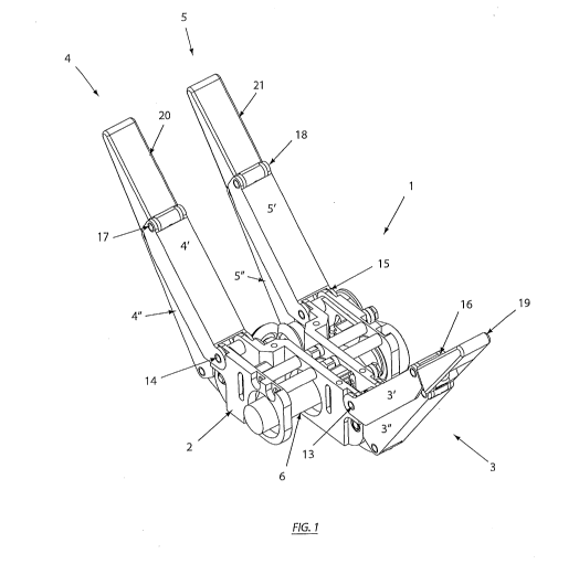
With reference first to figure 1 and figure 2, the
artificial hand of the invention is indicated with reference
numeral 1. Figure 1 shows that the artificial hand 1 is embodied
with a frame 2, and further. that it has a thumb 3 and in the
shown case also two fingers 4, 5.
Figure 1 and more clearly figure 2 show that the
artificial hand 1 has a motor drive 6 which is used for
adjusting the thumb 3 and fingers 4, 5.
In accordance with the invention figure 2 and more
clearly figure 3 show that the motor drive 6 has a housing 7 and
an axle 8. The axle 8 is in a known manner rotatably positioned
within the housing 7. According to the invention however the
housing 7 is mounted in a first bearing 9' that is supported by
the frame 2, which enables that the housing 7 can rotate with
respect to the frame 2. Likewise the axle 8 is mounted in a
second bearing 9" that is also supported by the frame 2. The
load of the motor drive 6 with respect to the frame 2 is thus
evenly distributed.
Figure 2 and figure 3 further show that the thumb 3 and
fingers 4, 5 are drivingly connected with the housing 7 and the
axle 8 respectively by means of the belts 7' and 8'.
CA 02766998 2011-12-29
WO 2011/005085 PCT/NL2010/050427
4
With reference further to figure 3 which shows the
drivetrain without the driven thumb 3 and fingers 4, 5, it is
shown that the fingers 4, 5 have drive axles 10, 11 that are
positioned coaxially and in line with each other, with an
interpositioned differential 16 to allow that a driving torque
from the motor drive 6 is distributed to the respective fingers
4, 5 in accordance with the loads experienced by the said
fingers 4, 5 during use of the artificial hand 1 of the
invention.
The said drive axles 10, 11 are preferably embodied as
hollow tubes that accommodate a central shaft that is rotatably
positioned therein and that supports a planetary wheel 16' of
the differential 16. The differential 16 per se thus can be
embodied without housing.
With reference again to figures 1 and 2 it is shown that
the thumb 3 and fingers 4, 5 are connected to the frame 2 with
hinges 13, 14, 15. As can be best seen in figure 2 the thumb 3
and fingers 4, 5 are drivingly connected with their respective
driving axles 10, 11, 12 through rack-and-pinion drives that are
placed eccentric with respect to the hinges 13, 14, 15. A good
view at the rack-and-pinion drive of finger 5 is shown in figure
4, and is indicated with arrow A showing that this drive is
eccentric with respect to the hinge 15.
It is further remarked that in a particular aspect of
the invention both the thumb 3 and the respective fingers 4, 5
comprise two U-bars 3', 3", 4', 4", 5', 5" (see figure 1). The
open faces of said U-bars face each other so as to embody the
thumb and fingers as a complete enclosure of an inner void. To
this end the legs of the U-bars 3", 4", 5" fit between the legs
of the cooperating U-bars 3', 4', 5'.
With this construction the two cooperating U-bars 3',
3", 4', 4", 5', 5" embody a first set of the opposite links of a
four-bar mechanism, whereby a first of the remaining links is
near the connection provided by the hinges 13, 14, 15 of the U-
bars to the frame 2, and is formed by the racks 22, 23, and 24
(see figure 2) of the concerning rack-and-pinion drives of the
thumb 3, and fingers 4, 5. A second of the remaining links is at
the joint 16, 17, 18 of the said U-bars 3', 3", 4', 4", 5', 5"
and is formed by the phalanges 19, 20, 21 of the thumb 3 and
CA 02766998 2011-12-29
WO 2011/005085 PCT/NL2010/050427
fingers 4, 5 distant from the frame 2. This is clearly shown in
figure 1.
It is expressly remarked that the above given
elucidation with reference to the drawing is not limiting the
5 appended claims, and that this elucidation is only intended to
remove any possible ambiguity that may exist in the wording of
the claims.