Note: Descriptions are shown in the official language in which they were submitted.
CA 02767010 2015-07-13
BONE REPAIR SYSTEM AND METHOD
TECHNICAL FIELD
This invention relates to a system and method for the repair of fractured
or broken bones, such as ribs.
BACKGROUND
A flail chest is a condition that occurs when multiple adjacent ribs are
broken, separating a segment of the chest wall so that it becomes detached
from the
rest of the chest wall and moves independently therefrom. This detached
segment
moves in the opposite direction as the rest of the chest wall, moving inward
while the
rest of the chest is moving outward and vice versa, creating "paradoxical
motion" that
increases the effort and pain involved in breathing.
Most rib fractures are treated conservatively using pain management
and/or bracing techniques. Fractured ribs in a flail chest treated in such a
manner may
undergo progressive displacement during the healing phase, resulting in
considerable
deformity, volume loss, atelectasis, and chronic pain. Long-term problems of
patients
with flail chest injuries treated nonoperatively include subjective chest
tightness,
thoracic cage pain, and dyspnea.
Four categories of fixation devices for operative chest wall fixation
have been utilized, namely plates, intramedullary devices, vertical bridging,
and
-1-
CA 02767010 2011-12-29
WO 2011/002882
PCT/US2010/040596
wiring. The results of these repair techniques are often less than desirable
because of
the difficulty in correctly locating the broken rib ends with one another.
Stabilizing
rib fractures is challenging because large incisions are typically needed to
accommodate fixation, which leads to a more morbid procedure. In addition,
ribs are
narrow with a thin cortex that surrounds soft marrow, making reliable fixation
problematic under conditions that include upwards of 25,000 breathing cycles
per day,
as well as coughing. Still further, there is risk of damage to the
neurovascular bundle.
Currently, the surgery involves a significant operative procedure with
mobilization of large chest wall flaps or open thoracotomy. The problems and
risks
of an operative approach include the surgical trauma itself and the loosening
and
migration of implants. The surgery involves a major incision through the
muscle
directly down to the ribs, which can have complications such as loss of muscle
function, blood loss, and damage to surrounding vascular and neural tissue.
The ribs
that are to be fixed need to be adequately exposed in order to obtain a good
placement
of metal fixation plates. A wide incision is performed, and myocutaneous flaps
may
need to be raised to allow visualization of all segments. Posterior injuries
are usually
challenging due to the presence and required exposure of large muscle fibers
(e.g.,
latissimus dorsi, trapezius, rhomboids, paraspinous muscles). The procedure
utilized
in current practice is typically at least three hours in length with an
additional hour
required for the closing of the surgical exposure.
BRIEF DESCRIPTION OF THE DRAWINGS
FIGURE 1 is a perspective view of a trocar in accordance with an
aspect of the present invention;
FIGURE 2 is a schematic representation of the trocar engaged with a
patient's rib;
FIGURE 3 is a top plan view of a bone plate in accordance with an
aspect of the present invention;
-2-
CA 02767010 2011-12-29
WO 2011/002882
PCT/US2010/040596
FIGURE 4 is a top plan view of an outer fastener in accordance with
an aspect of the present invention;
FIGURE 5 is a side elevational view of a fastener assembly in
accordance with an aspect of the present invention with a cable passed
therethrough;
FIGURE 6 is a side elevational view of an outer fastener, trocar, and
drive tool in accordance with an aspect of the present invention with a cable
passed
therethrough;
FIGURE 7 is a side elevational view of a bone plate and inner fastener
combined with the components of FIG. 6;
FIGURE 8 is a schematic representation of an alternative fastener
assembly according to an aspect of the present invention;
FIGURE 9 is a side elevational view of a fastener assembly and drive
tool according to another aspect of the present invention with a flexible rod
passed
therethrough;
FIGURE 10 is a side elevational view of the drive tool engaged with
the outer fastener;
FIGURE 11 is a side elevational view of the engaged outer and inner
fasteners and the flexible rod and drive tool removed;
FIGURE 12 is a schematic representation of a trocar in accordance with
the present invention engaged with a patient's rib;
FIGURE 13 is a schematic representation of a drill guide inserted into
the trocar;
-3-
CA 02767010 2011-12-29
WO 2011/002882
PCT/US2010/040596
FIGURE 14 is a schematic representation of rods passed through the
trocar and newly formed holes in the rib;
FIGURE 15 is a schematic representation of a rod being passed through
the rib and back out of the chest cavity;
FIGURE 16 is a schematic representation of the drive tool inserted into
the trocar and the inner fastener and bone plate being passed through the
opposite ends
of the rods into engagement with the internal surface of the rib;
FIGURE 17 is a schematic representation of the inner fastener and
bone plate being secured into position on the rib via tightening of the outer
fastener
with the drive tool;
FIGURE 18 is a schematic representation of the bone plate secured in
position on the internal surface of the rib;
FIGURE 19 is a top plan view of a surgical kit in accordance with an
aspect of the present invention;
FIGURE 20 is a perspective view of a deformable plate component
according to an aspect of the present invention being inserted through the rib
in a
rolled configuration;
FIGURE 21 is a side cross-sectional view of a deformable plate
component inserted through and between two adjacent holes in the rib;
FIGURE 22 is a top plan view of a deformable plate component in a
deployed configuration in accordance with an aspect of the present invention;
FIGURE 23 is an illustration of a composite reinforcing structural
component or patch disposed across a plurality of ribs according to an aspect
of the
present invention;
-4-
CA 02767010 2011-12-29
WO 2011/002882
PCT/US2010/040596
FIGURE 24 is a side elevational view of a patch engaging a rib with
assistance from a pressure applying device such as a balloon in accordance
with an
aspect of the present invention;
FIGURES 25a and 25b are schematic representations of a fastener in
a first position for insertion and second position for deployment,
respectively, in
accordance with an aspect of the present invention;
FIGURE 26 illustrates a fastener engaging a reinforcing member
according to an aspect of the present invention;
FIGURE 27 illustrates another fastener engaging another reinforcing
member according to an aspect of the present invention; and
FIGURE 28 depicts a bone plate with legs for receiving the fastener
therebetween in accordance with another aspect of the present invention.
DETAILED DESCRIPTION
As required, detailed embodiments of the present invention are
disclosed herein; however, it is to be understood that the disclosed
embodiments are
merely exemplary of the invention that may be embodied in various and
alternative
forms. The figures are not necessarily to scale; some features may be
exaggerated or
minimized to show details of particular components. Therefore, specific
structural
and functional details disclosed herein are not to be interpreted as limiting,
but merely
as a representative basis for teaching one skilled in the art to variously
employ the
present invention.
The present invention provides a system and method for repairing
fractured or broken bones, such as ribs. The system and method according to
the
present invention allow bone repair to be performed in a minimally invasive
manner,
thereby lessening patient recovery time. Although the system and method are
shown
and described herein as being applied to the repair of fractured ribs, it is
understood
-5-
CA 02767010 2011-12-29
WO 2011/002882
PCT/US2010/040596
that their application to the repair of other broken bones is fully
contemplated. For
example, the system and method according to the present invention may also be
utilized for the minimally invasive repair of bone segments such as a
fractured
clavicle, fractured tibia, fractured pelvis, fractured spine, or fractured
joint surface
where there are displaced and/or multiple bone fragments that would otherwise
require
a large open surgical exposure to repair.
In overview, in accordance with an aspect of the present invention,
fixation of bone segments such as fractured ribs includes the placement of
tethered
repair components through a percutaneous skin incision down to the bone and
delivery
of repair components into the pleural space. Assistance may be provided by a
video-
thorascope, imaging technologies, or other minimally invasive observation
method.
The tethered repair components include a reinforcing member, such as a bone
plate,
and a fastener assembly, such as a screw and nut or other compressive fastener
assembly, wherein the broken rib segment is stabilized by securing the bone
plate
against the rib with the fastener assembly. The bone plate may be attached to
the rib
on its internal surface, the side of the rib lining the pleural space. The
tether, such as
a cable or rod, serves to facilitate the procedure by guiding and providing
control over
the repair components, and to provide safety and efficiency for the surgeon.
The use of such means of rib fixation according to the present
invention allows for the passage of fastener hardware through the central,
thickest
portion of the rib, thus minimizing the risk of inadvertent damage to the
peripheral
neurovascular anatomy. Further, the rib is a very small bone that typically
has only
a thin cortical shell or, in some cases, is comprised of largely cartilaginous
material.
Thus, a traditional repair utilizing typical bone screws has a significant
chance of the
screw loosening and thus the plate becoming loose over time.
A rib fracture repair can be performed in accordance with an aspect of
the present invention utilizing one or more small (e.g., < 15 mm) percutaneous
incisions. A first incision may be utilized to percutaneously locate and drill
holes for
the passage of fasteners which allow for simultaneous capture and engagement
with
both inner and outer portions of the rib and mechanical interlock with the
reinforcing
-6-
CA 02767010 2011-12-29
WO 2011/002882
PCT/US2010/040596
member. A second incision allows for the percutaneous insertion of fasteners
and
reinforcing members to be placed against the rib via the pleural space. A
third
incision may be utilized to allow for thorascopic visualization of the
fracture site. In
the drawings provided herein, although not shown, it is understood that the
patient's
skin overlies the ribs R and the above-described incisions are made
therethrough.
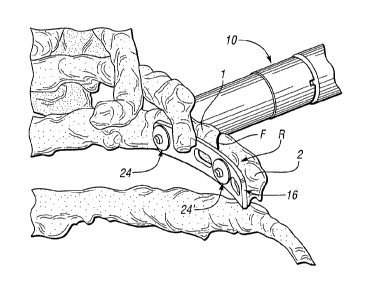
With reference to FIGS. 1 and 2, in accordance with an aspect of the
present invention, a trocar 10 may be percutaneously inserted through a skin
incision
(i.e., the first incision described above; not shown) and placed in contact
with the rib
R. Insertion of the trocar 10 assists in locating the rib R and is used to
facilitate
drilling of a hole through the rib R for affixing the reinforcing member to
the rib R.
The trocar 10 may be generally tubular or have an otherwise hollow
configuration, and
have a length capable of reaching the affected fracture site and engaging the
bone in
a controlled fashion. The trocar 10 may include two spaced spades or
protrusions 12
at the engagement end 14 thereof to help orient the trocar 10 relative to the
affected
bone. The protrusions 12 may orient the trocar 10 centrally over a width of
the rib R
or in a manner such that another specific location on the bone and the long
orientation
of the bone can be positively identified by the surgeon. Further, the
protrusions 12
may actively engage the bone in such a manner as to cause a positive lock to
the bone,
thus maintaining the position of the trocar 10 relative to the bone and
fracture site
throughout the surgery. In one embodiment, the protrusions 12 may be
diametrically
spaced on the trocar engagement end 14.
During the surgical repair, the protrusions 12 may be positioned along
the sides of the rib R as illustrated in FIG. 2, thus generally centering the
trocar 10
over the rib R. Accordingly, the trocar 10 will locate a subsequently inserted
drill
guide generally centrally over the width of the rib R such that the hole
drilled for
receipt of the fastener assembly will be generally located in the center of
the rib R as
measured from side to side. According to an aspect of the present invention, a
navigated trocar may be employed.
Turning to FIG. 3, an exemplary reinforcing member, bone plate 16,
is depicted which may be constructed from an appropriate material such as, but
not
-7-
CA 02767010 2011-12-29
WO 2011/002882
PCT/US2010/040596
limited to, titanium, stainless steel, polymer, ceramic or a bio-resorbable
material or
combinations thereof The bone plate 16 includes at least two openings to
accept a
fastener assembly that allows the bone plate 16 to be securely fastened in
position. In
one embodiment, the bone plate 16 includes a hole 18 at one end at least one
elongated slot 20 at the other end. In accordance with an aspect of the
present
invention, the hole 18 may either be square or have another not-round shape.
The
bone plate 16 can be constructed with any combination of holes 18 and
elongated slots
20 for achieving the desired stability. With reference to FIG. 18, a non-
limiting
example includes a single hole 18 and three elongated slots 20. Providing a
bone plate
16 with one or more elongated slots 20 allows the hole locations in the bone
to be
more flexible along each slot 20 for bone plate location, thus less precision
is required.
This is especially beneficial when positioning a bone plate 16 along the more
curved
elements of the ribs.
For the type of repair described herein, according to one non-limiting
aspect of the present invention, the bone plate 16 may be approximately 2-20
mm in
width, or more particularly 8-12 mm in width. The length of the bone plate 16
is as
needed, but according to one non-limiting aspect of the present invention may
range
from 40-400 mm. The thickness of the bone plate 16 can be uniform or variable,
such
as providing greater thickness near the middle of the bone plate 16 to enhance
stiffness
or to tailor the stiffness to a specific level, such as to match the
particular section of
the rib bone. According to one non-limiting aspect of the present invention,
bone
plate thickness may range from 0.25-4 mm. The bone plate 16 may be generally
linear
or may include angled portions (FIG. 19). Of course, it is understood that the
bone
plates 16 described herein may have any shape and are not limited to any of
the above
dimensions, and may instead appear as cables, rods, or other shapes.
The bone plate 16 may be generally planar, or may instead be curved
(FIG. 19). The bone plate 16 can be curved in a planar fashion or twisted in a
non-
planar, curvilinear fashion in order to conform to the more difficult shapes
of certain
ribs, such as those found in the most anterior and posterior portions of the
rib cage.
Curvature desired of the bone plate 16 can be based on CT or other noninvasive
diagnostic imaging techniques, or through physical measurement of the rib cage
at the
-8-
CA 02767010 2011-12-29
WO 2011/002882
PCT/US2010/040596
time of surgery. Curvature in the bone plate 16 can be established at the time
of
manufacture, thus providing a library of shapes appropriate to the approximate
shape(s) of the rib(s) to be repaired, or the bone plate 16 could be custom
bent at the
time of the surgery in the operating room.
In one embodiment, a CT of the patient's rib cage may be performed
prior to surgery. The CT data may then be fed into a specially designed
analytical
software program, wherein the ideal shape of the bone plate 16 may be
determined
based on the shape of the existing healthy portions of the patient's rib cage
and
anatomical atlases. A determination may be made, with a combination of this
analytical software and surgeon input, to establish the ideal shape of the
bone plate 16
required to repair the fracture site. A computer-controlled bending or
template
machine can be utilized to mold or shape an existing generically sized bone
plate 16
into a specific patient-matched plate, prior to or at the time of the surgery,
thereby
minimizing the time required to complete the surgical repair.
According to an aspect of the present invention, the bone plate 16 can
be coated with a substance to assist in reducing inflammation. According to
another
aspect of the present invention, an adhesive may be applied to the bone plate
16 to
adhere it permanently or temporarily to the rib.
With reference to FIGS. 4 and 5, first, or outer 22, and second, or inner
24, fasteners according to an aspect of the present invention are shown,
wherein the
outer and inner fasteners 22, 24 each include a longitudinal channel (not
shown) in
order to receive a tether, such as a cable or rod, therethrough. Outer and
inner
fasteners 22, 24 engage to form a fastener assembly that secures the bone
plate 16 to
the rib. In one embodiment, the outer fastener 22 may be a threaded screw and
the
inner fastener 24 may be a nut, although it is understood that other fasteners
are also
contemplated. For example, fasteners such as screws with machine threads,
tapered
threads, rivets, adhesively joined, and other such positive engagement type
fasteners
may be utilized.
-9-
CA 02767010 2011-12-29
WO 2011/002882
PCT/US2010/040596
The inner fastener 24, which resides in the pleural space, may have a
portion, such as shoulder 26, shaped to facilitate engagement with and prevent
rotation
of the fastener assembly when engaging the holes 18 or slots 20 of the bone
plate 16.
In one embodiment, a square or other non-round shaped shoulder 26 may be used.
Such a configuration is beneficial since the surgeon may not have direct
physical
access to the inner fastener 24 in order to hold the inner fastener 24
securely while
tightening the outer fastener 22 as described below. The inner fastener 24 may
also
be engaged mechanically to the bone plate 16 prior to its insertion. The outer
fastener
22 may include an engagement port 28 for engagement by a drive tool 30 (FIG.
6) to
accomplish tightening of the engaged fastener assembly. Of course, it is also
contemplated that a drive tool could be configured to be inserted into the
pleural space
and engage with and tighten the inner fastener 24, or that the outer fastener
22 could
include a shoulder as described above.
As shown in FIGS. 5-7, each of the fastener assembly 22, 24, the trocar
10, the drive tool 30, and the bone plate 16 are configured to have a tether
or guide
member, such as a cable 32, passed therethrough, wherein the cable 32 also
passes
through a hole drilled in the bone in order to locate and guide the bone plate
16 and
fasteners 22, 24. In one embodiment, each cable 32 or other tether may be
colored or
have another identifying feature, and may include a secure grommet 34 at its
proximal
33 and distal 35 ends to maintain control of the location of the repair
components.
Instead of a cable 32, a flexible rod 36, such as made of plastic or
metal, may be used as depicted in FIGS. 9-11. The rod 36 may be used to pass
through inner and outer fasteners 22, 24 and the drive tool 30 as shown in
FIG. 9,
along with passing through the other components and the drilled bone,
performing a
guide function for the repair components as with the cable 32 described above.
Rod
36 includes proximal 37 and distal 39 ends, wherein a distal end 39 of the rod
36 may
be threaded or utilize other mechanical means for securing the inner fastener
24
thereto. Of course, it is understood that grommets 34 could be instead used
with the
rods 36, and that the cable distal end 35 could instead be threaded. Along the
flexible
rod 36, the drive tool 30 engages the outer fastener 22 (FIG. 10) and tightens
it to the
inner fastener 24 (FIG. 11). If further safety is desired, the rod 36 can also
be made
-10-
CA 02767010 2011-12-29
WO 2011/002882
PCT/US2010/040596
hollow to accept a centrally located wire or cable in case the rod 36 fails.
Use of a
larger diameter flexible rod 36, as compared with a cable 32, may allow the
surgeon
to exert more tensile force on the bone plate 16 and fastener assembly 22, 24
without
undo risk of breakage. A portion of the rod 36 may also be used as an integral
portion
of the final fastener assembly.
In another embodiment, a snare-type tether may be used that can loop
or otherwise engage the reinforcing member 16 to facilitate locating the
reinforcing
member 16 against the rib. Such a snare-type tether can also act as both as a
fastener
and guidance mechanism, such that it is contemplated that the inner fastener
24 could
be eliminated. In addition, the tether distal end may mechanically engage the
reinforcing member 16 for pulling the reinforcing member 16 into the body and
securing to a fastener, such as with a bayonet connection.
In accordance with another aspect of the present invention, an
alternative to the threaded fastener assembly is the use of an inner fastener
comprising
a grooved member 38, inserted through the bone from the inside as depicted in
FIG.
8. While under location and tensile control by the cable 32 or rod 36, an
outer fastener
comprising a rapid connecting ratcheting nut 40 may be pushed down over the
grooved member 38. In this embodiment, the nut motion is only vertical
relative to
the bone plate 16, thus measures for preventing fastener rotation are
unnecessary. The
underside of the nut 40 may have a concave shape such that it has a more
intimate fit
with the outer surface of the rib and can distribute the compressive loads of
the nut 40
more evenly to the rib.
In a further variation, a fastener assembly may be utilized that is
adhesively bonded together while under compressive loading, applied from a
tool
capable of pulling the inner fastener 24 and bone plate 16 together with the
outer
fastener 22. While holding the assembly under the compressive loading, thus
securing
the bone plate 16 to the rib, an adhesive may be applied either alongside the
cable 32
or from within a hollow core of the rod 36. Once the adhesive is set, the
cable 32 or
rod 36 can be removed, provided they are coated with a release or non-stick
coating.
-11-
CA 02767010 2011-12-29
WO 2011/002882
PCT/US2010/040596
If such a coating is not provided, the cable 32 or rod 36 can be cut off, such
as near the
top of the outer fastener 22.
Simultaneous with the adhesive approach, or in combination with the
all-mechanical approach of the fastener assembly, the hollow rod 36 or
fastener
assembly 22, 24 could be used to deliver bone cement to the fracture site
while the
fracture is in a reduced state. The fastener assembly could be removed upon
setting
of the bone cement or be left in place. If the fastener assembly is made of
bio-
resorbable materials, the fastener assembly could be left in place to resorb
over a
period of time, ultimately leaving no sign of the original fracture repair.
With reference now to FIGS. 12-18, a method for repair of a bone
fracture F in accordance with the present invention will be described wherein
a first
bone segment 1 is fixed to a second bone segment 2. The fracture site to be
repaired
may be initially identified radiographically or via ultrasound and, at the
time of
surgery, through video-assisted viewing through a thorascope (not shown). The
site
may be palpated externally and confirmed internally to identify the size and
location
of the fracture and any displacement of the rib segments. A percutaneous
incision
(e.g., the first incision described above) may be made directly over an
intact, stable
portion of the rib followed with a blunt dissection of the tissue down to the
bone itself.
As shown in FIG. 12, according to an aspect of the present invention, the
trocar 10
may be used to locate the rib R by passing the trocar 10 through the soft
tissue down
to the bone. The trocar 10 may be positioned generally centrally over the rib
by
assuring that the protrusions 12 are positioned along the sides of the rib R.
The trocar
10 may also actively engage the bone in such a manner as to cause a positive
lock to
the bone, thus maintaining the position of the trocar relative to the bone and
fracture
site throughout the surgery.
Referring to FIG. 13, according to an aspect of the present invention,
a drill guide 42 may be placed inside the trocar 10 and used to facilitate the
drilling
of a hole through the bone, wherein the hole will receive the fastener
assembly 22, 24.
In one embodiment, a drill, such as a cannulated wire drill, may be used to
facilitate
passage of the cable 32 or flexible rod 36 through the rib R to the other side
of the
-12-
CA 02767010 2011-12-29
WO 2011/002882
PCT/US2010/040596
fractured bone. In some situations, the rod 36 or cable 32 may be passed
through the
drilled hole on its own after removal of the drill. Drilling may occur under
direct
visualization using a thorascope. Furthermore, utilization of fluoroscopy or
another
real-time imaging method may aid the surgeon in locating, repositioning and
fixing
in place the displaced rib segments.
As shown in FIG. 14, according to an aspect of the present invention,
the rod 36 (or cable 32 or other tether) is passed through the drill guide 42,
and
through the created hole in the rib R and into the pleural space. A first rod
36 and a
second rod 36' are depicted. The entrance into the pleural space may be
visualized
with a video thorascope. The cable or rod distal end 35, 39 is grabbed, such
as with
a grasping instrument (not shown), and withdrawn through the second incision
referenced above and outside of the chest cavity (FIG. 15). As an alternative,
the
threaded rod or cable may be externally guided such that its placement and
path
through the pleural space can be entirely guided by the surgeon without the
need for
thorascopic instruments to grab them from the inside, similar to the manner in
which
an endoscope is manipulated. This externally guided rod or cable assembly can
also
have the video guidance built into it, thus eliminating any need for a
thorascopic
incision port (i.e., the third incision referenced above). At this point in
the surgery,
both the proximal 33, 37 and distal 35, 39 ends of the cable 32 or rod 36 are
visible
from outside of the patient's body.
Once inserted through the rib, both the cable 32 and the threaded rod
36 can also be used to reduce the fracture through mechanical manipulation of
the
bone ends. The surgeon is able to pull on the displaced bone directly from
outside of
the chest cavity without the need for a larger exposure while simultaneously
aligning
the bone plate 16 and fasteners 22, 24 into final position. While applying
such
correcting force, the surgeon is able to tighten or otherwise fasten the bone
plate 16
into its final corrective position. Since the method according to the present
invention
allows for access to both sides of the rib simultaneously, in certain
circumstances it
may also be desirable to pass a tether, such as a cable, from one drilled rib
hole to
another in order to pull the bones together. In this instance, a grommet or
other stop
can be placed on the proximal or distal end of the tether to prevent the
tether from
-13-
CA 02767010 2011-12-29
WO 2011/002882
PCT/US2010/040596
pulling through the holes when force is applied to the end of the tether
opposite the
stop.
FIG. 16 illustrates placement of the bone plate 16 and first and second
inner fasteners 24, 24' onto the first and second flexible rods 36, 36',
respectively, in
accordance with an aspect of the present invention. When a cable 32 is used,
once the
cable 32 is drawn through the abdominal wall, the bone plate 16 may first be
passed
over the cable distal end 35 followed by the inner fastener 24. A grommet 34
(or a
wire button or the like) may be used to secure the distal end 35, wherein the
grommet
34 should be large enough to prevent the bone plate 16 and inner fastener 24
from
becoming disengaged from the cable 32. When a rod 36 is used, once the rod 36
is
drawn through the abdominal wall, the bone plate 16 may first be passed over
the rod
distal end 39. The inner fastener 24 may then be threaded or otherwise secured
onto
the distal end 39 for positive control over the bone plate 16 and fastener
assembly.
Once the repair components have been secured to the cable 32 or rod 36, the
components are ready to be drawn back into the thoracic cavity for placement
against
the desired rib segment pulled and guided by the cable 32/rod 36.
The procedure may be repeated for subsequent drilled holes, typically
on the other side of the bone fracture F, wherein a differently identifiable
(e.g., color
or other means of identification) cable 32 or rod 36 may be used in order to
identify
the particular location through the rib R. As described above, the bone plate
16 may
include one or more elongated slots 20 through which additional cables 32/rods
36
may be passed. An initial distance measurement between drilled points on the
bone
may be made of the external (e.g., first) incision points. That distance may
be further
confirmed by the use of a thorascopically deployed measuring instrument so
that the
inner distance between holes can be made. This measurement provides
information
as to the curvilinear and/or straight configuration of the rib cage, and
provides the
surgeon with an accurate assessment of the relative drilled bone position once
the
fracture site has been properly reduced. The use of a combination of holes 18
and
slots 20 on the bone plate 16 reduces the need for exact hole placement on the
rib by
the surgeon, as the final position of the fasteners 22, 24 on the bone plate
16 is
adjustable due to use of the slots 20. This configuration accommodates
imprecise
-14-
CA 02767010 2011-12-29
WO 2011/002882
PCT/US2010/040596
drilled hole and fastener placement through the rib.
Once the desired number of cables 32/rods 36 has been brought out
through the instrument port (e.g., second incision), the bone plate 16 may be
fed onto
the cables 32/rods 36 in the proper orientation. In one embodiment, the end of
the
bone plate 16 where the single square hole 18 is located may be utilized
against the
stable rib portion. The bone plate 16 and inner fastener 24 may then be drawn
into the
chest cavity and pleural space and, with possible video and thorascopic
assistance, the
bone plate 16 may be positioned near the site of the rib fracture to be
repaired while
the cables 32/rods 36 are slowly drawn through the drilled holes in the rib R
as
illustrated in FIG. 17. The use of two or more cable or rod assemblies at one
time will
assure the proper orientation of the plate and fastener assemblies once pulled
back into
and against the internal surface of the chest cavity.
In accordance with an aspect of the present invention, once the drill
guide 42 is removed from the trocar 10, the outer fastener 22 may be moved
into
position along the cable 32/rod 36 through the drilled hole into the bone,
into
engagement with the inner fastener 24, and secured thereto with the drive tool
30
(FIG. 18). In one embodiment, the fastener assembly 22, 24 inserted through
the hole
18 of the bone plate 16 may be tightened first, followed by the fastener
assembly 22,
24 inserted through the slot 20 since less alignment between the rib hole and
bone
plate opening is required with the slot configuration. Tension may be applied
to the
cable 32/ rod 36 by the surgeon, thus drawing the inner fastener 24 into
position with
the bone. Once the inner fastener 24 engages the bone plate 16, the outer
fastener 22
may be tightened with the drive tool 30 until the desired level of torque and
tightness
has been reached. The drive tool 30 may engage the engagement port 28 of the
outer
fastener 22 in order to rotate the outer fastener 22 and secure it to the
inner fastener
24. In one embodiment, the inner fastener 24 may be prevented from turning by
its
square shoulder 26 engaging in a square hole 18 on the bone plate 16. Of
course,
other methods of securing the outer and inner fasteners 22, 24 together are
also fully
contemplated.
In one embodiment, a washer (not shown) may be used under the outer
-15-
CA 02767010 2011-12-29
WO 2011/002882
PCT/US2010/040596
fastener 22 to aid in distributing the load between the outer fastener 22 and
the bone.
The washer may be concave shaped (on the bone-mating side), oriented to fit
saddle-
like over the rib, to attempt to further reduce localized stresses on the
bone. The
washer may also be enhanced with a deformable component to reduce the
localized
bone stresses even further.
If repositioning of the rib segment is required to reduce the fracture,
then the use of a device, such as a gimlet, can be used to help facilitate the
relocation
of the broken segment while the fastener assemblies 22, 24 are tightened. The
cable
32 or rod 36 can also can act to facilitate alignment of bone segments for
reduction of
the fracture site, since the bone segment can be pulled with the cable 32 or
rod 36 and
re-located as required once the inner fastener 24 and the bone plate 16 are
engaged
with the inner side of the bone. In addition to the use of the cable 32 or rod
36 to
facilitate reduction of the fracture site, a pressure applying device, such as
a balloon,
can be used as part of the thorascope assembly or in conjunction with it to
apply
pressure against the pleura, and thus the ribs, and position them into a
conforming
shape. This will help reduce the fractured ribs if necessary, and hold the
ribs in that
position until the fasteners 22, 24 are tightened.
Once all of the fastener assemblies 22, 24 are tightened and the surgeon
is comfortable with the location, tightness, stability and other parameters
such as
reduced position of the bones, the rod 36 may be unscrewed or otherwise
detached
from the inner fastener 24 and removed, thus completing the repair. In the
case of the
cable 32, the grommet 34 on either end 33, 35 may be cut and the cable 32
withdrawn
from the chest cavity. Standard layer closure utilizing resorbable sutures
followed by
a local rib block (e.g., with Marcaine) may be used to complete the surgical
steps.
Visual and tactile feedback of the repair should be considered sufficient, and
the
procedure may then be repeated for other drilled locations.
According to an aspect of the present invention, the bone plate 16 may
be part of a system including components that are flexible or deformable, such
that the
components can be delivered or deployed into the body or working location in a
first
configuration, and then change configuration, either actively or passively,
into a
-16-
CA 02767010 2011-12-29
WO 2011/002882
PCT/US2010/040596
second configuration once inserted into the pleural space. These components
may
include, for example, plates, washers, cables, wires, fasteners, or parts of
these
components. A deformable plate component may be longitudinally rolled, coiled,
or
compressed in preparation for delivery and then wholly or partially deployed
or
manipulated while inside the pleural space. The components may be partially
deployed so that part of the component may assume one function while another
part
may serve another function. The deformable components may be steered, guided,
or
directed into a shape, location, or configuration as part of the fixation
system in
accordance with the present invention.
In one embodiment, a deformable plate component 16 may be inserted
while in a first configuration, such as a rolled shape, into one drilled rib
hole (FIG.
20), into the pleural space and then fed back out, across the fracture area F,
and out of
the pleural space through another drilled rib hole (FIG. 21). The area of the
bone plate
16 between the holes on the pleural side may then be at least partially
deployed into
a second configuration, such as a non-round shape (FIG. 22). The end portions
17, 19
of the deformable plate 16 that pass through the rib may still be maintained
in their
original round shape and secured in place while under tension with an
appropriate
fastener 22, such as a unidirectional push lock. The ends 17, 19 of the
deformable
plate 16 may then be trimmed to the appropriate length.
Bone plates 16 can be additive to affect their length. For example, the
bone plate 16 may be a smaller, individual portion of a modular system of
coupling
or interlocking bone plates that, once inserted and placed into general
position, can be
locked into final position through the tightening of fasteners 22 and 24. In
one
embodiment, the ends of one plate can engage with the next plate in line, such
as in
an overlapped toothed fashion, thus allowing for shaping of the plate while it
is
already in the pleural space and providing for more accurate final positioning
by the
surgeon.
In one embodiment, the bone plate 16 may be made of a reinforcing
mesh or fabric of fibers combined with a resin matrix to form a composite
reinforcing
structural component or patch 44 as illustrated in FIG. 23. This patch 44 can
be
-17-
CA 02767010 2011-12-29
WO 2011/002882
PCT/US2010/040596
applied to the general area of the fracture F, extending beyond the fracture
area to
areas of non-fracture. Further, the patch 44 can be simultaneously applied
across
several spaced apart ribs R at one time as shown, thus allowing for a single
reinforcing
member for a multiple rib fracture site. The composite patch 44 can be joined
adhesively to the pleural side of the repair across the entire surface, can be
joined
mechanically to the ribs, or a combination of both joining methods. The patch
44 can
be supplied, while in an uncured or otherwise pliable state, to the pleural
space in one
shape for initial engagement of the bone segment, and then delivered and
placed into
final position, cured, bonded, or otherwise fastened to the pleural underside
of the ribs.
As an example of the above, a deformable patch 44 may be rolled,
coiled, or compressed in preparation for delivery and then wholly or partially
deployed
or manipulated while inside the pleural space. Prior to curing or bonding to
the
pleura, the patch may further be steered, guided, or directed into a shape,
location, or
configuration as part of the fixation system according to the present
invention. The
patch may be positioned into correct placement with external manipulation via
the
aforementioned cables 32 or rods 36, or entirely through a thorascopic-only
assisted
and directed placement. In the example of thorascopic-only assisted and
directed
placement, a pressure applying device 46, such as a balloon, can be used as
part of the
thorascope assembly or in conjunction with it. As shown in FIG. 24, the
pressure
applying device 46 may be used to deploy the patch 44 against the pleura,
position it
into a conforming shape, reduce the fractured ribs if necessary, and hold the
patch 44
in that position until the patch 44 is cured. In this manner, the patch 44 may
either be
adhesively bonded to the pleural lining and, if necessary, additionally
mechanically
attached to the ribs via the aforementioned fasteners and fastening methods.
The
pressure applying device 46 and thorascope (not shown) may then be removed and
the
repair will be complete.
As a primary means of fixation or if additional fasteners are desired,
they can be added through the aforementioned means. Alternatively, with the
bone
plate 16 in the correct position and at least partially secured in place,
additional
fasteners may be placed through the bone plate 16 via the inside of the chest
cavity by
using an internally deployed drilling instrument that passes a drill, cable,
rod or other
-18-
CA 02767010 2011-12-29
WO 2011/002882
PCT/US2010/040596
tethering method through to the external portion of the rib cage. The
fasteners used
via such a reversed method can be similar to those fasteners described
earlier.
Alternatively, the fasteners can be of a blind type such that once the drill,
cable or rod
36 is passed through the rib to the outside with the fastener 48 housed
therein for
insertion (FIG. 25a), the fastener 48 can be externally pushed, internally
pulled down,
or otherwise deployed (FIG. 25b) through the rib, through the bone plate 16
and
through the application of outward tension, engage the plate 16 through the
deployment of wings, hooks, arms or any other positive engagement means with
the
bone plate 16 (FIGS. 26 and 27) and secured in place by applying a counter
locking
mechanism, such as a push nut or threaded nut against the external portion of
the rib
bone (not shown). FIG. 26 depicts a fastener 48 engaging a cable or rod type
reinforcing member 16, while FIG. 27 depicts a fastener 48 engaging a bone
plate 16
which includes areas 50 for receiving the fasteners 48. In another embodiment
illustrated in FIG. 28, the bone plate 16 may have legs 52 and the fastener 48
may be
received and interlock between the legs 52, wherein the legs 52 may also have
tabs for
bone anchoring.
Any or all of the components described herein for completing the bone
repair in accordance with an aspect of the present invention can be assembled
for ease
of use as a surgical kit as shown in FIG. 19. A tray can be provided where the
components can be conveniently and securely positioned for ease of access and
use
during a surgery.
The system and method described herein allow for the rapid fixation
of broken rib segments with minimal blood loss (e.g., a reduction of 80-90%),
required surgical time (e.g., a reduction of 50-75%), and reduced post-
operative pain
and discomfort for the patient. Disruption of the surrounding musculature,
soft tissue,
cartilage, periosteum and neural structures is significantly reduced when
compared to
conventional surgical techniques. Once the surgery begins, each repair will
typically
take less than 10 minutes. This differs significantly from the current
techniques which
are quite lengthy, utilize a wide exposure, require large muscle dissection
and often
have a complicated recovery. Patient satisfaction with the repair should be
high due
to the absence of prominent hardware, minimal post-operative recovery time and
the
-19-
CA 02767010 2015-07-13
minimal nature of the incisions.
While exemplary embodiments are described above, it is not intended
that these embodiments describe all possible forms of the invention. Rather,
the
words used in the specification are words of description rather than
limitation, and it
is understood that various changes may be made without departing from the
scope of
the invention. Additionally, the features of various implementing embodiments
may
be combined to form further embodiments of the invention.
-20-