Note: Descriptions are shown in the official language in which they were submitted.
CA 02767217 2012-01-04
WO 2011/005116 PCT/N02010/000279
1
Method and apparatus for CO2 capture
The present invention relates to an apparatus for capturing CO2 from an
exhaust gas
stream and a method therefore.
In the combustion of a fuel, such as coal, oil, gas, peat, waste, etc., in a
combustion
plant, such as those associated with boiler systems for providing steam to a
power plant,
a hot process gas (or flue gas) is generated. Such a flue gas will often
contain, among
other things, carbon dioxide (C02). The negative environmental effects of
releasing
carbon dioxide to the atmosphere have been widely recognised, and have
resulted in the
io development of processes adapted for removing carbon dioxide from the hot
process
gas generated in the combustion of the above mentioned fuels.
The conventional method for removing CO2 from exhaust gas would be by use of a
standard absorption-desorption process illustrated in figure 1. In this
process the exhaust
gas has its pressure boosted by a blower either before or after an indirect or
direct
contact cooler. Then the exhaust gas is fed to an absorption tower where it is
counter-
currently brought into contact with an absorbent flowing downwards. In the top
of the
column a wash section is fitted to remove, essentially with water, remnants of
absorbent
following the exhaust gas from the CO2 removal section. The absorbent rich in
CO2
from the absorber bottom is pumped to the top of the desorption column via a
heat
recovery heat exchanger rendering the rich absorbent pre-heated before
entering the
desorption tower. In the desorption tower the CO2 is stripped by steam moving
up the
tower. Water and absorbent following CO2 over the top is recovered in the
condenser
over the desorber top. Vapour is formed in the reboiler from where the
absorbent lean in
CO2 is pumped via the heat recovery heat exchanger and a cooler to the top of
the
absorption column.
The known processes for removing CO2 from exhaust gas involve equipment that
causes a pressure drop in the exhaust gas. If such a pressure drop is allowed,
it would
cause a pressure build-up in the outlet of the power generating plant or other
plant
generating the exhaust gas. This is undesirable. In the case of a gas turbine
it would lead
CA 02767217 2012-01-04
WO 2011/005116 PCT/N02010/000279
2
to reduced efficiency in the power generating process. To counter this
drawback a costly
exhaust gas blower is needed.
A further problem with existing technology is that the absorption tower and
the
preceding exhaust gas cooler are costly items.
The standard CO2 capture plant also needs a significant area to build upon.
W000/74816 discloses a system for CO2 capture. The system may be arranged as a
horizontal channel where the exhaust gas is brought in contact with two
different
io absorption liquids in two adjacent sections. A screen is included to avoid
liquid to be
transported from one section into the next section. The liquids are being
regenerated and
recalculated.
In the article "Critical flow atomizer in S02 spray scrubbing" by
Bandyopadhyay et al
is (Chemical Engineering Journal 139, pp. 29-41, 2008), it is concluded SO2
removal
efficiency is increased with the increase in liquid flow rate, liquid-to-gas
flow rate ratio,
atomizing air pressure, droplet velocity. The same conclusion is reached by
Srinivasan
et al in the article "Mass transfer to droplets formed by the controlled
breakup of a
cylindrical jet - physical absorption" (Chemical Engineering Science, Vol. 43,
No. 12,
20 pp. 3141-3150, 1988)
The aim of the present invention is to provide a method and apparatus for
removing
CO2 from an exhaust gas stream, where the method provides a reduced pressure
loss,
does not depend on the use of exhaust gas blowers and preferably requires les
energy
25 than the traditional method. Furthermore, it is an aim to provide a
solution which has a
considerably smaller footprint. It is also a goal to provide a solution which
can be
integrated with a new efficient desorption method and apparatus.
A further goal is to provide a system and a method that can be effectively
combined to a
30 plant utilizing recycling of exhaust gas.
CA 02767217 2012-01-04
WO 2011/005116 PCT/N02010/000279
3
It is also intended to provide a system which allows for combination with pre-
treatment
systems for removing other unwanted compounds within the gas stream.
The abovementioned aims and goals are reached by means of a system and method
according to the enclosed independent claims. Further advantageous features
and
embodiments are mentioned in the dependent claims.
The present invention relates to CO2 capture from exhaust gas, and it is a so
called post
combustion technology. The present invention may be utilized in connection
with gases
io coming from different kind of facilities. These facilities could be
combined cycle gas
fired power plants; coal fired power plants, boilers, cement factories,
refineries, heating
furnaces of endothermic processes such as steam reforming of natural gas or
similar
sources of flue gas containing CO2.
A long exhaust channel will be needed in almost all cases of CO2 capture from
exhaust
gas for transporting the gas from the plant generating the gas to the plant
for capturing
CO2. Putting it to good use does not involve extra cost for the exhaust
channel as such.
According to one aspect of the present invention, the necessary contact area
between
gas and liquid is provided by spraying liquid droplets into the gas in the
exhaust gas
channel itself thus eliminating the absorption tower. The direct contact
cooler normally
preceding this tower may also be replaced by doing the same contacting in a
section in
the channel itself.
It is an aim of the present invention to exploit a part of an exhaust gas
channel that is
needed anyway to transport the exhaust gas to the CO2 capture plant. It is not
normally
space to build the CO2 capture plant back-to-back with the power plant. In so
doing, the
conventional DCC and absorption column are eliminated. This exploitation
represents a
very significant cost saving.
The channel is expected to be essentially horizontal, but it could have an
angle between
0 and 60 . The direction of the slope can go either way, and the direction of
the slope
CA 02767217 2012-01-04
WO 2011/005116 PCT/N02010/000279
4
may change along the path of the channel. The channel may also change
direction one
or several times, from 1 to 360 degrees.
The present invention reduces both capital cost and saves energy.
According to one embodiment of the present invention, nozzles direct the spray
mainly
in the flow direction of the exhaust gas thus pushing the gas along in the
channel. The
kinetic energy from the droplets thus imparted on the gas more than overcomes
the gas
pressure drop in the channel. This means that the upstream channel(s) can be
operated at
to a lower absolute pressure. A consequence of this is that the exit pressure
from the
upstream gas turbine (when applicable) may operate at a reduced pressure
compared to
the standard technology, and this reduced pressure at gas turbine exit
increases the gas
turbine efficiency leading to a higher power production.
It reduces the capital cost, saves energy, and may even lead to increased
energy
production from the gas turbine.
These and other objectives are reached by the method according to claim 1 and
an
apparatus according to claim 6. Other benefits and advantageous embodiments
are set
out in the dependent claims.
The present invention will be described in more detail with reference to the
enclosed
figures; wherein:
Figure 1 illustrates a conventional absorption-desorption process;
Figure 2 illustrates a flow sheet of an embodiment of the present invention;
Figure 3 illustrates an embodiment where the channel includes direct contact
cooling
and a washing section;
Figure 4 shows the operating and equilibrium lines for the CO2 absorption
process
shown in figure 3;
3o Figure 5 illustrates an embodiment with an integrated pre-treatment
section;
Figure 6 illustrates the embodiment with exhaust gas recycling; and
CA 02767217 2012-01-04
WO 2011/005116 PCT/N02010/000279
Figure 7 shows a cross-section showing the relative velocity of the internal
circulation
pattern developed in a liquid drop moving in gas.
Figure 1 shows a conventional method for removing CO2 from exhaust gas using a
5 standard absorption-desorption process. In this process the exhaust gas P 10
has its
pressure boosted by a blower P21 either before (as illustrated) or after an
indirect or
direct contact cooler P20. Then the exhaust gas is fed to an absorption tower
P22 where
it is contacted counter-currently with an absorbent P40 flowing downwards. In
the top
of the column a wash section is fitted to remove, essentially with water,
remnants of
io absorbent following the exhaust gas from the CO2 removal section. Washing
liquid P41
is entered at the top and redrawn further down as P42. The CO2 depleted
exhaust gas is
removed over the top as P12. The absorbent rich in CO2 P32 from the absorber
bottom
is pumped to the top of the desorption column P30 via a heat recovery heat
exchanger
P28 rendering the rich absorbent P36 pre-heated before entering the desorption
tower
is P30. In the desorption tower the CO2 is stripped by steam moving up the
tower. Water
and absorbent following CO2 over the top is recovered in the condenser P33
over the
desorber top. Vapour is formed in the reboiler P31 from where the absorbent
lean in
CO2 P38 is pumped via the heat recovery heat exchanger P28 and a cooler P29 to
the
top of the absorption column P22. Steam is supplied to the reboiler as stream
P61. The
20 isolated CO2 leaves as stream P14.
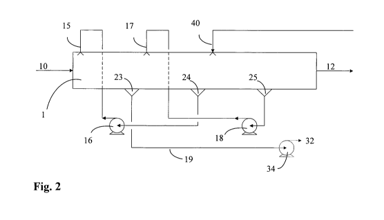
Figure 2 illustrates the main fluid flows of an embodiment of the present
invention.
Exhaust gas 10 enters the channel 1 at one end. Absorption liquid comprising a
CO2
absorbent and a diluent is sprayed into the channel from a nozzle arrangement
15. The
25 absorption liquid is sprayed mainly in the flow direction of the exhaust
gas and with a
speed high enough to at least compensate for the pressure loss in the first
part of the
channel. The droplets of absorption liquid moves trough the exhaust gas stream
and
absorbs CO2 there from. The CO2 rich absorption liquid is collected upstream
at
collection point 23 at the lower part of the channel. The droplets are
collected by the use
30 of an demister/droplet catcher. The CO2 rich absorption liquid 19 is pumped
via pump
34 into conduit 32 connected to a desorption plant. The desorption plant may
be a
traditional desorption plant as illustrated in figure 1 or it can be any other
system for
CA 02767217 2012-01-04
WO 2011/005116 PCT/N02010/000279
6
desorbing CO2 from an absorbent liquid. In the embodiment illustrated on
figure 2 the
exhaust gas continues downstream in the channel and a second absorption liquid
is
sprayed into the gas from a nozzle arrangement 17. The absorption liquid is
sprayed
mainly in the flow direction of the exhaust gas and with a speed high enough
to at least
compensate for the pressure loss in this second part of the channel. The
droplets of
absorption liquid move trough the gas stream and absorbs CO2 there from. The
CO2 rich
absorption liquid is collected upstream at collection point 24 at the bottom
of the
channel. The CO2 rich absorption liquid collected at point 24 is pumped via
pump 16 up
to the nozzle arrangement 15. The exhaust gas continues downstream in the
channel and
io lean absorption liquid 40 is sprayed into the gas from a nozzle
arrangement. The
absorption liquid is sprayed mainly in the flow direction of the exhaust gas
and with a
speed high enough to at least compensate for the pressure los in this third
part of the
channel. The droplets of absorption liquid move trough the exhaust gas stream
and
absorb CO2 there from. The CO2 rich absorption liquid is collected upstream at
is collection point 25 at the lower part of the channel. The CO2 rich
absorption liquid
collected at point 25 is pumped via pump 18 up to the nozzle arrangement 17.
The CO2
depleted exhaust gas leaves the channel at the other end as stream 12.
The channel may be horizontal or have an angle of up to 60 degrees. The
channel may
20 further include one or more demisters or similar arrangement to collect the
droplets of
absorption liquid. The droplets will then be introduced at a speed large
enough to push
the gas stream forward through the demisters.
Figure 2 illustrates the basic configuration of cross-flow treatment in the
exhaust gas
25 channel. The nozzles in this figure are pointing downwards. This is,
however, only for
convenience of drawing. The intention is to point the nozzles mainly in the
direction of
the gas flow, but other configurations may also be feasible, e.g. an array or
cluster of
nozzles pointing in various directions. More examples could be given.
30 One embodiment of the present invention may be described with reference to
figure 3.
The exhaust gas enters the exhaust gas channel that would normally be void of
process
equipment for the 150-250 meters leading to the conventional CO2 capture
plant. At a
CA 02767217 2012-01-04
WO 2011/005116 PCT/N02010/000279
7
convenient point shortly after entry the exhaust gas is here, in section C,
sprayed with
cooling water to form a direct contact cooler. The cooling water is recycled
except a
possible purge. The recycle is via pump and cooler to a point where this
stream is mixed
with compressed gas in the spray nozzles (atomizing nozzles). Droplets created
in this
section are collected in the downstream droplet catchers.
In another embodiment, the pressure of the cooling water is increased to 5-100
bars,
preferably in the range 5-10 bar, with a pump before it exits through spray
nozzles. The
absorbent liquid may also be introduced to the channel in the same way.
The gas for nozzle spraying is compressed in a compressor common for all
nozzle
batteries that uses atomizing nozzles. In one embodiment, the suction gas is
exhaust gas
conveniently extracted from the channel downstream of the DCC section droplet
catchers.
The cooled exhaust gas now enters CO2 absorption section Al where is contacted
concurrently and cross-currently with the CO2 richest absorbent solution
passing
through the absorption process. The liquid is again sprayed into the channel
via nozzles.
The liquid droplets are captured in the downstream droplet catchers. The rich
absorbent
liquid collected is pumped from the Al section to the desorption process not
further
described here. The liquid absorbent sprayed into section Al is pumped from
section
A2 where there is less CO2 in the exhaust gas and the outlet liquid is thus
less rich in
CO2 than that coming out of the Al section. The operating and equilibrium
lines for the
CO2 removal process are shown in figure 4. Also the A2 section has gas liquid
contact
following the same pattern as in section Al. The liquid to section A2 comes
from
section A3 where the CO2 levels are the lowest in both the exhaust gas and the
liquid.
The absorbent liquid sprayed into section A3 is the lean absorbent coming back
from
the desorption process in a regenerated condition. The droplet catchers
downstream of
section A3 would favourably be designed to do a more rigid droplet capture
than the
other sections since any slippage of absorbent will put a higher demand on the
absorbent recovery section W.
CA 02767217 2012-01-04
WO 2011/005116 PCT/N02010/000279
8
The function of section W is to wash essentially all absorbent carried with
the gas from
section A3 out. This is achieved by circulating essentially water over the
section via a
pump and a cooler. A bleed to recycle caught absorbent and a make-up water
stream
would be applied as convenient to the recycle stream. The potential for
removing
absorbent from the exhaust gas is determined by the concentration of free
absorbent in
the wash liquid, and its temperature. There may a need for more than one such
wash
section, and that may be easily added.
It has been found that the droplet sprays are pushing the gas along the
channel to the
io extent that no exhaust gas blower is needed.
The number of stages needed for CO2 absorption is a trade-off against
absorbent flow.
In principle one stage would be enough if sufficient liquid was circulated,
but this
would imply a lot of liquid. Two stages or more are conceivable. In the
standard
counter-current absorption column it may be shown that 2 to 3 equilibrium
stages would
suffice.
According to one embodiment, the present invention may be combined with a pre-
treatment section and a recycling of exhaust gas. These features are described
in more
detail in figure 5 and 6.
In figure 5, one embodiment of the present invention is shown extended with
exhaust
gas pre-treatment. This is relevant for coal fired power stations and a
variety of
industrial settings where CO2 recovery is needed. The pre-treatment could have
one or
more duties. It could e.g. be a sea water wash where the buffering propertied
of sea
water is exploited to absorb SO2 from the exhaust gas. If this was not done,
SO2 would
react irreversibly with the alkaline absorbent used to catch CO2 thus leading
to a greater
consumption. Such a process could also scrub the exhaust gas for particles.
Both these
functions would typically be required downstream of coal burning. From an
aluminium
melter the exhaust gas might contain HF, and more examples could be given. The
fluid
regeneration in the pre-treatment section could e.g. be a filter to contain
particles. In the
case of SO2 absorption into sea water the best course of action is to have a
bleed where
CA 02767217 2012-01-04
WO 2011/005116 PCT/N02010/000279
9
S02 is piped with sea water as sulphite that would in turn be oxidised to
sulphate in the
sea water, a substance that is already in sea water in abundance.
The pre-treatment section could use the same technologies for nozzles and
droplet
catchers as the other sections.
In figure 6, one embodiment of the present invention is shown integrated with
a pre-
treatment section and combined with an exhaust gas recycle (EGR). The
advantage of
using an EGR is that the volumetric exhaust gas flow is significantly reduced
thus
io enabling a reduction in the cross-sectional area in the gas flow sections
and the higher
CO2 content in the exhaust gas which reduces the capital cost of treatment.
Figure 7 is a cross-section showing the relative velocity of the internal
circulation
pattern developed in a liquid drop moving in gas. The gas motion is in the
horizontal
direction and results in a doughnut shaped, toroid flow known as a Hill's
vortex. The
cause of the internal circulation is the shear force at the surface of the
liquid drop,
created by the gas moving along the surface. It is known that a liquid drop
moving
through a viscous fluid, e.g. gas stream comprising C02, will tend to
circulate internally
due to the shear stress applied at its interface by the ambient fluid. Heat
and mass
transfer are greatly augmented by a reduction of the boundary layer thickness.
Compared to a so-called rigid drop (i.e. a liquid drop with no, or very
little, internal
circulation), the transfer coefficients for a liquid drop with internal
circulation is at least
2-4 times higher.
According to an advantageous embodiment of the present invention, an
absorption
liquid, e.g. amine, is introduced or sprayed into a channel 1 by the use of
atomizing
nozzles 15, 17, 40. A flue gas 10 comprising a gas stream comprising CO2 moves
through the channel 1 with a velocity of 5-15 m/s. The diameter of the flue
gas channel
1 may depend on the amount of flue gas produced by the power plant, cement
factory or
similar, but it will in most cases be between 3 and 10 meters. The flow
conditions in the
flue gas channel will thus be highly turbulent with a Reynolds number >> 100
000.
CA 02767217 2012-01-04
WO 2011/005116 PCT/N02010/000279
The absorption liquid leaves the nozzle or nozzles 15, 17, 40 as small
droplets with a
velocity of 30-120 m/s. It is expected that the droplets will be turbulent for
a short while
after they leave the nozzle, 1-2 seconds. The relative velocity difference
between the
absorption liquid doplets and the flue gas causes high shear stress on the
droplets which
5 will help sustain an internal circulation inside the droplets and possibly
sustain turbulent
conditions inside the droplets. The mass transfer in the region adjacent to
the nozzles
will thus be extremely high.
A major drawback of packed bed absorber is the ability to mass transfer of
C02(g) to
10 C02(aq). The mass transfer rate depends on the gas film thickness and a
corresponding
diffusion. These again depend on flow rates. In packed bed absorbers, laminar
flow will
occur, which results in significantly lower mass transfer of C02(g) to C02(aq)
compared
to turbulent flow conditions. The high turbulence in the channel 1 and the
turbulence/internal circulation in the droplets results in significantly
reduced resistance
to mass transfer. As opposed to conventional methods for absorbing CO2 from a
flue
gas 10, the transport of CO2 from the flue gas 10 into the absorption liquid
droplets will
be much higher due to reduced film thickness and the transport of CO2(aq) is
not
dependent on diffusion, but by convection. The reaction with absorbent will
thus be a
lot faster.
Absorption liquid droplet size can be varied by changing pressure on the
absorption
liquid before the nozzle or nozzles, or by the absorption liquid flow rate
through the
nozzle or nozzles. The size and shape of the nozzle or nozzles will also have
an effect
on the absorption liquid droplet size. The relative difference in velocity
between the
mean gas stream and the mean absorption liquid droplet velocity will also
affect the
droplet size. If the velocity ratio between the mean gas stream velocity and
the mean
absorption liquid droplet velocity is greater than approximately 3 when the
absorption
liquid leaves the absorption liquid introduction means, preferably in the
range of 6-10,
this will help ensure internal circulation in the absorption liquid droplets
introduced in
the CO2 gas stream, and that the Sauter mean diameter of the absorption liquid
droplets
is kept relatively small, preferably on the order of 50 m - 500 m.
CA 02767217 2012-01-04
WO 2011/005116 PCT/N02010/000279
11
The residence or flight time of the absorption liquid droplets through the
channel 1 is
also important. As the absorption liquid droplets moves through the flue gas
channel,
the initial collision between the droplets and the flue gas will contribute
towards further
atomization of the droplets. Simultaneously, the shear forces/stress on the
droplets will
help sustain an internal circulation inside the droplets. In this initial
phase of the
absorption liquid droplet flight, the mass transfer of CO2 from the flue gas
and into the
absorption liquid droplets reach a peak. As the absorption liquid droplets
move along
the channel 1, their velocity decreases due to multiple collisions and drag
forces (the
kinetic energy is transferred from droplet to the flue gas). Furthermore, the
absorption
1o liquid droplets may also increase in size due to coalescence, further
decreasing their
velocity and a reduction of the active liquid surface area. The absorption
liquid droplets
also start to saturate due to reaction with C02(aq). In effect, the mass
transfer of CO2
from the flue gas and into the absorption liquid droplets starts to decrease.
This period
between the introduction of the absorption liquid droplets into the channel 1
and a very
diminished mass transfer of CO2 from the flue gas, defines the desired
residence or
flight time of the absorption liquid droplets in the gas stream, and thereby
also helps
determine a preferable length of the channel 1 before the absorption liquid is
collected,
e.g. by droplet catchers. In light of this, it can be understood that any
obstacles in the
channel, e.g. packing material of a packed bed absorber etc., will only
shorten the
residence or flight time, and thus be of detriment for the mass transfer of
CO2 from the
flue gas and into the absorption liquid droplets. Also, any obstacles in the
channel, e.g.
packing material etc., may increase pressure loss along the channel, which
preferably
should be avoided.
According to the present invention, the absorption of CO2 takes place while
the
absorption liquid droplets are airborne, i.e. suspended in the gas stream
containing C02-
This is also referred to as the capture phase. The capture phase takes place
in the capture
zone. The capture zone can be defined as the area or volume between the
absorption
liquid introduction means and a collection point of the absorption liquid
downstream of
the absorption liquid introduction means. According to the present invention,
it is
preferred that no obstacles, e.g. packing materials or other surfaces, which
may result in
that absorption liquid collects in or on the obstacles, are present in this
capture zone or
CA 02767217 2012-01-04
WO 2011/005116 PCT/N02010/000279
12
during the capture phase. The main benefit of the present invention is
obtained by
providing a transfer of CO2 from the gas stream and into the absorption liquid
while the
absorption liquid is airborne or suspended in the gas stream. However, it is
conceivable
that a further CO2 capturing stage comprising a packed bed absorber or some
other
capture means is provided after the capture zone according to the present
invention. For
example, collection means 23 for collecting CO2 saturated absorption liquid
droplets
downstream of the absorption liquid introduction means 15, 17, 40 may in part
comprise
a packed bed absorber or some other capture means.
io According to one embodiment of the present invention, the temperature of
the
absorption liquid introduced into the gas stream is in the range of 20 to 80
C,
preferably in the range of 20 to 50 C. However, this depends on the kind of
absorption
liquid used, and it is conceivable that other absorption liquids with other
temperature
ranges may be utilized.
It is understood that the benefits of the present invention can be obtained
even when
varying the various parameters of the process. Parameters that have an effect
on the
mass transfer of CO2 from the flue gas and into the absorption liquid droplets
are:
-channel diameter
-channel shape
-channel length
-residence or flight time of absorption liquid droplets
-channel surface
-number of nozzles
-placement of nozzles
-shape and design of nozzles
-pressure of absorption liquid droplets before exiting nozzles
-flow rate of absorption liquid droplets through nozzles
-velocity of flue gas
-velocity of absorption liquid droplets
-velocity ratio between the flue gas and the absorption liquid droplets
-temperature of absorption liquid droplets
CA 02767217 2012-01-04
WO 2011/005116 PCT/N02010/000279
13
-temperature of flue gas
-concentration of C02 in flue gas
-flow rate of flue gas
-concentration of absorption liquid
-viscosity of absorption liquid
etc.
The person skilled in the art, upon reading this, will be able to achieve the
benefits of
the present invention set out in the claims below, as long as the parameters
listed above
io are tuned such that:
-CO2 is captured from the gas stream during a capture phase by means of the
absorption
liquid droplets, where the absorption liquid droplets are airborne during the
capture
phase;
-absorption liquid droplets are introduced into the gas stream with a velocity
high
is enough to ensure internal circulation inside the absorption liquid
droplets, and
-the absorption liquid droplets are introduced into the gas stream with a
Sauter mean
diameter in the range of 50 m - 500gm.