Note: Descriptions are shown in the official language in which they were submitted.
CA 02767299 2012-01-05
Device for handling of money transactions
The invention involves a device, for handling of money transactions, as with
pay
machines, cash dispensers, money changers, currency changers, slot machines,
or the like, by
means of which money transactions can be settled.
Pay machines, supermarket pay machines, ATMs, cash dispensers, money changers,
currency changers, vending machines, slot machines, and machines for cashless
or cash-bound
payment or exchange transactions, check-in or check-out terminals, or the like
are instances of
devices for handling money transactions.
Adjustable screens, in which a computer's or notebook's screen can be manually
adjusted to enable an optimum viewing angle for a user in one location, have
become familiar
in entertainment-electronics devices. Television sets for which motor-driven
adjustment can
be executed have also become familiar.
EP1016950A1 discloses an adjustable screen; in particular, it relates to
adjusting a
liquid crystal display (LCD) in relation to a screen support or a monitor base
mount.
Adjustment occurs with the aid of an electric motor that drives a worm wheel,
which in turn is
coupled with an arc-shaped tooth-hole gear mounted on the foot. Adjustment is
possible in the
form of a rocking motion.
In devices for handling money transactions, as with pay machines, cash
dispensers,
money changers, currency changers, slot machines, or the like, by means of
which money
transactions can be settled, the state of the art is either no screen¨only a
display, or only a
rigid, built-in screen is provided. However, this incurs the disadvantage that
the screen is not
easily readable, depending on the viewer's height and the lighting situation.
User-friendliness
is thereby degraded and the acceptance of such devices impaired.
It is an object of the present invention to create a device for handling money
transactions, comprising a housing and a screen enclosed in the housing with
which optimum
use of the screen should be possible.
This is achieved by the features of claim 1, whereby a device for handling
money
transactions is provided with a housing and a screen enclosed in the housing,
wherein the
screen is arranged to rotate or tilt about at least one axis such that a
change in the screen's tilt
can be effected manually or automatically, and such that the axis lies
essentially flush with the
1
CA 02767299 2012-01-05
screen's surface. This enables the device's user to automatically or manually
adjust the screen
so that he can read the screen as well as possible, and any reflections can be
reduced or
prevented.
The degree of sunlight or other light source reflection makes it difficult to
read
information on a screen and is largely determined by the angle of the light
source with the
screen or monitor, and the angle of the viewer's eyes with the monitor.
It is also advantageous if the screen can rotate or tilt relative to the
housing about a
horizontal axis and/or about a vertical axis, whereby the axis lies
essentially flush with the
screen's surface. This can advantageously lead to the screen being adjusted in
such a way that
undesired reflections can be avoided.
It is advantageous in one embodiment that the screen can be tilted about a
horizontal
axis relative to the housing, the axis being arranged in the screen's central
area. It is
advantageous in a further embodiment that the screen can be tilted about a
horizontal axis
relative to the housing, the axis being arranged in the screen's lower area.
It is advantageous in
another embodiment that the screen can be tilted about a horizontal axis
relative to the
housing, the axis being arranged in the screen's upper area.
It is advantageous in one embodiment that the screen is rotatable about a
vertical axis
relative to the housing, the axis being arranged in the screen's central area.
It is advantageous
in a further embodiment that the screen is rotatable about a vertical axis
relative to the
housing, the axis being arranged in the screen's lateral right area. It is
advantageous in one
embodiment that the screen is rotatable about a vertical axis relative to the
housing, the axis
being arranged in the screen's lateral left area.
This allows the choice of the axis to be adjusted to the device's requirements
so that
users of different heights can selectively adjust the screen to avoid the
occurrence of
reflections.
The positioning of a ball joint on the back of the screen for rotating and/or
tilting the
screen mounting on the housing is particularly advantageous.
According to the invention, screen adjustment occurs via the screen's
automated
operation through electromotive means. In this connection, it is particularly
advantageous if
the screen's electromotive operation is menu driven. In addition, a menu can
be presented on
2
CA 02767299 2012-01-05
the screen, a touch screen for instance, user operation of which controls the
adjustment.
Adjustment can also occur with an element capable of manual operation, such as
a slider.
It is also advantageous if electromotive screen operation occurs via preset
data or
signals. Here, these data can be stored on a data carrier such as a memory
chip so that the data
are read out and the adjustment made automatically when the memory chip is
inserted.
In another advantageous embodiment, it is convenient if the screen's
electromotive
operation occurs by voice control with speech recognition.
It is furthermore advantageous if a sensor that detects whether and how strong
the
screen's reflection is for the observer controls the screen's electromotive
operation.
The above-mentioned aspects and other aspects of the invention will become
apparent
from the embodiments described below and are based on these illustrated
embodiments.
The invention is described further below using the embodiments presented in
the
drawings, to which the invention is not limited. Shown are:
Fig. 1, a schematic representation of a screen with the possible arrangement
of
rotational axes;
Fig. 2, a schematic representation of a screen with the possible arrangement
of
rotational axes;
Fig. 3a, a view of a device for settlement of money transactions, such as a
pay machine
or the like, with a folded in screen;
Fig. 3b, a view of a device for settlement of money transactions, such as a
pay machine
or the like, with a folded in screen;
Fig. 4a, a view of a device for settlement of money transactions, such as a
pay machine
or the like, with a folded out screen;
Fig. 4b, a view of a device for settlement of money transactions, such as a
pay machine
or the like, with a folded out screen;
Figure 5, a schematic representation of a screen with possible arrangements of
rotational axes; and
Figure 6, a schematic representation of a screen with possible arrangements of
rotational axes; and
Figure 7, a schematic representation of the observer's viewing angle with the
monitor;
3
CA 02767299 2012-01-05
and
Figures 8 and 9, a schematic representation of the time-dependent influence of
the
sun's or light source's incidence and reflection angle in front of the screen;
and
Figure 10, a schematic representation of the light sensor on the screen; and
Figure 11, a schematic representation of the functional components of the
device
according to the invention; and
Figure 12, a schematic representation of a calibration workflow; and
Figure 13, a schematic representation of a change-of-screen-inclination
workflow.
Figure 1 shows schematically a screen, 100, with a screen surface, 1, on which
data,
text, or image information can be presented. Screen surface 1 is preferably
enclosed in a
mounting frame, 2. Screen 100 preferably exhibits at least one mount,
preferably on its back
side, or several mounts that are configured in such a way that the screen is
twistable about a
horizontal axis. In this connection, the axis can be arranged in the middle of
screen 100. See
reference sign 4. In another embodiment, the axis can be arranged in the upper
area of screen
100. See reference sign 3. In a further embodiment, the axis can be arranged
in the lower area
of screen 100. See reference sign 5.
Figure 2 shows schematically a screen, 100, with a screen surface, 1, on which
data,
text, or image information can be presented. Screen surface 1 is preferably
enclosed in a
mounting frame, 2. Screen 100 preferably exhibits at least one mount,
preferably on its back
side, or several mounts that are configured in such a way that the screen is
twistable about a
vertical axis. In this connection, the axis can be arranged in the middle of
screen 100. See
reference sign 7. In another embodiment, the axis can be arranged in the left
area of screen
100. See reference sign 6. In a further embodiment, the axis can be arranged
in the right area
of screen 100. See reference sign 8.
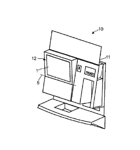
Figures 3a and 3b show a view of a device according to the invention for
handling
money transactions, 10, such as a pay machine or the like, with a housing, 11,
and a screen,
12, which screen, 12, is shown in a folded-in state in Figures 3a and 3b,
where Figure 3a
presents a frontal view and Figure 3b an oblique view. Screen 12 is oriented
vertically here
and the screen's surface, 1, is essentially flush with the front side of the
device's housing.
Figures 4a and 4b show a view of a device according to the invention for
handling
4
CA 02767299 2012-01-05
money transactions, 10, such as a pay machine or the like, with a housing, 11,
and a screen,
12, which screen, 12, is shown in a swung-out state in Figures 4a and 4b.
Screen 12 is
positioned here about a lower horizontal rotational axis from the vertical to
a somewhat
oblique, forward-leaning position.
Figure 5 shows schematically a screen, 100, with a screen surface, 1, on which
data,
text, or image information can be presented. Screen surface 1 is preferably
enclosed in a
mounting frame, 2. Screen 100 preferably exhibits at least one mount,
preferably on its back
side, or several mounts that are configured in such a way that the screen is
twistable about a
horizontal axis. In this connection, the axis can be arranged in the middle of
screen 100. See
reference sign 20. In another embodiment, the axis can be arranged in the
upper area of screen
100. See reference sign 21. In a further embodiment, the axis can be arranged
in the lower area
of screen 100. See reference sign 22. Furthermore, at least one mount is
configured so that the
screen is also twistable about a vertical axis. In this connection, the axis
can be arranged in the
middle of screen 100. See reference sign 23. In another embodiment, the axis
can be arranged
in the left area of screen 100. See reference sign 24. In a further
embodiment, the axis can be
arranged in the right area of screen 100. See reference sign 25.
Figure 6 shows schematically a screen, 100, with a screen surface, 1, on which
data,
text, or image information can be presented. Screen surface 1 is preferably
enclosed in a
mounting frame, 2. Screen 100 preferably exhibits at least one mount,
preferably on its back
side, configured in such a way that the screen is twistable about a horizontal
axis, 26, and a
vertical axis, 27. The mount is constructed advantageous here as ball joint
28, which is
advantageously arranged in the middle of the screen. However, ball joint 28
can also be
located elsewhere, such as for example on the screen's bottom or top area.
A monitor screen such as an LCD monitor or other monitor is advantageous for
displaying data, such as for instance image and/or text data.
The manual adjustment or rotation of the screen is advantageous, but
electromotive
adjustment can also be provided. Adjustment can occur both manually and
electromotively in
a preferred embodiment.
As described above, the screen is the screen of a device for handling money
transactions, where this device exhibits a housing and a screen enclosed in
the housing. The
5
CA 02767299 2012-01-05
screen, 100, is arranged here to be rotatable or tiltable about at least one
axis such that tilting
the screen can be effected manually or automatically.
Device according to the preceding claims, wherein electromotive operation of
the
screen is menu driven. A menu can be presented on the screen for this purpose
so that what
should subsequently be carried out can be selected from the menu. So, for
instance, the
adjustment can be controlled via the screen with a touch-sensitive screen such
as a touch
screen.
The degree of reflection from solar radiation or other light sources makes it
difficult to
read information on a screen, and is largely determined by the light source's
angle with the
screen or monitor, 100, and the angles A, B of the viewer's eyes to the
monitor, 100. Cf. Fig.
7.
The sun, 80, or light source, 81, moves along a path in front of the monitor,
100 (cf.
Figs. 8 and 9). The monitor, 100, is in a fixed position. The monitor, 100, or
the device in
which it is housed, is equipped with light sensors 101, 102, 103, and 104,
and/or a camera,
110 (cf. Fig. 9). In this case, the camera, 100, is a photographic apparatus
that can record still
or moving images on an electronic or digital storage medium.
The light sensors can involve sensors that change their electrical properties
during
interaction with light. Here this can be for example a photoresistor,
photodiode,
phototransistor, photocell, photomultiplier, or pyroelectric sensor.
The figure shows schematically the components of the device, 10, whereby a
central
control unit, 111, is connected to a sensor module, 112, and a camera module,
113, a monitor,
100, and a motor controller, 114, for adjusting the monitor, 100. The motor
controller, 114,
controls a drive unit, 116, coupled to the monitor, 100. The central control
unit, 111, further
includes calibration resource 117, monitor-angle-detection resource 118,
viewing-angle
resource 119, and reflection-angle-determination resource 120, and is
connected to electronic-
memory resource 115.
First, calibration is conducted using calibration resource 117. Fig. 12 shows
a
calibration workflow:
In this case, sensor module 112 includes light sensors 101, 102, 103, and 104.
According to
processing step 121, the intensity of solar radiation is measured with these
during the course
6
CA 02767299 2012-01-05
of one day, for instance. Maximum or absolute values are not necessarily
indicated here, but
the relative difference at various time points. The light sensors' measured
values can be
filtered for 'outliers' using various factors (such as buildings' influencing
solarization by
reflections during the day) according to processing step 122, as shown in Fig.
12. An
accumulation of differential values per time unit (e.g. minutes) is made
according to
processing step 123, The sun's position and the angle of incidence on the
screen or the screen
surface is explored with the aid of reflection-angle-detection resource 120 as
a function of the
day and season. The result yielded is the angular position of the sun in
relation to the monitor
throughout the day. This angle can be electronically stored in storage
resource 115 per unit
time for later comparison. If necessary, a new calibration will be performed
during the course
of the year (the sun is different in winter than in summer). Furthermore, in
principle,
calibration can be run continuously and used again as a reference at certain
times.
Fig. 13 describes the progression of changes to the screen's tilt with the aid
of monitor-
angle-detection resource 118:
According to processing step 131, the current time of day determined, for
example,
using a hardware-based or software-based real-time clock, as well as the
stored solarization
angle from storage means 115 are called up, or interpolation is done if
necessary, to determine
a solarization angle corresponding to a non-stored time-angle value.
The optimal view on the monitor is not only dependent on the solarization
angle, but
also on the position of the observer's eye relative to the monitor (cf. Fig.
7). According to
processing step 132, viewing-angle-determination means 119 detects the eyes
(position) of a
viewer located in front of monitor 100 with the help of images from camera 113
and a face-
detection algorithm. It then calculates the viewing angle A, B. According to
processing step
133, optimum angles for the monitor-orientation's horizontal and vertical axes
are calculated
based on the determined viewing angle and the called-up solarization angle.
Monitor-angle-
adjustment information so obtained is output to the motor controller.
According to processing
step 134, drive unit 116 then changes the tilt setting of monitor 100 with the
aid of motor
controller 114.
7