Note: Descriptions are shown in the official language in which they were submitted.
CA 02767484 2012-02-10
ADJUSTABLE MEASURING DISPENSER AND METHOD
This invention relates to measuring dispensers, and particularly to adjustable
measuring
dispensers for granular materials.
Certain types of dispensers are now sold and used primarily for dispensing
measured
quantities of granular materials such as sugar, etc. for sweetening coffee,
tea, cereal, etc. Those
dispensers are in need of improvement.
Such prior dispensers usually are relatively tall, and have a "pistol-grip"
type of lever
which, when pushed by the user, causes a pre-measured quantity of granular
material to be
dispensed through an opening in the bottom. Thus, the user can hold the
dispenser over a cup of
coffee or tea, or a bowl of cereal, etc., and dispenses sugar or other
sweetener by one or more
actuations of the lever.
A problem with such dispensers is that it is relatively difficult to change
the measured
quantity of material dispensed with each stroke of the lever. Typically, this
is done by providing
removable measurement inserts, in which one insert is removed from the device
and another is
inserted in its place in order to change the quantity being dispensed with
each stroke. For
example, if the dispenser is set up to dispense a half teaspoon with each
stroke, and it is desired
to change the measurement to one teaspoon, a '/2 teaspoon measurement element
is removed
from the dispenser and replaced with a one-teaspoon element to change the
amount dispensed to
a full teaspoon for each stroke.
This scheme of adjustment is cumbersome and difficult, especially in that it
requires the
user to store spare elements in a drawer or other such place. The spare
elements tend to get
misplaced, and it can require some time to hunt for them. Moreover, even if
the spare elements
are not lost, it is an undesirably slow process to exchange elements.
1
CA 02767484 2012-02-10
Other prior adjustable measuring dispensers have been provided with dial-type
adjustment means, so that a new quantity to be dispensed can be set by merely
turning a dial.
However, such prior dispensers suffer from other drawbacks, in that sometimes
they are not easy
to fill because the mechanism for adjustment is located at the top of the
device. Also, some such
devices do not dispense the material in a concentrated stream, but instead
spread the material
over a relatively wide area so that it sometimes is difficult to aim the
dispensed quantity into a
coffee or tea cup accurately.
Accordingly, it is an object of the invention to provide an adjustable
measuring dispenser
and method which alleviate or overcome the foregoing problems.
In particular, it is an object to provide a dispenser whose measurements can
be adjusted
quickly and easily, without having to replace parts of the dispenser.
It is a further object to provide such a dispenser in which extra parts need
not be stored
separately from the dispenser and are not therefore subject to loss.
Furthermore, it is an object of the invention to provide such a dispenser
which operates
freely and easily by the use of normal hand pressure by the user.
It also is an object to provide such a dispenser which is relatively
economical to build and
which provides measurements frequently needed for sugar and other sweeteners,
and other
granular and powdered condiments.
In accordance with the present invention, the foregoing objects are met by the
provision
of a measuring dispenser which uses a collapsible measuring dispensing chamber
to hold a
variable amount of material to be dispensed by means of a hand-operated lever,
and adjustment
means for adjusting the volume of the chamber by collapsing or expanding the
chamber to adjust
its volume.
2
CA 02767484 2012-02-10
Preferably, the collapsible chamber comprises at least two telescoping tubes
which are
slidable relative to one another. The adjusting mechanism allows the user to
easily adjust the
positions of the tubes relative to one another to change the quantity of
material dispensed.
No separate, easily-lost measuring elements need be handled or stored. Thus,
the
adjustment of the measuring device is relatively quick, easy, and reliable.
The foregoing and other objects of the advantages of the invention will be set
forth in or
apparent from the following description and drawings,
3
CA 02767484 2012-02-10
IN THE DRAWINGS:
Figure 1 is a side elevation view, partially broken-away, of an adjustable
measuring
dispenser constructed in accordance with the present invention;
Figure 2 is a front perspective view of the dispenser shown in Figure 1;
Figure 3 is cross-sectional view, partially broken-away, taken along line 3-3
of Figure 2,
and
Figure 4 is an exploded perspective view of the device shown in Figures 1-3.
GENERAL DESCRIPTION
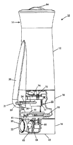
The adjustable measuring dispenser 10 shown in Figures 1 and 2 includes a
housing
formed of an upper section 12, a lower section 16, and a middle section 18,
all attached together.
A screw-on cap 14 is provided. A dispensing lever 20 extends outside of the
housing to be hand-
operated to actuate the dispensing mechanism.
Referring now to Figure 3, the upper housing section 12 forms a storage
chamber 26 for
storing granular or powdered materials 28 such as sugar, artificial sweetener,
salt, etc.
The storage chamber 26 can be refilled simply by removing the cap 14, pouring
the
material into the chamber through the open top of the dispenser, and replacing
the cap.
In accordance with one feature of the invention, the quantity of material to
be dispensed
with each stroke of the lever 20 is varied simply by rotating a dial 22 which
is accessible from
the front of the dispenser.
A window 24 with horizontal markings 25 (Figure 2) is provided for the purpose
of
indicating the setting of the dial 22, as it will be explained in greater
detail below.
4
CA 02767484 2012-02-10
Referring to Figures 1 and 3, an outlet storage chamber structure 30 is
provided directly
beneath the outlet opening 41 of the storage chamber 26. The lower bottom wall
42 of the
chamber 26 is sloped to guide the granular material 28 towards the outlet
opening 41.
The dispenser 10 has a bottom wall 43. A dispensing outlet opening 46 is
provided in the
bottom wall. The opening 46 is offset laterally from the position of the
outlet 41 of the storage
chamber 26, and the outlet storage chamber structure 30 is mounted to move
laterally towards
and away from the outlet 46 in response to depressing the lever 20.
The outlet chamber 30 comes to a rest position (in which it is shown in Figure
3) in
which it is aligned with the opening 41 from the storage chamber 26 to be
filled with granular
material under the force of gravity. When the outlet chamber 30 is moved to
the right into
alignment with the outlet opening 46, the contents of the outlet chamber 30
are dispensed
through the opening 46.
The outlet chamber 30 does not dispense more than its contents because its
inlet opening
moves to the right out of alignment with the opening 41 and cannot receive any
additional
material until it returns to its starting position beneath the opening 41.
OUTLET CHAMBER
The outlet chamber 30 includes a pair of telescoping tubes 32 and 34. The tube
34 has an
outside diameter D2 which is smaller than the internal diameter D1 of the tube
32. The tube 34
has a frustro-conical inlet opening 36 with an outer edge which makes close
contact with the
inner surface of the tube 32 to prevent or minimize the leakage of material
through the junction
point of the two tubes. Thus, the tube 34 can slide within the tube 32 with
little or no leakage
between the parts.
CA 02767484 2012-02-10
The outlet chamber 30 also includes a further tubular passageway 40 in a
carriage
structure 38. The passageway 40 has a slightly frustro-conical outlet portion
which ensures that
the contents of the outlet chamber will be accurately deposited through a tube
44 extending down
from a plate 48 and through a tube 41 and the outlet 46 to be dispensed. The
material is
dispensed in a concentrated stream of material so that it 'M11 be easy to
direct it into a coffee cup,
or teacup, or an even smaller receptacle, or onto any object to be covered
with the material.
The outside of the tube 44 and the inside of the tube 41 are slightly tapered
to ensure that
the tube 44 and the plate 48 can move upwardly and downwardly freely.
As it is shown in Figures 1, 3 and 4, the carriage 38 travels on a pair of
rails 50 and 52
which are mounted on the platform 48. The carriage 38 has downwardly extending
L-shaped
guides to guide it along the rails 50 and 52 with low friction, and to hold
the carriage 38 onto the
rails. The rails and guides preferably are molded from POM material, which is
strong and has a
low coefficient of friction.
The outlet chamber structure has a front extension member 54 with a rounded
leading
edge 59 which fits into a cavity 58 in the handle structure 20.
The outlet chamber structure also has an extending plate 56 at its upper edge.
The projection 54 provides a means for communicating the pushing force on the
lever 20
to the outlet chamber to move it from left to right, as shown in Figure 3. The
plate 56 is
dimensioned to cover the outlet opening 41 of the storage chamber 26 when the
outlet chamber
30 is moved towards the outlet 46 to prevent material from escaping unwantedly
from the
chamber 26.
When the outlet chamber 30 is returned to its rest position, the outlet
opening 41 once
again is in communication with the outlet chamber 30 to refill it.
6
CA 02767484 2012-02-10
A coil compression spring 72 is mounted between the right side wall of the
housing
section 18 and the side wall of the tube 32 to return the outlet chamber
structure 30 and the lever
20 to its initial starting position. The lever 20 has a hooked end 61 which
mates with a stop
member 63 on the edge of the housing to stop the lever when it has returned to
its starting
position.
MEASUREMENT ADJUSTMENT MECHANISM
The platform 48 (Figures 3 and 4) has a downwardly protruding tube 44
extending into a
receptacle 41 defining the outlet opening 46. As shown in Figure 4, the
receptacle 41, the tube
44, and the outlet opening 46 are oval in cross-section.
Extending downwardly from the bottom of the platform 48 is a vertical tubular
post 60
which has external helical threads, as shown primarily in Figure 1, but also
in Figure 4.
Surrounding the post 60 is a cylindrical internally-threaded member 62 whose
threads match
those on the post 60 and are shown engaged with those threads in Figure 3.
The outside surface of the sleeve 62 has a bevel gear 61 (see Figure 4 and
Figure 1). The
dial 22 has a drive shaft 66 fitted into a hub 69 and a bevel gear 64 designed
to mesh with the
bevel gear 61. A lock washer 67 (Figure 4) secures the two members 66 and 69
together. A
support structure 65 (Figures 1 and 3) is provided in which the structure 66-
69 rotates. The dial
22 has a flat central blade 23 which is easy to grasp when turning the knob.
Referring to Figure 4, reference number 49 indicates part of a detent
mechanism which
mates with a structure (not shown) on the inside of the dial 22 to provide
detent positions to
define three or more different settings for the volume to be dispensed with
each lever stroke. For
example, the three settings could be 1/2 teaspoon, 3/4 teaspoon, and 1
teaspoon.
7
CA 02767484 2012-02-10
When the knob 22 is rotated, the meshed spur gears rotate, thus turning the
element 62,
which then moves upwardly or downwardly to lift the platform 48 upwardly or
drop it
downwardly. This moves the rails 50, 52, and the carriage 38, as well as the
smaller tube 34
towards or away from the outlet opening 41 to vary the effective volume of the
outlet chamber.
HOUSING STRUCTURE
As it is shown in Figure 4, a mounting block 68 and a screw 70 are provided
for securely
rotatably mounting the threaded member 62 in the housing.
Referring now to Figure 4, the lower housing section 16 has two upstanding
mounting
posts 45 to which the parts above are mounted with screws (not shown).
Four hollow tubes 39 are provided to receive four downwardly-extending legs 37
which
slide in the tubes to guide the vertical movements of the platform 48 and its
attached
mechanisms.
The structure 74 with the mounting screws 75 shown in Figures 1 and 4 mount
and guide
the motion of the outlet chamber structure 30 and the upper plate 56.
The tube 34 is secured to the carriage 38 in fixed alignment with the hole 53
in the
carriage and the outlet member 40.
As shown in Figure 4, the lever 20 fits into recesses 78 and 86 in the housing
sections 12
and 18. A projection 76 at the top of the lever 20 fits into a cavity in the
housing in which it
pivots as the lower portion 21 of the lever 20 moves into and out of the
housing.
The cap 14 includes a lower frustro-conical cylinder 81, a top wall 82 with
shaker holes
83 and a selector cap 84 rotatable to uncover or cover the holes 83. Locking
notches 80 in the
upper edge of the housing section mate with locking tabs (not shown) in the
lower edge of the
8
CA 02767484 2012-02-10
cylinder 81 to provide a rapid-acting attachment mechanism to facilitate
removal and
replacement of the cap to refill the storage chamber 26.
The major parts of the dispenser are molded from plastic materials. The two
housing
sections 12 and 18 are heat-welded together, and the sections 16 and 18 are
held together by
screws threaded into the bosses 45.
METHOD OF USE
In use, the dispenser is used by simply holding it over a cup, bowl or other
receptacle or
object to be acted on by the material dispensed, and pressing on the lever 20
and releasing it once
or as many times as necessary to dispense the quantity desired.
If the user determines that too many strokes are required to dispense the
desired quantity,
the user merely turns the dial 22 to increase the quantity per stroke.
The window 24 allows the user to see the position of the platform 48, and the
corresponding quantity dispensed per stroke. Preferably, the quantity is
marked on the window.
If a quantity smaller than the current setting is desired, the dial 22 is
turned to a lower
setting.
The ability to choose a setting is beneficial to users in general, but is
particularly
beneficial to people whose hands shake and might dispense too much material
from shakers or
other dispensers.
The dispenser of the invention also is beneficial to those who need to
restrict their intake
of the materials and are aided by reliable measurements.
The dispenser can be used to dispense sugar and powdered artificial sweeteners
to great
advantage. Accurate measurement of sugar assures good tasting beverages or
cereal etc. and use
9
CA 02767484 2012-02-10
of the dispenser with artificial sweeteners avoids the need to handle and tear
open the usual
sweetener packets.
As it can be seen from the foregoing, the objective stated above for the
invention have
been met admirably by the structure and method described. The adjustment of
the quantity of
material dispensed can be made easily and quickly, simply by turning a dial on
the device. No
separate replacement parts need be stored, and the time taken to replace one
with another is not
needed. Therefore, the adjustment is easily and quickly made.
The device is easy to refill, simply by removing the top, filling it, and
replacing the top.
Moreover, the material is dispensed in a confined stream so as to make it
easier to aim the
contents into a tea cup, coffee cup, or similar receptacle.
The above description of the invention is intended to be illustrative and not
limiting.
Various changes or modifications in the embodiments described may occur to
those skilled in the
art. These can be made without departing from the spirit or scope of the
invention.