Note: Descriptions are shown in the official language in which they were submitted.
CA 02767528 2014-05-01
BUILDING STRUCTURE
TECHNICAL FIELD
This disclosure relates generally to building construction and, more
specifically, to a building structure and a method for forming thereof.
BACKGROUND
Hollow core slabs or voided slabs are prefabricated slabs of prestressed
concrete that are typically used in the construction of floors In multi-story
buildings. Hollow core slabs typically have tubular voids extending the length
of
the slab. Generally, the structure of the slab that is located between the
voids
includes steel rods that provide the majority of the tensile stress that holds
the
slab together. However, in certain applications, this structure does not
provide
the necessary shear capacity at bearing ends. In addition, in certain
applications, the tubular voids are partially filled with a pourable bonding
material. it can be difficult to control the amount of pourable bonding
material
that flows into the tubular voids and the slabs may still not provide the
necessary
shear capacity.
SUMMARY
The various embodiments of the present disclosure provide a building
structure having a poured bonding structure that Integrally connects columns,
beams, and flooring sections. The building structure includes elements that
are
quickly erected and then integrally connected with a poured bonding structure.
The flooring sections include voids and the voids can be filled with pourable
bonding material to facilitate integrating the flooring section with the other
- 1 -
CA 02767528 2015-02-24
elements of the building structure. Inserts are positioned in the voids to
limit the
amount of material that is permitted to enter the voids. The inserts include a
structure
that facilitates positioning the inserts in the voids such that the amount of
material
permitted to enter the voids can be optimized. The inserts also include a
structure
that reinforces the strength of the pourable bonding material that is in and
around the
void.
According to an exemplary embodiment, a framing structure includes a beam
and a flooring section that is supported by the beam. The beam and a supported
end
of the flooring section define a cavity, he flooring section includes voids
that open to
the cavity. A structural plate is positioned at a distance from the open end
of the void
and is configured to be adjustable along the length of the void. A bar extends
from
the plate toward and into the cavity.
In a broad aspect, the invention pertains to a building structure comprising a
beam that at least partially defines a cavity, a flooring section comprising a
void, the
beam supporting an end of the flooring section such that the void opens to the
cavity,
and an insert configured to be at least partially received within the void.
The insert
comprises a first structure configured to at least partially obstruct a flow
of pourable
material through the void, and a second structure configured to reinforce a
poured
bonding structure that is formed in the void.
The foregoing has broadly outlined some of the aspects and features of the
present disclosure, which should be construed to be merely illustrative of
various
potential applications. Other beneficial results can be obtained by applying
the
disclosed information in a different manner or by combining various aspects of
the
disclosed embodiments. Accordingly, other aspects and a more comprehensive
understanding may be obtained by referring to the detailed description of the
exemplary embodiments taken in conjunction with the accompanying drawings, in
addition to the scope defined by the claims.
- 2 -
CA 02767528 2015-02-24
BRIEF DESCRIPTION OF THE DRAWINGS
FIG. 1 is a partial perspective view of a building structure according to a
first
exemplary embodiment.
FIG. 2 is an exploded partial perspective view of a flooring section of the
buiiding structure of FIG. 1.
FIG. 3 is a cross sectional side elevation view of the building structure of
FIG. 1.
FIGs. 4 and 5 are cross sectional side elevation views of a building structure
according to alternative exemplary embodiments.
- 2a -
CA 02767528 2012-01-06
WO 2011/005970
PCT/US2010/041381
FIGs. 6 and 7 are views of an insert according to a second exemplary
embodiment.
FIGs. 8 and 9 are views of an insert according to a third exemplary
embodiment.
FIGs. 10 and 11 are building structures according to alternative
exemplary embodiments.
FIG. 12 is a perspective view of an insert according to a fourth exemplary
embodiment.
DETAILED DESCRIPTION
As required, detailed embodiments are disclosed herein. It must be
understood that the disclosed embodiments are merely exemplary and that the
present disclosure may be embodied in various and alternative forms, and
combinations thereof. As used herein, the word "exemplary" is used expansively
to refer to embodiments that serve as illustrations, specimens, models, or
patterns. The figures are not necessarily to scale and some features may be
exaggerated or minimized to show details of particular components. In other
instances, well-known components, systems, materials, or methods have not
been described in detail in order to avoid obscuring the present disclosure.
Therefore, specific structural and functional details disclosed herein are not
to be
interpreted as limiting, but merely as a basis for the claims and as a
representative basis for teaching one skilled in the art.
In general, the exemplary building structures described herein include
voided flooring sections and inserts that are configured to be positioned in
the
voids to control the flow of a pourable bonding material through the voids.
Each
of the inserts includes a first structure that at least partially closes the
path of or
partitions the void. Each of the inserts can also include a second structure
for
use as a handle to facilitate positioning the first structure and/or for use
as a
reinforcing structure to strengthen a poured bonding structure that is formed
around the handle.
A first structure of the insert can include a stop, a plug, a plate, a series
of
- 3 -
CA 02767528 2012-01-06
WO 2011/005970
PCT/US2010/041381
plates, a wire-frame mesh structure, an inflatable structure, a ball, a
malleable
structure, a moldable structure, a rigid structure, combinations thereof, and
the
like. The material used to form the first structure can include metal,
plastic,
composites, cloth, wire, mesh, combinations thereof, and the like.
A second structure of the insert can include a handle bar, a rod, an
anchor, a deformed bar, a formed section of bar, a mesh extension,
combinations thereof, and the like. The material used to form the second
structure can include metal, plastic, composites, combinations thereof and the
like.
The selection of structure and material can be determined, for example,
based on the needs and budget of a user. High strength materials can be
selected where the user desires that the insert reinforces a poured bonding
structure in and around the void. Low cost materials can be used where the
user
wants to limit the depth that pourable bonding material can flow into the void
and
reinforcing the poured bonding structure is less important.
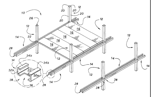
Referring to FIG. 1, a first exemplary embodiment of a building structure
10 includes a plurality of columns 12, a plurality of beams 14, a plurality of
flooring sections 16, and a poured bonding structure 18 (shown in FIG. 3). The
exemplary columns 12, beams 14, and flooring sections 16 can be formed from
material or materials that have characteristics which meet minimum performance
requirements including steel, aluminum, wood, pre-cast concrete, composite
materials, combinations thereof, and the like.
The illustrated columns 12 and beams 14 have steel walls that are
configured to receive pourable bonding material to form composite structures.
The illustrated columns 12 and beams 14 are used to form the sheath of
composite columns and beams that include a core formed from a pourable
bonding material.
The illustrated flooring sections 16 are hollow-core or voided slabs or
planks that are prefabricated and made of prestressed concrete. It is
contemplated that, in alternative embodiments, the flooring sections can
include
metal deck sections, wood planks, pre-cast concrete planks, poured-in-place
- 4 -
CA 02767528 2012-01-06
WO 2011/005970
PCT/US2010/041381
structures, double T planks, single T planks, post-tensioned pre-cast
sections,
pan-formed sub flooring, composite structures, combinations thereof, and the
like.
The illustrated poured bonding structure 18 (FIG. 3) is a pourable bonding
material 18 that has solidified. As used herein, the term "bonding" is used to
include materials that can form structures that link, connect, form a union
between, or attach multiple structures to form a composite structure. As used
herein, the term "pourable" in reference to bonding material is used to
include
bonding material that is in a moldable or substantially fluid state such that
the
material conforms to the shape of the container in which it is poured. The
term
"poured bonding structure" is used to include bonding material in a
substantially
rigid state or pourable bonding material that has solidified into a
substantially
rigid structure. These terms are used for purposes of teaching and in a non-
limiting manner. Such bonding materials can include concrete, plasticized
materials, cementitious materials, cement, grout, GypereteCI, combinations
thereof, and the like.
Continuing with FIG. 1, the beams 14 extend in a longitudinal direction
and the ends thereof are supported by columns 12 at a height that corresponds
to a floor or level of the building structure 10. Flooring sections 16 extend
in a
transverse direction and the ends thereof are supported by beams 14. The
flooring sections 16 define a base layer of a floor of the building structure
10. As
will be described in further detail below, the poured bonding structure 18
integrates the columns 12, the beams 14, and the flooring sections 16 such
that
the building structure 10 is substantially unitary.
Elements of the building structure 10 are described in further detail. The
illustrated building structure 10 is formed from pluralities of like-numbered
elements that are substantially similar. Although only a representative one or
representative ones of the like-numbered elements may be described in detail,
this description is generally applicable to each of the other like-numbered
elements. Numbers alone are used to generally reference one of like-numbered
elements or a group of like-numbered elements and suffixes such as "a" or "b"
- 5 -
CA 02767528 2012-01-06
WO 2011/005970
PCT/US2010/041381
are attached to the numbers in order to reference individual ones of the like-
numbered elements.
Referring to FIG. 1, the illustrated column 12 is a hollow-interior, box-style
beam having a substantially square cross-section defined by four walls 20. The
column 12 includes openings 22 that are disposed in certain of the walls 20 so
as to provide a passageway between the exterior and the interior 26 of the
column 12. The size, shape, and number of openings 22 are determined so as
to allow a pourable bonding material 18 to flow through the openings 22
without
substantially adversely affecting the structural integrity of the column 12.
The illustrated openings 22 are disposed in the column 12 at positions
that generally correspond to where the ends of beams 14 substantially meet the
column 12. In other words, the openings 22 are positioned to generally
correspond to the floors or levels of the building structure 10. The columns
12
and the beams 14 are positioned with respect to one another such that the
openings 22 of the columns 12 substantially align with cavities 28 of the
beams
14.
Referring to FIGs. 2 and 3, the beam 14 has a trough-like or channel-like
structure in that the upward facing cavity 28 functions to receive and retain
pourable materials. The exemplary beam 14 has a squared, U-shaped cross-
section, although in alternative embodiments the cross-section of the beam 14
can be V-shaped, rounded U-shaped, H-shaped, and any other shape that
provides the functionality described herein.
The beam 14 includes a base wall 30 and side walls 32a, 32b that extend
vertically upward from the base wall 30 so as to define the cavity 28.
Cantilevers
34a, 34b extend inwardly from the upper ends of the side walls 32a, 32b to
provide a surface for supporting flooring sections 16, as described in further
detail below. Alternatively, the cantilevers 34a, 34b can be arranged to
extend
outwardly from the sidewalls 32, one cantilever can extend inwardly and the
other outwardly, or cantilevers can extend both inwardly and outwardly.
Referring to FIG. 1, a cutout 36 is defined in the base wall 30 at each of
the ends 38 of the beam 14. The cutout 36 is dimensioned with respect to the
- 6 -
CA 02767528 2012-01-06
WO 2011/005970
PCT/US2010/041381
column 12 such that the column 12 can be received in the cutout 36.
Accordingly, in the illustrated embodiment, the cutout 36 is squared to
correspond to the squared cross-section of the column 12. The depth of the
illustrated cutout 36 is substantially equal to half of the depth of the
column 12
and the width of the illustrated cutout 36 is substantially equal to the width
of the
column 12. Thus, when the column 12 is received in the cutouts 36 of abutting
beams 14, the ends 38 of the beams 14 substantially abut one another to, in
effect, provide a continuous beam 14.
Referring again to FIGs. 2 and 3, the illustrated flooring sections 16 are
pre-cast concrete planks that include internal tubular voids 60. The tubular
voids
60 facilitate integration of the flooring sections 16 with the other elements
of the
building structure 10, as described in further detail below. Each illustrated
flooring section 16 is arranged such that open ends of the tubular voids 60
are
located in the end of the flooring section 16 that is supported by the beam
14.
The supported end of the flooring section 16 also partially defines the cavity
28,
and the tubular voids 60 open to the cavity 28 such that the cavity 28 and the
tubular voids 60 are a continuous volume. Flooring sections 16 increase the
depth of the cavity 28.
The illustrated tubular voids 60 are configured to receive inserts 62. In
alternative embodiments, the flooring sections 16 can include other features
for
receiving inserts including partial voids, depressions, recesses, and the
like.
In the illustrated embodiment, inserts 62 are configured to be received in
the tubular voids 60. The illustrated insert 62 includes a structural plate 64
and a
reinforcing rod 66 that are connected to one another. The illustrated
structural
plate 64 includes an aperture 70 and the reinforcing rod 66 is threaded. The
reinforcing rod 66 is inserted through the aperture 70 and threaded through
bolts
72 on opposed sides of the structural plate 64. The bolts 72 are configured to
tighten against the structural plate 64 to rigidly connect the reinforcing rod
66
and the structural plate 64. Alternatively, the structural plate 64 and the
reinforcing rod 66 can be welded to one another, adhered to one another,
pinned
to one another, chemically affixed to one another, mechanically connected to
one another, combinations thereof, and the like.
- 7 -
CA 02767528 2012-01-06
WO 2011/005970
PCT/US2010/041381
The structural plate 64 can be positioned within the tubular void 60 at
different distances 68 from the open end of the tubular void 60 to adjust the
depth which pourable bonding material 18 is permitted to flow into the tubular
void 60. The shape and dimensions of the illustrated structural plate 64 is
substantially that of the cross section of the tubular void 60 such that the
structural plate 64 substantially partitions or closes the tubular void 60.
The
shape of each of the illustrated structural plates 64 and the cross section of
each
of the illustrated tubular voids 60 is circular. Alternative shapes include
ovals,
squares, rectangles, combinations thereof, and the like. The thickness 74 of
the
illustrated structural plate 64 is selected such that the structural plate 64
does
not rotate in the tubular void 60, for example, as a force that creates a
moment is
applied to the reinforcing rod 66. The movement of the structural plate 64 is
substantially limited to translation in the tubular void 60. The thickness 74
may
be increased to account for a situation where the dimensions of the structural
plate 64 are not substantially tightly toleranced with respect to the tubular
void
60.
The illustrated reinforcing rod 66 is configured to facilitate positioning the
structural plate 64 in the tubular void 60, to increase the strength of the
poured
bonding structure 18 both in the tubular void 60 and in the cavity 28, and to
distribute forces on the poured bonding structure 18 in the tubular void 60 to
the
poured bonding structure 18 in the beam 14.
The illustrated reinforcing rod 66 has a first length 76 that extends from
the structural plate 64 through the tubular void 60 and into the cavity 28.
The
first length 76 is substantially centered in the tubular void 60 and is
substantially
perpendicular to the structural plate 64. The illustrated reinforcing rod 66
is
formed or shaped so as to also include a second length 78 that extends in the
cavity 28 and is substantially perpendicular to the first length 76. The shape
of
the illustrated reinforcing rod 66 can facilitate the use of the reinforcing
rod 66 as
a tool for positioning the structural plate 64 along the length of the tubular
void
60. The second length 78 can be easily engaged by a user to move the
structural plate 64 along the longitudinal axis of the tubular void 60. The
second
length 78 can also function to limit the distance 68 that the structural plate
64
- 8 -
CA 02767528 2012-01-06
WO 2011/005970
PCT/US2010/041381
can be positioned in the tubular void 60. For example, the second length 78
can
be configured to contact the outside surface of the end of the flooring
section 16
and obstruct further movement of the structural plate 64 into the tubular void
60.
A function of the reinforcing rod 66 is to reinforce or strengthen the poured
bonding structure 18. The structural plate 64 provides a base that supports
the
end of the reinforcing rod 66 to position the reinforcing rod 66 in the
tubular void
60 and in the cavity 28. Here, the fit between the structural plate 64 and the
tubular void 60 maintains the position of the reinforcing rod 66.
By way of example and not limitation, in alternative embodiments, means
for reinforcing can include round bar, rebar, flat bar, any dimensional stock,
deformed bar anchors, formed sections of rebar, rebar hooks, ribs, fins,
anchor
bolts, other anchoring elements, combinations thereof, and the like. Referring
momentarily to FIGs. 4, 5, and 12, an exemplary anchoring element 79 is
attached or integral to the reinforcing rod 66. Anchoring elements 79 prevent
slip of reinforcing rod 66, for example, where the length of reinforcing rod
66 is
relatively short.
A function of the illustrated insert 62 is to facilitate positioning lengths
of
rebar 80 in the cavity 28 of the beam 14 prior to the beam 14 receiving a
pourable bonding material 18, such as concrete. The inserts 62 each include a
structure that facilitates attaching the lengths of rebar 80 thereto. As
illustrated
in FIG. 2, the rebar 80 is attached to the second lengths 78 of the inserts
62.
The length of the second length 78 can be increased such that additional
lengths
of rebar 80 can be attached thereto. Further, lengths of rebar 80 can be
attached to the portion of the first length 76 that is positioned in the
cavity 28.
Referring to FIGs. 4 and 5, the reinforcing rods 66 can be configured such
that
lengths of rebar 80 can rest on the reinforcing rod 66. Means for attaching
the
lengths of rebar 80 to the inserts 62 can include welds, ties, bending,
adhesives,
combinations thereof, and the like.
An exemplary method of constructing the building structure 10 is now
described. It is contemplated that the building structure 10 can be erected
according to alternative methods, for example, by altering the order of the
steps
of the exemplary method or by adding steps to or omitting steps from the
- 9 -
CA 02767528 2012-01-06
WO 2011/005970
PCT/US2010/041381
exemplary method. Referring first to FIG. 1, a plurality of columns 12 are
erected and a plurality of beams 14 are positioned to extend longitudinally
between erected columns 12 such that the cavities 28 of the beams 14 align
with
the openings 22 of the columns 12. Specifically, the columns 12 are received
in
the cutouts 36. The ends 38 of adjacent aligned beams 14 abut one another and
the abutting ends 38 of the side walls 32a, 32b of the beams 14 can be
attached,
such as by bolting or welding, to one another. Thus, abutting beams 14 provide
a substantially continuous beam 14 having a base wall 30 that is interrupted
by a
column 12. It should be noted that the abutting beams 14 are substantially
continuous along the side walls 32a, 32b, the cantilevers 34a, 34b, and
portions
of the base walls 30 such that pourable bonding material 18 in the cavities 28
can flow around the exterior of the column 12.
Referring now to FIGs. 1-3, the illustrated flooring sections 16 are set on
erected beams 14 such that one end of each of the flooring sections 16 is
supported on the support surface provided by a cantilever 34a of one beam 14
and the opposite end of each of the flooring sections 16 is supported on the
support surface provided by a cantilever 34b of another beam 14, with the
tubular voids 60 opening to the cavities 28. Since abutting beams 14 provide
substantially continuous cantilevers 34a, 34b or are otherwise not interrupted
by
the columns 12, the flooring sections 16 can abut one another along side-by-
side
edges to provide a substantially continuous floor or level, even near the
columns
12. In alternative embodiments, only one end or section of a flooring section
16
is supported by a beam 14 while an opposite end is cantilevered over another
beam or supported by another shape of beam.
Inserts 62 are inserted into the tubular voids 60. For example, each insert
62 can be gripped by the second length 78 of the reinforcing rod 66 to guide
the
structural plate 64 into the tubular void 60. As previously mentioned, the
position
of the structural plate 64 in the tubular void 60 limits the depth that
pourable
bonding material 18 can flow into the tubular void 60.
Referring again to FIG. 2, lengths of rebar 80 or other reinforcing
members, such as post tensioned cables (not shown), extend within the cavity
28, and through the openings 22 in the column 12. The illustrated lengths of
-10-
CA 02767528 2012-01-06
WO 2011/005970
PCT/US2010/041381
rebar 80 are tied or otherwise attached to the inserts 62. Thereby, the
lengths of
rebar 80 are positioned within the cavities 28 according to a highly efficient
method.
Referring next to FIGs. 1 and 3, pourable bonding material 18 such as
concrete is poured to first fill the hollow interiors 26 of the columns 12.
The
pourable bonding material 18 can be directly poured into the hollow interior
26
through the opening 22 or, as the pourable bonding material 18 is poured into
the cavity 28, the pourable bonding material 18 is channeled through the
opening 22 to fill the hollow interior 26. Once the column 12 is filled up to
substantially the height of the base wall 30 of the beam 14, the cavity 28
then
continues to fill until the level of pourable bonding material 18 reaches the
height
to fill the beam 14. The cavity 28 continues to fill until the level of
pourable
bonding material 18 is substantially coplanar with the top surface of the
flooring
sections 16 so as to at least partially fill the tubular voids 60. Since the
tubular
voids 60 are closed with inserts 62, the tubular voids 60 are only filled to a
certain depth 68, which reduces the weight of the building structure 10. In
alternative embodiments, hollow core columns 12 are exchanged for other
column shapes, columns of other materials, and solid columns of other shapes
and material.
Pourable bonding material 18 is further poured to define a layer of floor
thickness that tops the flooring sections 16. This layer of floor thickness
increases the rigidity of the building structure 10. Once the pourable bonding
material 18 solidifies, the resulting poured bonding structure 18 integrally
connects the beams 14, the columns 12, and the flooring sections 16 to provide
the integrated building structure 10.
Turning now to FIGs. 6-9, alternative embodiments of inserts are
described. Referring to FIGs. 6 and 7, a second embodiment of an insert 162 is
illustrated. The insert 162 includes a deformable structure 164 and a handle
bar
166. The illustrated deformable structure 164 is configured to limit the flow
of
pourable bonding material into the tubular void 60 and includes a mesh body
168
with a wire frame 170. The mesh body 168 can be a material such as metal or
fabric so long as it is deformable and not so porous as to allow pourable
bonding
-11-
CA 02767528 2012-01-06
WO 2011/005970
PCT/US2010/041381
material to flow through it, The handle bar 166 can be connected, for example,
to a ring at the center of the mesh body 168.
The illustrated wire frame 170 has a diameter that is greater than the
diameter of the tubular void 60. Referring to FIG. 7, as the deformable
structure
164 is forced into the tubular void 60 with the handle bar 166, the wire frame
170
is partially collapsed and retained in a collapsed condition by the tubular
void 60.
The wire frame 170 presses against the inner wall of the tubular void 60 such
that the mesh body 168 substantially forms a partition. In the illustrated
embodiment, the handle bar 166 is used to position the deformable structure.
In
certain alternative embodiments where the deformable structure 164 does not
support and position the handle bar 166, the insert 162 can include a support
structure such as one or more wheels that positions the handle bar 166. In
other
alternative embodiments, the handle bar 166 is omitted.
Referring to FIGs. 8 and 9, a third embodiment of an insert 262 is
illustrated. The insert 262 includes a pair of wheels 264a, 264b and a
reinforcing
rod 266. The wheels 264a, 264b support and position the reinforcing rod 266 in
the tubular void 60. The distance 268 between the wheels 264a, 264b can be
adjusted to increase or decrease the support that is applied to the
reinforcing rod
266. Increasing the distance 268 can increase the support and decreasing the
distance reduces the profile of the wheels 264a, 264b along the longitudinal
dimension of the tubular void 60. The wheel 264a is illustrated as being
configured to obstruct the flow of pourable bonding material therethrough. In
alternative embodiments, the positions of the wheels 264a, 264b are switched,
which would increase the depth that pourable bonding material 18 is permitted
to
flow into the tubular void 60.
Referring to FIGs. 10 and 11, building structures 310, 410 that include
other types of flooring sections 316, 416 are illustrated. Referring to FIG.
10,
flooring section 316 is metal decking that includes troughs and raised
sections.
Insert 364 is positioned in a void 360 between a raised section of the
flooring
section 316 and the beam 14. The insert 364 can be secured in place. In one
embodiment, the insert 364 is secured in place by fillet welds 52.
Alternatively,
the insert 364 is press fit in the void 360. Reinforcing rod 366 is supported
by
- 12 -
CA 02767528 2012-01-06
WO 2011/005970
PCT/US2010/041381
the insert 364 and extends from the void 360 into the cavity 28 of the beam
14.
A pourable bonding structure (not shown) that fills the cavity 28 embeds the
portion of the reinforcing rod 66 that is in the cavity 28 to connect the beam
14 to
the flooring section 316. In various embodiments, the reinforcing rod 366 is
fillet
welded 52 to both the flooring section 316, and/or to the beam 14, and/or to
the
insert 364.
Referring to FIG. 11, flooring sections 416 are wooden beams. The
reinforcing rod 66 is inserted through an aperture 418 in the flooring section
416
to attach an end of the reinforcing rod 66 to the flooring section 416. The
reinforcing rod 66 extends into the cavity 28 of the beam 14 and connects the
flooring section 416 and the beam 14 as a poured bonding structure (not shown)
is formed in the cavity 28 and embeds an end of the reinforcing rod 66. In
various embodiments, various connections may be used to attach the reinforcing
rod 66 to the beam 14 or flooring sections 316, 416, including welding,
threaded
bolt connections, friction fit, hooked connectors, combinations thereof, and
the
like
The law does not require and it is economically prohibitive to illustrate and
teach every possible embodiment of the present claims. Hence, the above-
described embodiments are merely exemplary illustrations of implementations
set forth for a clear understanding of the principles of the disclosure.
Variations,
modifications, and combinations may be made to the above-described
embodiments without departing from the scope of the claims. All such
variations, modifications, and combinations are included herein by the scope
of
this disclosure and the following claims.
- 13 -