Note: Descriptions are shown in the official language in which they were submitted.
CA 02768030 2012-01-13
WO 2011/006247
PCT/CA2010/001098
METHOD AND APPARATUS FOR PICKING A PACKAGE FROM A DISPENSING
SYSTEM
FIELD OF THE INVENTION
This invention relates to storage apparatus including a pick head arrangement
for a package
dispensing system. It has particnlar application for picking and loading
medicament
products, such as drugs, at a medicament dispensary kiosk.
DESCRIPTION OF RELATED ART
Medicament packages to be dispensed at a robotically controlled dispensing
kiosk may be
pre-packaged pill boxes, bottles or the like having a range of sizes, shapes,
weight, weight
distribution and surface condition, all of which may create handling problems
for a robotic
system. Drug companies frequently change packaging, so control algorithms may
become
ineffective if a control algorithm is based on the product packaging. A
control algorithm
that prescribes a handling method based solely on pre-recorded product package
information (weight, size, etc) is prone to error. To reduce package handling
problems,
uniform style and shape of outer-packaging can be applied to medicament
products,
although this is not preferred as it adds additional handling and expense, may
introduce
other errors, and results in extra packaging materials. Ideally, the control
algorithms and the
package handling hardware utilized throughout a package picking process should
be as
flexible as possible commensurate with other demands of the dispensary kiosk.
In known medicament dispensary kiosks for dispensing bottles or packages of
drugs or other
medicament packages, the packages are typically stacked in a row column rack
of bins.
SUMMARY OF THE INVENTION
According to one aspect of the invention, there is provided a storage
apparatus comprising a
rack of storage bins, a pick head including a platform, a pick head drive unit
to drive the pick
1
CA 02768030 2014-07-16
head to an access location corresponding to a selected bin, and a platform
drive unit to drive
the platform into and out of the rack from the access location, the platform
having a cam
formation for lifting a package stored in the selected bin when the platform
reaches an
actuation position in the course of the platform entry, the platform having an
engagement
means to engage the selected package when the platform reaches a withdrawal
position in
the course of platform entry, the engagement means in the course of the
platform exit,
acting to drag the package out of the selected bin.
According to another aspect of the invention, there is provided a method for
picking a
package stored in a selected bin of a rack of storage bins, the method
comprising operating a
pick head drive unit to drive a pick head to an access location corresponding
to the selected
bin, operating a platform drive unit to drive the platform into and out of the
rack from the
access location, by means of a cam formation on the platform lifting a package
stored in the
selected bin when the platform reaches an actuation position in the course of
the platform
entry, by means of an engagement means on the platform engaging the selected
package
when the platform reaches a withdrawal position in the course of platform
entry, and by
means of the engagement between the engagement means and the package dragging
the
package out of the selected bin in the course of the platform exit from the
rack.
In accordance with a further aspect of the invention, a storage apparatus is
provided which
comprises a rack of storage bins and a pick head. The pick head includes a
platform having a
cam with a leading portion and an opposing trailing portion, and a pick head
drive unit to
drive the pick head to an access location corresponding to a selected storage
bin having a
floor for supporting a package having a leading portion and an opposing
trailing portion. The
pick head further includes a scissors-type telescopic drive unit to drive the
platform by
telescoping into the selected said storage bin in the rack from the access
location. The
leading portion of the cam progressively tilts the leading portion of the
package away from
and off of the floor in the selected storage bin as the leading portion of the
cam progressively
telescopes into the selected storage bin under the package. The trailing
portion of the cam
progressively tilts the trailing portion of the package towards and back on to
the floor in the
selected storage bin as the trailing portion of the cam progressively
telescopes under and past
the trailing portion of the package. The scissors-type telescopic drive unit
drives the platform
by telescoping out of the selected storage bin in the rack from the access
location such that
2
CA 02768030 2014-07-16
the trailing portion of the cam engages the trailing portion of the package to
drag the package
on the floor out of the selected storage bin.
In another aspect of the invention, a storage apparatus is provided which is
comprised of a
rack of storage bins and a pick head. The pick head includes a platform having
a cam with a
leading portion and an opposing trailing portion, and a telescopic pick head
drive unit. The
drive unit drives the pick head to an access location corresponding to a
selected storage bin
having a floor for supporting a package having a leading portion and an
opposing trailing
portion. The telescopic pick head drive unit has a spool of drive tape, and
the drive tape has a
free end fixed to the platform, ready bendability in a first direction to
permit storing at the
spool upon platform exit, and relative unbendability in an opposed direction.
The drive tape
provides axial thrust and platform entry upon unwinding of the spool, and the
drive tape
drives the platform by telescoping into and out of the rack from the access
location. The
leading portion of the cam progressively tilts the leading portion of the
package away from
and off of the floor in the selected storage bin as the leading portion of the
cam progressively
telescopes into the selected storage bin under the package. The trailing
portion of the cam
progressively tilts the trailing portion of the package towards and back on to
the floor in the
selected storage bin as the trailing portion of the cam progressively
telescopes under and past
the trailing portion of the package. The telescopic pick head drive unit
drives the platform by
telescoping out of the selected storage bin in the rack from the access
location such that the
trailing portion of the cam engages the trailing portion of the package to
drag the package on
the floor out of the selected storage bin.
BRIEF DESCRIPTION OF THE DRAWINGS
For simplicity and clarity of illustration, elements illustrated in the
following figures are not
drawn to common scale. For example, the dimensions of some of the elements are
exaggerated relative to other elements for clarity. Advantages, features and
characteristics of
the present invention, as well as methods, operation and functions of related
elements of
structure, and the combinations of parts and economies of manufacture, will
become apparent
upon consideration of the following description and claims with reference to
the
accompanying drawings, all of which form a part of the specification, wherein
like reference
numerals designate corresponding parts in the various figures, and wherein:
2a
CA 02768030 2012-01-13
WO 2011/006247
PCT/CA2010/001098
FIG. 1 is a front view of a storage apparatus for a package dispensing kiosk
according to one
embodiment of the invention;
FIG. 2 is a perspective view of a bin rack forming part of the storage
apparatus of FIG. 1;
FIG. 3 shows a detail from the front of a rack of bins forming part of the
storage apparatus
of FIG. 1;
FIG. 4 shows a top view of the detail of FIG. 3;
FIG. 5 is a perspective view of one embodiment of pick head for use in picking
items from a
storage bin;
FIG. 6 is scrap view of a part of the platform of FIG. 5;
FIG. 7 is a perspective view corresponding to FIG. 5, but showing a
reciprocable platform
thereof in an extended position;
FIG. 8 is a longitudinal sectional view through part of the pick head and
adjacent storage bin
according to an embodiment of the invention;
FIG. 9 is a top view corresponding to FIG. 8;
FIG. 10 is a longitudinal sectional view corresponding to the view of FIG. 8,
but showing a
platform forming part of the pick head in a rearward position;
FIG. 11 is a longitudinal sectional view corresponding to the view of FIG. 8,
but showing
the platform in a more rearward position;
FIG. 12 is a longitudinal sectional view corresponding to the view of FIG. 8,
but showing
the platform in a package drop position;
3
CA 02768030 2012-01-13
WO 2011/006247
PCT/CA2010/001098
FIG. 13 is a longitudinal sectional view corresponding to the view of FIG. 8
but showing the
pick head and picked package retrieved from a bin rack;
FIG. 14 is a perspective view of a pick head according to another embodiment
of the
invention, the arrangement shown with a platform forming part of the pick head
in an
unextended condition;
FIG. 15 is a perspective view corresponding to FIG. 14 but showing the
platform in an
extended condition;
FIG. 16 is a longitudinal sectional view corresponding to the views of FIGs.
14 and 15.
FIG. 17 is a perspective view of a pick head according to a further embodiment
of the
invention, the arrangement shown with a platform forming part of the pick head
in an
unextended condition;
FIG. 18 is a perspective view of a platform and spool arrongement forming a
part of the
FIG. 17 embodiment;
FIG. 19 is a side view of the platform and spool arrangement of FIG. 18;
FIG. 20 is a perspective view corresponding to FIG. 17 but showing the pick
head in an
extended condition;
FIG. 21 shows a demi' from the front of a tack of bins forming part of a
storage apparatus
according to an embodiment of the invention; and
FIG. 22 shows a top view of the detnil of FIG. 21.
4
CA 02768030 2012-01-13
WO 2011/006247
PCT/CA2010/001098
DETAILED DESCRIPTION OF THE INVENTION INCLUDING THE PRESENTLY
PREFERRED EMBODIMENTS
In a medico n-tent dispensary kiosk for dispensing bottles or packages of
drugs or other
medicament packages, the packages are typically stacked in a row column rack
of bins. To
pick a package from a bin, a pick head is driven in X and Y directions to a
desired XY
position corresponding to the selected bin. A platform forming part of the
pick head is then
moved in the Z direction to pick the package from the selected bin.
In a prior implementation of a pick head as described in out copendin
Canadian patent
application serial number 2,639,239, with a pick head at a desired XY position
and a
platform adjacent the target bin, the platform is moved to a position
underlying a slot
formed in a lower wall of the target bin. In the package pick action, after
the platform is
driven a sufficient distance rearwardly in the Z direction, the platform is
raised so that an
upwardly extending hook on the platform is brought to a position immediately
behind the
package to be picked. The package to be picked is then hooked out of the
selected bin by
driving the platform forwardly out of the rack of bins.
Once the picked package is on the platform, further investigation is made to
ensure the
package is really the one whose selection is desired. Typically, this might
include checking a
bar code affixed to the package and/or examining physical characteristics of
the package
such as its shape or weight. The platform, with the package supported upon it,
is then
moved to a rest position on the pick head whereupon the pick head is driven to
another part
of the apparatus as part of the dispensing procedure.
Within a medicament storage kiosk of the type described in the copending
Canadian patent
application 2,639,239, it is desirable to have the pick head and its operation
occupy a small
space so that as much rack space as possible can be used for the storage of
medicaments.
In the pick operation described previously, the raising of the platform once
it has been
driven under a bin means that a layer of space under each row of bins must be
reserved. In
addition, the 3-part platform movement - platform moves rearwardly, platform
moves
upwardly, platform moves forwardly ¨ is a relatively complex procedure.
CA 02768030 2012-01-13
WO 2011/006247
PCT/CA2010/001098
It would be valuable if at least a part of the layers of space under each row
of bins which are
reserved as the platform lifting space could be used for further storage. It
would be
valuable also if a simpler procedure could be implemented for picking packages
from the
bins.
Referring in detail to FIGs. 1 and 2, there is shown a cabinet 10 for a
dispensing kiosk, the
cabinet having a rack 11 of storage bins 12 arranged in a row and column
array. The bins
may be of a uniform shape and size or, as shown, may vary in shape and size to
accommodate different sizes of packages to be dispensed. Particularly for the
application
envisioned for the present invention, the rack of storage bins is formed as a
secure back end
medicament storage vault. The storage vault is in use combined with a front
end unit (not
shown) which bars unauthorized access to the drug vault but which can be
opened to expose
the drug vault for servicing. Mounted in the front end unit is an interface
unit (not shown)
at which a user, can enter data, communicate with a remote expertise or data
records
through a data or teleconference link, and collect dispensed packages, etc.
As shown in FIGs. 3 and 4, each bin has a pair of side walls 14 with the side
walls of inner
ones of the bins also being the side walls of immediately laterally adjacent
bins. Similarly,
each bin has an upper wall 15 and a lower wall or floor 16, with the upper and
lower walls of
the inner bins forming the lower and upper walls of immediately vertically
adjacent bins.
The rack of bins has a rear wall 17 extending the full extent of the array
although, as an
alternative, stub rear walls can be used for each row of bins in place of the
fully extending
rear wall. The bins have a front to back depth typically to accommodate a row
of four
packages. In a typical application, these are pill boxes or bottles, but may
also be bottles
containing dispensed liquid medicaments or may be different packages entirely.
An
embodiment of the invention relates to the manner of picking a package, which
may be a
single package within a bin or which may be the first package of a vertical
stack or of a
horizontal row of packages which have to be selectively manipulated to obtain
access to a
desired package.
A chosen package is picked from its position in the rack of bins and, if part
of a stack or row
of packages, from its position within the stack or row, in preparation for
dispensing the
6
CA 02768030 2012-01-13
WO 2011/006247
PCT/CA2010/001098
package at an access bay in the front end interface unit. Each of the bin
floors 16 has a slot
18 which is generally centered within the floor and which extends from the
front access side
19 of the bin to a position near the rear of the bin.
As shown in FIG. 1, a pick head 20 is mounted on a vertically reciprocable
carriage 21 which
is driven by a belt drive 22 along a vertical guide rail 23. The rail 23 is
mounted between two
horizontally reciprocable carriages 24. The carriages 24 are driven by belt
drives 26 along
horizontal rails 28. The carriages 21 and 24 move in a plane which extends
parallel to a front
access side 19 of the bin rack 11. In this way, the pick head 20 can be placed
adjacent any
selected one of the bins 12 at the front access side 19 of the bin rack.
In one embodiment of the invention, and as shown in perspective view in FIGs.
5 and 7, the
pick head 20 includes a platform 32 and a scissors type telescopic supporting
linkage 34
(FIG. 7) driven by a motor 36 and a belt 38. The motor and belt operate to
drive the
platform 32 reciprocally in the Z direction (as shown by the arrow in FIG. 7)
rearwardly
towards the selected bin from which a package is to be picked, and then
forwardly to drag
the picked package out of the selected bin and onto the platform 32 from where
the selected
package can be carried by the pick head 20 to various stations within the
apparatus, such as
checking and labelling stations (not shown) before being dispensed to a user.
To reduce the
chance of a package being dislodged or wrongly positioned on the platform as
it is dragged
from the selected bin, the platform can be formed with an upper surface that
slopes
downwardly towards, or is recessed at, a generally central region, so that a
package supported
on the platform is biased by its own weight towards the central region.
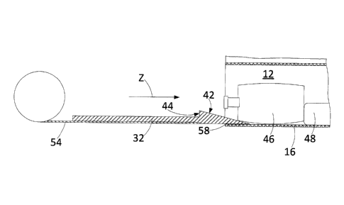
The platform has an upwardly facing cam formation 40 (shown enlarged in the
scrap view of
FIG. 6), the projection having a rear cam face 42 and a forward abutment face
44. To
initiate a pick process, the platform 32 is driven by linkage 34 into the bin
rack as shown in
FIGs. 8 and 9. The platform is at a height at which it slides under the floor
16 of the
selected bin as shown in FIGs. 10 and 11. As the platform is driven into the
bin rack, the
projection 40 passes along the slot 18 in the floor 16 of the selected bin
with a top part of
the projection 40 extending above the upper surface of the floor. A cross
member 45
extending through the projection 40 is positioned so that as the platform 32
enters the bin
7
CA 02768030 2012-01-13
WO 2011/006247
PCT/CA2010/001098
rack, the cross member 45 becomes inserted in the junction between the floor
16 of the bin
and the package to be picked. The cross member 45 has a number of functions.
Firstly, it is
supported by the floor 16 of the selected bin as the platform enters the bin
rack and so acts
to prevent the platform 32 from sagging. The cross member also aids in guiding
the
projection 40 into a proper position for subsequent retrieval of a package
from the selected
bin. The cross member also keeps the package being picked relatively aligned
with the
direction of pick head exit throughout the pick process. Finally, the cross
member is of
value in separating a package from the floor 16 of the selected bin and, in
terms of depth, in
separating a package from an adjacent package within a row of packages.
As alluded to previously, during a package picking cycle, the platform is
driven rearwardly
into the bin rack to pick up a desired package from the selected bin 12 and
then is driven
forwardly out of the bin rack to drag the picked package from the selected
bin. Successive
phases of the platform movement are shown as sectional views in FIGs 8, 10, 11
and 12. In
FIG. 10, the platform 32 has reached a position in its rearward movement in
which the cam
face is starting to lift a pill bottle 46 from the bin floor 16 and also
forcing the bottle to tilt
with the mouth end of the bottle 46 raised above the bin floor. As shown in
FIG. 11, the
platform has moved further rearwardly to a position where it has passed under
the bottle's
centre of gravity and the bottle is repositioned to alter its angle of tilt
relative to the bin
floor. After still further rearward motion of the platform, the platform
reaches a drop
position as shown in FIG. 12 at which the bottle 46, under its own weight,
drops down
against the bin floor with the abutment face 44 located adjacent a trailing
extremity of the
pill bottle 46. At this point, drive to the platform provided by the
telescopic linkage 34 is
reversed. As shown in FIG. 13, as the platform 32 moves forwardly out of the
bin rack, the
abutment face 44 bears against the bottle 46 to drag the bottle out of the
selected bin with
the bottle falling onto the platform and becoming supported by it as the
platform emerges
from the rack.
In the embodiment shown in FIGs. 8 through 13, the package to be picked forms
part of a
row of packages with part of an immediately rearwardly adjacent pill box 48
being shown.
As can be seen, as a result of the lifting and tilling movement of the pill
bottle 46 and pill
box 48 during the course of the pick cycle, the opposed ends of the two
packages are forced
8
CA 02768030 2012-01-13
WO 2011/006247
PCT/CA2010/001098
apart. This has particular value in relation to two common problems in
dispensing packages,
especially in dispensing pill boxes from a row of such boxes.
One problem of dispensing articles such as pill boxes which are relatively
lightweight is that
packages may stick together causing two boxes to be loaded onto the pick head
platform
rather than one package. In the storage bin, two package boxes may be caused
to stick
together if they press against each other for a long period during storage,
especially if the
boxes are made of cardboard and have been subjected to humid conditions. This
increases
the chance that when the pick head lifts one box, it may actually lift both,
creating a double
pick error. The passage of the cam formation 40 completely under the first box
¨ the
package to be picked ¨ and partly under a rearwardly adjacent box tends to
cause a
separation angle to open up between the two packages and, additionally, forces
the packages
incrementally from their stored positions to establish a temporary height
difference at the
interface of the two packages. If the attraction between the stuck faces is
overcome in the
course of the projection passing progressively under the two packages, then
only the package
intended to be picked will be dragged from the selected bin.
A back end storage bin rack such as that shown in FIGs. 1 and 2 may be
implemented with
one standard bin size or, as shown in FIGs. 21 and 22, as a combination of
different bin
sizes enabling packages of diverse shapes and sizes to be stored. In addition,
the storage
bins may hold standard or non-standard sized pill bottles or boxes or other
medicaments
such as bulk medication storage containers, bandages, etc. Some or all of the
storage bins
may be located in a zone of the bin rack which is at room temperature, while
others may be
located in a controlled temperature section such as a refrigerated zone for
proper storage of
medicaments that are prone to deterioration at room temperature. If desired, a
reconstitution, mixing and/or compounding bulk medication storage container
can be
present in an over-large bin, the container housing one or more elements to be
picked by the
pick head.
At the time of a package pick by the control system, the package
characteristics are known
because each package is measured and its dimensions recorded in the course of
the package
being serialized and put into inventory in a selected bin of the bin rack.
Also recorded are
9
CA 02768030 2012-01-13
WO 2011/006247
PCT/CA2010/001098
any or all of the package's weight, shape, moment arm, and other particulars
pertaining to
the location and nature of the package and each of these can be used in the
package handling
control algorithm.
As shown in FIG. 5, sensors 50 at the pick head 20 sense the size of the
package that has
been picked to determine that a single package has been picked and to
determine that there
have been no common errors such as a stuck pick, where the package sits in
place due, for
example, to slipperiness, or a double pick, where two packages in close
proximity are either
tangled or stuck together. The control system, using input from the sensors
and specific
data for the package being picked, determines likely mots and initiates
appropriate control
manoeuvres to try to overcome a problematic pick. Obviously, characteristics
of the
packages other than or in addition to size can be sensed by sensors
incorporated in the pick
head. Such characteristics can include, for example, shape and/or weight.
An alternative design of platform and drive is shown in the embodiment of FIG.
14 to 16.
The platform 32 is fixed to one end of a spool 52 of actuator tape 54. The
tape is a heavy
duty version of retracting tape rule. As is known in the tape rule art, the
actuator tape has a
curved lateral profile. This allows the tape to be readily bent in one
direction to allow
compact storage on the spool 52 when the spool is wound up but resists bending
in the
opposite direction whereby it can drive the platform 32 and a medicament
package
supported by the platform in a pick or load operation when the spool is
unwound. The
platform 32 is somewhat narrower than the platform of the FIG. 8 embodiment
and has an
end region formed with a tapered blade 58 with a cam face 42 and an abutment
face 44
having the same function as the cam and abutment faces, 42, 44, of the
projection 40 in the
FIG. 8 embodiment. This particular embodiment can be used with a bin without a
slotted
floor. In a pick operation, after the pick head 20 reaches the desired XY
position, the spool
52 of actuator tape is driven to unwind the tape 54 so that the platform 32 is
driven
rearwardly towards the selected bin. As best shown in FIG. 16, the platform 32
is brought
to a position where the leading edge of the tapered blade 58 is aligned with
the upper surface
of floor of the selected bin 12 so that further rearward motion of the
platform acts to insert
the tip of the blade between the bin floor 16 and the foremost package stored
in the bin. As
the spool is further unwound, the tapered blade 58 is driven rearwardly along
the floor 16 of
CA 02768030 2012-01-13
WO 2011/006247
PCT/CA2010/001098
the bin with the cam face 42 operating to raise the desired package and with
the platform 32
supported on the floor of the selected bin. The desired package 46 is
prevented from
moving rearwardly in the bin 12 either by the back wall 17 (not shown) or by a
next adjacent
package in a row of such packages which is prevented from rearward motion by
wall 17.
With the rearward motion of the desired package prevented or halted, the
desired package
tides up and over the cam formation 42 onto the platform 32 as the platform is
driven
rearwardly into the selected bin. Subsequently, the platform is withdrawn from
the bin rack
as the spool 52 is rewound so as to withdraw the desired package 46 which is
then supported
by the platform. The abutment face 44 acting on the desired package assists in
the
withdrawal of the package if the force of engagement between the platform
upper surface
and the desired package is insufficient to drag the package out of the bin
rack, or if minor
jamming occurs and must be overcome.
In contrast to the FIG. 8 embodiment, the FIG. 14 embodiment can be readily
utiti7ed for
loading packages into selected bins 12 as an alternative to manual loading. In
the loading
process, a package is loaded onto the platform 32 with the pick/load head 20
located at a
receiving station in the dispensary kiosk. The pick/load head is then operated
to bring the
platform and the package supported by it to the selected bin. The spool 52 is
then unwound
in an operation similar to that taking place in the pick process. As the
platform 32 moves
rearwardly into the selected bin 12, the supported package is driven as far as
is permitted
depending on what other packages are already stored in the bin. Subsequently,
the tape
spool is reversed to retrieve the platform from the selected bin, but only
after a barrier not
shown) mounted on the pick head 20 is moved to a position at which the
platform 32 can
exit the selected bin, but any package supported on the platform is preventing
from being
dragged or driven out of the bin.
A variation of the FIG. 14 embodiment is shown in FIGs. 17 to 19. Ike the FIG.
14
embodiment, the pick head 20 uses a spool drive 52 as shown in FIGs. 18 and
19. Tape at
the pick head inboard end is confined and supported by two retainer plates 60
as the spool
52 is unwound and, similarly to the FIG. 14 embodiment, is supported by the
engagement of
the platform 32 sliding onto the floor of a selected bin at the tape outboard
end. In the
FIG. 17 embodiment, the platform 32 combines features of the FIG. 14 and FIG.
8
11
CA 02768030 2012-01-13
WO 2011/006247
PCT/CA2010/001098
embodiments. Thus the platform 32 is adapted for use with a storage bin having
a front to
rear slot (not shown) of the sort described with respect to the FIG. 8
embodiment. The
platform has an integral web part 62 extending down from a main body part 63
of the
platform, and a rail 64 extending laterally on either side of the web part.
The web part
moves within the bin floor slot as the platform 32 is driven into and out of
the bin rack.
The main body part 63 of the platform slides over the upper surface of the bin
floor and is
supported by it, while the rail 64 slides along the undersurface of the bin
floor. As the
platform nears its home station position in the pick head, the web part 62
moves between
the retainer plates 60 with the rail under edge flanges 66 of the retainer
plates.
The platform has a cam formation 40 which projects above the bin floor but
also has
narrower central section 68 which, in use, extends down into the bin floor
slot. A particular
value of the cam formation is that the leading end of the platform 32 lifts
and slides under
any package that is very thin or that has a thin layer lying adjacent the bin
floor which is
encountered by the platform as it moves into the storage rack.
As mentioned with respect to the FIG. 14 embodiment, at certain junctures in
the package
picking and loading procedures, it is desirable to withdraw the platform 32
without
withdrawing a package that is supported on the platform, or without
withdrawing such a
package any further than a predetermined position. As shown in FIG. 17, a
barrier
arrangement is provided by spaced plates 70 which can be driven
perpendicularly to the pick
head Z-axis to increase and decrease the spacing of the plates.
In operation, during a package loading procedure, the platform supporting the
package to be
loaded is driven into the bin rack. Once the package is in place, the plates
70 are driven to
reduce their spacing and the platform 32 is withdrawn from the bin rack. The
platform
slides under lower edges 72 of the plates towards its home station in the pick
head while the
package which has been loaded in the selected bin and hitherto supported by
the platform is
blocked from exiting the selected bin by vertical edges 74 of the plates 70.
The platform has
a radiused rear formation 76 to reduce the risk of jamming of a package
against the barrier as
the platform 32 travels out of the bin rack. The plates have adjunct functions
to both grip a
12
CA 02768030 2012-01-13
WO 2011/006247
PCT/CA2010/001098
package which has been picked from the bin rack when the picked package
reaches a desired
position in the pick head and also to centre the package in the pick head.
As previously mentioned, packages may be stored in a bin rack either with one
package in a
bin, or with a row or stack of packages in a bin. The manipulation of a row of
packages has
already been described with reference to the illustrated embodiments. In the
case of a
vertical stack of packages, the pick head platform and a barrier of the sort
described with
respect to FIG. 17 can be used to pick and extract the lowermost package in
the stack,
allowing upper members of the stack to drop. Similarly, a combination of
camming and
abutment formations together with a barrier of the sort described platform can
be used to
enable a package to be loaded under a resident stack of packages within a
storage bin. In
addition if it is desired to pick or place a package in an intermediate
position in a stack or
row, the pick head can be used to pick and temporarily park packages from a
stack or row in
an adjacent bin until a desired package is exposed for picking or until a
desired location is
exposed for loading.
Although in the preferred embodiments described herein, the bins are located
in a rack as an
array of rows and columns, other arrays are possible such as a radial array or
a diagonal array.
In such arrays, the rectangular form of bin may not be optimal and alternative
bin shapes
may be of advantage. In such alternative embodiments, the lower wall or floor
of the bin
may not extend hori7ontally or may not extend horizontally over its full
extent. In
addition, while it is convenient to have a pick head that moves in a Z
direction in relation to
a bin rack generally mounted in an XY plane, the pick head drive may be
implemented to
effect a movement of the pick head into the bin rack in a locus which is not
linearly along a
z-axis. For example, the pick head is moved over an arcuate path or packages
are held in
one position and then twisted into a desired position as they are loaded or
withdrawn from a
storage bin.
In the embodiments described, packages in a bin are acted upon by gravity and
this
interaction of the stored packages with the platform upper surface, the
abutment edges and
cam formations permits a ready and simple implementation of platform entry and
exit to
effect picking and loading of a package relative to a selected bin. While the
effect of the
13
CA 02768030 2012-01-13
WO 2011/006247
PCT/CA2010/001098
packages' own weight is convenient, the effect of gravity may be replaced by
or
supplemented by having a stored package acted upon by a bias such as a spring
bias. Such a
bias can be applied permanently while the package is in a bin or at the pick
head or may be
acted upon in the course of platform movement into and out of the bin rack. In
such an
arrangement, cam and/or abutment formations may act in a manner similar to the
illustrated
embodiments, but the package to be picked or loaded is moved against and by
the action of
the bias as opposed to or in addition to gravity.
Other variations and modifications will be apparent to those skilled in the
art. The
embodiments of the invention described and illustrated are not intended to be
limiting. The
principles of the invention contemplate many alternatives having advantages
and properties
evident in the exemplary embodiments.
14