Note: Descriptions are shown in the official language in which they were submitted.
CA 02768031 2012-02-08
TITLE: MODULAR APPARATUS FOR PRODUCTION TESTING
FIELD OF THE INVENTION
[0001] The present application relates to the oil and gas well testing, and
more
particularly to a modular apparatus for production testing.
BACKGROUND OF THE INVENTION
[0002] Production well testing comprises a process for acquiring data on new
and
existing wells, for example, oil and gas wells. The types of determinations
that may be
made by well operators include: geophysical boundaries, flow rates, maximum
flow rate,
zone permeability, reservoir pressure, gas and effluent sampling, and zonal
contribution.
[0003] Production well testing apparatus typically comprises a cylindrical
pressure
vessel separator configured in either a horizontal or a vertical orientation.
The pressure
vessel can be used in a number of exploratory and remedial applications,
including the
following: formation effluent clean-up, well bleed-off, pipeline bleed-off,
well start-up,
gas flaring, work-overs and under balanced drilling.
[0004] Production well testing equipment is typically configured on a skid or
as a
trailer mount unit which is transported via heavy duty truck tractors on
established road
networks proximate to the well site. Because of the requirement for road
transportation,
there are also seasonal limitations for dry seasons or winter periods when the
ground is
frozen. For example, in northern climes, such as Canada or Alaska, temporary
roads may
be built over the frozen ground or lakes in the winter.
CA 02768031 2012-02-08
-2-
[0005] It will be appreciated that the seasonal restrictions on the movement
of
production well testing equipment using conventional techniques gives rise to
a number
of problems for well operators including, limited availability of service
companies for
production well testing, dealing with extreme weather conditions, higher costs
and the
over-extension of operational and logistical resources, diminished
productivity.
[0006] Accordingly, there remains a need for improvements to address the
shortcomings associated with conventional production testing equipment in the
art.
BRIEF SUMMARY OF THE INVENTION
[0007] The present application comprises a modular apparatus for production
testing.
According to one aspect, the apparatus is suitable for transport and assembly
in the field.
According to another aspect, the apparatus comprises one or more substantially
spherical
pressure vessels. According to another aspect, the apparatus comprises one or
more semi-
spherical pressure vessels.
[0008] According to one embodiment, the present invention provides a modular
apparatus for production testing at a field site, the apparatus comprises: a
platform, the
platform including one or more mounting brackets; one or more pressure
vessels, each of
the one or more pressure vessels including a support member for each of the
one or more
mounting brackets; and each of the one or more mounting brackets includes a
guide
configured to guide the support member into position from an elevated
position.
[0009] According to another embodiment, the present invention provides a
production testing apparatus comprising: a platform having one or more
mounting
brackets; and one or more spherical pressure vessels, each of the one or more
spherical
CA 02768031 2012-02-08
-3-
pressure vessels including a mounting member for a corresponding one of each
of the one
or more mounting brackets.
[00010] According to yet another embodiment, the present invention provides a
method for assembling a modular production testing apparatus at a field site,
the modular
production testing apparatus includes a platform and one or more pressure
vessels, the
method comprises the steps of. locating the platform at the field site;
suspending each one
of the pressure vessels above the platform; aligning the pressure vessel above
a guide
mechanism on the platform; lowering the pressure vessel onto the guide
mechanism to a
seated position.
[00011] Other aspects and features according to the present application will
become
apparent to those ordinarily skilled in the art upon review of the following
description of
embodiments of the invention in conjunction with the accompanying figures.
BRIEF DESCRIPTION OF THE DRAWINGS
[00012] Reference will now be made to the accompanying drawings which show, by
way of example, embodiments according to the present application, and in
which:
[00013] Fig. 1 shows a platform or base for a modular apparatus for production
testing
according to an embodiment of the present invention;
[00014] Fig. 2(a) is a top view of the base or platform of Fig. 1 according to
an
embodiment of the present invention;
CA 02768031 2012-02-08
-4-
[00015] Fig. 2(b) is a side view of the base or platform of Fig. 1 according
to an
embodiment of the present invention;
[00016] Fig. 2(c) is an end view of the base or platform of Fig. 1 according
to an
embodiment of the present invention;
[00017] Fig. 3(a) shows a platform or base for a modular apparatus for
production
testing according to another embodiment of the present invention;
[00018] Fig. 3(b) is a top view of the base or platform of Fig. 3(a) according
to an
embodiment of the present invention;
[00019] Fig. 3(c) is a side view of the base or platform of Fig. 3(a)
according to an
embodiment of the present invention;
[00020] Fig. 3(d) is an end view of the base or platform of Fig. 3(a)
according to an
embodiment of the present invention;
[00021] Fig. 4 shows in diagrammatic form a spherical vessel for a modular
apparatus
according to an embodiment of the invention;
CA 02768031 2012-02-08
-5-
[000221 Fig. 5 shows in diagrammatic form a spherical vessel for a multiple
vessel
implementation of a modular apparatus according to an embodiment of the
invention;
[000231 Fig. 6 shows in diagrammatic form a spherical vessel for a multiple
vessel
implementation of a modular apparatus according to an embodiment of the
invention;
[000241 Fig. 7 shows in schematic form a modular apparatus having an
arrangement of
three spherical vessels according to an embodiment of the invention;
[00025) Fig. 8 shows a rear view of the modular apparatus of Fig. 7 according
to an
embodiment of the invention; and
[000261 Fig. 9 shows a top view of the modular apparatus of Fig. 7 according
to an
embodiment of the present invention.
[000271 Like reference numerals indicate like or corresponding elements in the
drawings.
DETAILED DESCRIPTION OF THE EMBODIMENTS
[000281 The present invention is directed to embodiments of a modular
apparatus for
production testing according. The modular production testing apparatus
comprises a base
(i.e. skid) or platform 110, according to one embodiment, as shown in Figs. 1-
2 and one
or more pressure vessels 400, for example, as shown in Figs. 4 to 6. According
to one
CA 02768031 2012-02-08
-6-
embodiment, the pressure vessel(s) 400 (500, 600) comprises a spherical tank
as shown
in Fig. 4 (Figs. 5 and 6) and described in more detail below. According to
another
embodiment, the pressure vessel 400 comprises a semi-spherical tank design.
[000291 Referring to Figs. 1 to 2, the base or platform 110 comprises a tank
alignment
insert or guide mechanism and support member for mounting one or more of the
pressure
vessels. As shown, the base or platform 110 comprises a base member 112 and
one or
more mounting brackets 114, indicated individually by references 114a and
114b,
respectively. The mounting brackets 114 are configured to receive and hold the
base or
support members 420 and 422 of the pressure vessel 400, for example, as shown
in Fig.
4. As shown in Figs. 1 and 2(a), the base member 112 may be constructed as a
frame
comprising longitudinal members 140, indicated individually by references 140a
and
140b in Fig. 1, and cross members 142, indicated individually by references
142a, 142b,
142c, 142d and 142e in Fig. 1. The longitudinal members 140 and the cross
members 142
may comprise structural steel or aluminum components which are welded or
fastened
together using other known techniques. The base member 112 depicted in Fig. 2
is
configured for three pressure vessels (for example, pressure vessels 400, 500
and 600 as
shown in Figs. 4, 5 and 6, respectively) and as such comprises extended
longitudinal
members 140 and includes additional cross members 142f, 142g, 142h, 142i and
142j. As
also shown in Fig. 2(b), the base 110 also includes a lug 116 at each corner.
The lugs 116
are configured to receive an eye-bolt or other fasteners suitable for
attaching a sling or
lifting hooks. The pressure vessels 400, 500, 600 also attachment points for a
sling, hook
or other lifting mechanism, for example, attachment rings 522 as shown in Fig.
5.
According to one aspect, this configuration allows the base to be easily
lifted or
maneuvered, for example, onto a flat bed trailer, and also makes it suitable
for transport
by helicopter to remote locations or sites not readily accessible by road or
ground
transport.
CA 02768031 2012-02-08
-7-
[00030] According to an embodiment of the invention, each of the mounting
brackets
114 comprises a trough or guide configuration which is dimensioned to receive
and seat a
corresponding base support member 420, 422 (for example, a rail) on the
pressure vessel
400 depicted in Fig. 4, and described in more detail below. As shown in Fig. 1
and Fig.
2(c), each of the mounting brackets 114 comprises a support base 120 and an
insert or
alignment member 130. According to one embodiment, the insert or alignment
member
130 comprises a pair of outwardly slanting or angled walls or members
indicated by
references 132 and 134, respectively. The V-shaped trough formed by the angled
walls
132 and 134 serve to guide or align the pressure vessel on the platform 110,
i.e. by
moving the base or rail members of the vessel into alignment with the support
base 120,
as the vessel is being lowered, for example, by a crane or by a sling attached
to a
helicopter. As the pressure vessel is lowered the angled walls 132, 134
function to guide
the pressure vessel into position until the base support member (e.g. rails
420 and 422 in
Fig. 4) is seated or resting on the support base 120. According to this
embodiment the
base support members or rails on the base of the pressure vessel are aligned
in parallel,
i.e. along the longitudinal axis of the mounting brackets 114. According to
another
embodiment, the alignment member 130 comprises a single outwardly slanting or
angled
wall as described in more detail below with reference to Fig. 3.
[00031] Referring back to Fig. 1, the angled configuration of the mounting
brackets
114 further facilitates the assembly of the apparatus 100 in the field. For
example, the
platform 110 is transported by helicopter, i.e. "heliported", to the field
site and placed on
the ground. Next, the spherical pressure vessel 400 is heliported to the site
and the vessel
400 is positioned over the platform 110, lined up with the mounting brackets
114 and
lowered into place. The configuration of the mounting brackets 114 (i.e. the
outwardly
angled walls) allow the pressure vessel 400 to be guided into place under the
force of
gravity and with minimal intervention or guiding by personnel positioned under
the
helicopter, which as will be appreciated can be a dangerous working
environment or
situation. It will be appreciated that according to one aspect, the self
aligning insertion
brackets 114 and the mounting or seating trough facilitate the positioning and
mounting
CA 02768031 2012-02-08
-8-
of the individual pressure vessels thereby improving worker safety while
working under
suspended loads. The platform 110 depicted in Figs. 1 to 3 is configured for a
three
pressure vessel application, for example, as described in more detail below
with reference
to Figs. 7 to 9. According to another embodiment, the platform 110 may be
configured
for single vessel configuration. To facilitate the transport and assembly, the
pressure
vessels also include multiple lift point attachments, for example, lugs or
fastening means
for accepting eye-bolts or other types of connectors for lifting the vessels,
for example,
on a sling under a helicopter.
[000321 Reference is next made to Figs. 3(a) to 3(d) which depict a platform
or skid
according to another embodiment of the invention. The platform or skid is
indicated
generally by reference 300, and similar to the platform 110 described above,
the platform
300 comprises a pair of longitudinal members 140a and 140b and frame or cross
members 142a to 142j. The platform or skid 300 includes mounting brackets 314,
indicated individually by references 314a and 314b, respectively. The mounting
brackets
314 are configured to receive and hold the base or support members 420 and 422
of the
pressure vessel 400, for example, as shown in Fig. 4, or a base member 520 as
shown in
Fig. 5 for the pressure vessel 500. In accordance with this embodiment, the
mounting
brackets 314 comprise a support base 320 and a guide or alignment member 330.
According to this embodiment, the guide or alignment member 330 comprises a
single
outwardly slanting or angled wall or member indicated by references 332. The
outwardly
slanting or angled wall 332 forms a slope which functions to guide or align
the pressure
vessel on the platform 300, i.e. by moving the base or rail members of the
vessel into
alignment with the support base 320, as the vessel is being lowered, for
example, by a
crane or by a sling attached to a helicopter. As the pressure vessel is
lowered, the rails of
the pressure vessel slide along the angled wall 332 into position until the
rails are seated
or resting on the respective support bases 320.
CA 02768031 2012-02-08
-9-
[00033] As shown in Fig. 3(d), the mounting brackets 314 for the platform 300
may
include an insert 334 according to an embodiment. The insert 334 may be formed
from a
plate of steel or other structural material which is then hardened or
otherwise treated for
abrasion resistance and durability. As shown, the hardened insert 334 can be
formed to
extend across the angled wall 332 and down across the support base 330.
According to
another embodiment, the insert 334 may comprise two separate plates or
sections, with
one section fastened to the angled wall 332 and the other section fastened to
the support
base 330. According to another embodiment, the insert 334 is fastened or
attached to the
mounting bracket 314 with removable fasteners, such as bolts, to provide the
capability to
replace the insert 334 for wear and tear. According to another embodiment, an
insert may
be provided for the mounting brackets 114 described above the platform 110 of
Fig. 1.
[00034] Reference is next made to Fig. 4, which shows a pressure vessel
according to
an embodiment of the invention. The pressure vessel is indicated generally by
reference
400 and according to an embodiment comprises a spherical configuration or
vessel. As
shown and according to an embodiment, the spherical pressure vessel 400
includes an
inlet connection flange 402, for coupling to output line, for example, on a
well-bore for
an oil or a gas well. The spherical pressure vessel 400 includes a connection
flange 404
and a connection flange 406 for connecting to a mating pressure vessel in a
multi-vessel
configuration 700 for example as shown in Fig. 7. As shown, the spherical
pressure
vessel 400 also includes a Pressure Safety Valve or PSV connection flange 408,
and a
drain connection flange 410. The pressure safety valve prevents the vessel
from being
over pressured, i.e. beyond its Maximum Pressure Rating or MPR. For the three
vessel
configuration of Fig. 7, the pressure safety value would be set around 740
psi. The
pressure safety valves are typically coupled or "tied" into a "Gas Out" or
flare line in
order to contain any hydrocarbons that may be released, i.e. prevent the
hydrocarbons
from being released into the atmosphere.
CA 02768031 2012-02-08
-10-
[00035] Reference is next made to Fig. 5, which shows a pressure vessel
suitable for a
multiple vessel configuration according to an embodiment of the invention. The
pressure
vessel is indicated generally by reference 500 and comprises a spherical
configuration.
According to an embodiment, the spherical pressure vessel 500 is intended to
couple
between the pressure vessel 400 (Fig. 4) and another pressure vessel 600 (Fig.
6) in a
multiple vessel configuration or arrangement 700 as depicted in Fig. 7. As
shown in Fig.
5, the spherical pressure vessel 500 includes a connection flange 502 and a
connection
flange 504. As shown in Fig. 7, the connection flanges 502 and 504 couple or
connect to
the corresponding connection flanges 404 and 406 on the spherical pressure
vessel 400
(Fig. 4). The spherical pressure vessel 500 includes a PSV connection flange
508, and a
drain connection flange 510. In order to couple with a second pressure vessel
(for
example, the pressure vessel 600 as depicted in Fig. 7), the pressure vessel
500 includes a
connection flange 503 and a connection flange 505. As shown in Fig. 7, the
connection
flanges 503 and 505 couple or connect to corresponding connection flanges 602
and 606
on the spherical pressure vessel 600 (Fig. 6).
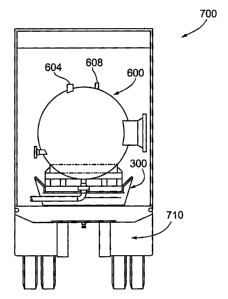
[00036] Reference is next made to Fig. 6, which shows another pressure vessel
suitable for connection in a multiple vessel configuration, for example, as
depicted in Fig.
7. The pressure vessel is indicated generally by reference 600 and according
to an
embodiment comprises a spherical configuration or vessel. As shown, the
spherical
pressure vessel 600 includes an input connection flange 602 and an input
connection
flange 606 for connecting to the respective output connection flanges 503 and
505 on the
second or middle pressure vessel 500, for example as shown in Fig. 7. As
shown, the
spherical pressure vessel 600 also includes a gas-out connection flange 604
and a PSV
connection flange 608. The pressure vessel 600 also includes a drain
connection flange
610. The drain connection flange 610 may be coupled to a steam coil 612 as
indicated in
Fig. 7. In a single pressure vessel configuration, the connection flange 402
would
function as the inlet and the other connection flange 606 would be capped or
otherwise
sealed.
CA 02768031 2012-02-08
-11-
[00037] According to one embodiment, the pressure vessels 400, 500 and 600
comprise 2.5 m3 vessels and the flange connections 404 to 502, 406 to 506, 503
to 602
and 505 to 606 comprise 600 ANSI flanges. This configuration provides the
equivalent of
a conventional trailer mounted 740 psi, 7.5 m3 unit, with the added benefit
that the
modular components, i.e. the platform 110 and the pressure vessels 400, 500,
600 are
heliportable and can be transported separately by helicopter to a field site
and assembled.
[00038] According to an aspect of the invention, the modular design of the
production
testing apparatus 100 provides a configuration which allows the components of
the
apparatus 100, i.e. the platform base 110 and the pressure vessels 400, 500
and/or 600, to
be transported individually or in unassembled form into the field and then
assembled or
configured in the field. With the weight reductions resulting from the modular
design, the
components can be transported separately and reassembled at the worksite in
the field.
According to another embodiment, the pressure vessels are assembled or
configured on a
trailer and the trailer is transported by road to a site or a staging area for
helicopter
transport, as described in more detail below with reference to Figs. 7 to 9.
At the staging
area, the pressure vessels are taken off the trailer and individually
transported by
helicopter to the worksite and reassembled on a skid at the worksite.
[00039] Reference is next made to Figs. 7 to 9 which show a configuration for
a multi-
vessel apparatus according to an embodiment of the present invention. The
multi-vessel
apparatus is indicated generally by reference 700. In accordance with this
embodiment,
the platform or skid 300 is mounted on a flat-bed trailer indicated by
reference 710 and
the three pressure vessels 400, 500 and 600 are seated in the respective
mounting
brackets 314a and 314b as described above with reference to Fig. 3. The three
pressure
vessels 400, 500, 600 are also coupled together to allow the apparatus 700 to
be moved to
a field site and coupled to a well. According to another aspect, the apparatus
700 can be
CA 02768031 2012-02-08
-12-
moved to a staging area and disassembled for transport by helicopter to a more
remote
field site or a field site not accessible by road for a tractor and flat-bed
trailer.
[00040] As shown in Fig. 7, the inlet connection flange 402 on the pressure
vessel 400
is coupled to an output line 720. The output line 720 couples the inlet to a
well bore at a
field site. The connection flanges 404 and 406 of the pressure vessel 400 are
coupled to
the respective connection flanges 502 and 506 of the second pressure vessel
500.
Similarly, the connection flanges 503 and 505 of the second pressure vessel
500 are
coupled to the respective connection flanges 602 and 606 of the third pressure
vessel 600.
The "gas-out" connection flange 604 on the third pressure vessel 600 is
coupled to an
input line 742 on a production well testing module or unit indicated generally
by 740.
The production well testing module 740 is implemented in known manner to
provide the
capability for acquiring data for determining well characteristics or
parameters, such as,
flow rates, maximum flow rates, zone permeability, reservoir pressure, gas and
effluent
sampling, and other parameters or characteristics as will be familiar to those
skilled in the
art.
[00041] Referring again to Fig. 7, the production well testing module 740 may
also
include a gas-out flare line indicated generally by reference 750. The gas-out
flare line
750 includes flange connectors 752a, 752b, 752c which connect to the
respective PSV
(Pressure Safety Valve) connection flanges 408, 508, 608 on the respective
pressure
vessels 400, 500 and 600. In known manner, the pressure safety valves prevent
the
pressure vessels from becoming over pressurized, i.e. beyond the vessel's
maximum
pressure rating. The gas-out flare line 750 allows any releases from the
pressure vessels
to be contained. The respective drain connection flanges 410, 510 and 610 for
the
pressure vessels 400, 500 and 600 may be coupled to a steam coil (not shown).
CA 02768031 2012-02-08
-13-
[00042] According to another aspect of the invention, the spherical
configuration of
the pressure vessels 400, 500 or 600 provides a tank or vessel design which is
approximately twice as strong as a cylindrical pressure vessel. This means
that the wall
thickness of the spherical pressure vessel 400, 500, 600 can be reduced to
provide further
weight savings, thereby making the pressure vessels 400, 500, 600 and the
platform base
110 (or 300) suitable for helicopter transport and field assembly.
[00043] As described above with reference to Figs. 1 to 2, the base or
platform 110
according to an embodiment includes the mounting brackets 114. According to an
aspect
of the invention, each of the mounting brackets 114 comprises a trough
configuration
which is dimensioned to receive and seat a corresponding base support member
on the
pressure vessel. For example, as shown in Fig. 4, the spherical pressure
vessel 400
includes a pair of base support members 420 and 422. As shown in Figs. 1 to 2,
the
mounting brackets 114 are raised above the platform 110 (i.e. the base 112) to
accommodate fittings on the underside of the vessel 400, for example, the
drain flange
connection 410.
[00044] Referring back to Fig. 1, the angled configuration of the mounting
brackets
114 further facilitates the assembly of the apparatus 700 in the field. For
example, the
apparatus 700 is transported on the trailer 710 to a staging area. At the
staging area, the
pressure vessels 400, 500, 600 and the platform 110 are disconnected and the
vessels are
removed from the platform 110. The platform 110 is then lifted and transported
by
helicopter, i.e. "heliported", to the field site and placed on the ground.
Next, the spherical
pressure vessel 400 is heliported to the site and the vessel 400 is positioned
over the
platform 110, lined up with the mounting brackets 114 and lowered into place.
The
configuration of the mounting brackets 114 (i.e. the outwardly angled walls)
allow the
pressure vessel 400 to be guided into place under the force of gravity and
with minimal
intervention or guiding by personnel positioned under the helicopter, which as
will be
appreciated can be a dangerous working environment or situation. It will be
appreciated
CA 02768031 2012-02-08
-14-
that according to one aspect, the self aligning insertion brackets 114 and the
mounting or
seating trough facilitate the positioning and mounting of the individual
pressure vessels
thereby improving worker safety while working under suspended loads. To
facilitate the
transport and assembly, the pressure vessels also include multiple lift point
attachments,
for example, lugs or fastening means for accepting eye-bolts or other types of
connectors
for lifting the vessels, for example, on a sling under a helicopter.
[00045] The present invention may be embodied in other specific forms without
departing from the spirit or essential characteristics thereof. Certain
adaptations and
modifications of the invention will be obvious to those skilled in the art.
Therefore, the
presently discussed embodiments are considered to be illustrative and not
restrictive, the
scope of the invention being indicated by the appended claims rather than the
foregoing
description, and all changes which come within the meaning and range of
equivalency of
the claims are therefore intended to be embraced therein.