Note: Descriptions are shown in the official language in which they were submitted.
CA 02768124 2014-04-03
,
WATER-RESISTANT WHILE-IN-USE ELECTRICAL BOX
BACKGROUND INFORMATION
100011 Electrical boxes are often mounted vertically in walls prior to
completion of the
wall structure to provide a housing for electrical devices and wiring that may
be used for
telephone, video, and networking, among other utility and communication uses.
For example,
an electrical box may be mounted on a wall stud prior to drywall installation,
thus providing
an electrical housing within the wall for the termination of electrical cable
and the connection
of the cable wiring to a mounted electrical outlet.
[0002] In potentially wet environments, electrical boxes are often
mounted vertically to a
wall or other structure to supply electricity. Some traditional installations
may provide a box
that houses an electrical outlet mounted to the vertical surface of an
exterior wall. A cover
may be provided over outdoor electrical outlet receptacles to help protect the
outlet from
moisture and other environmental conditions. The cover allows access to the
outlet
receptacles in order to plug in a male electrical fitting of an electrical
cord or device into a
receptacle. In some installations the electrical box may be mounted within the
exterior wall
and a cover provided over the outlet receptacles.
SUMMARY OF THE INVENTION
[0002.1] In accordance with one aspect of the present invention, there is
provided an
electrical box, comprising a housing enclosing a space and including an inner
opening to the
enclosed space, and a cover panel over the inner opening, the cover panel
including a wall
1
CA 02768124 2014-04-03
projecting from one side of the cover panel, the wall surrounding a panel
opening in the cover
panel, a shielding cap, having an open side therein, to be placed over the
wall and coupled to
the one side of the cover panel when the electrical box is in a first
configuration, and a sealing
door to block the panel opening at the other side of the cover panel when the
electrical box is
in a second configuration, wherein the cover panel is configured to cover the
housing, the one
side of the cover panel facing outside of the electrical box when the
electrical box is in the
first configuration, and cover the housing, the other side of the cover panel
facing the outside
of the electrical box when the electrical box is in the second configuration.
[0002.2] In accordance with another aspect of the present invention, there is
provided a
method, comprising opening a cover panel of an electrical box, the cover panel
having one
side with an opening surrounded by a wall projecting from the cover panel,
inserting a cable
through the opening into an enclosed space of the electrical box, placing the
cover panel over
the electrical box such that the one side faces outside of the electrical box,
and placing a
shielding cap over the wall to attach the shielding cap to the one side of the
cover panel,
wherein the placing the shielding cap comprises pressing the shielding cap to
drive a bottom
edge of the shielding cap, against a first segment of the cable toward the one
side of the cover
panel, forming a first bend on the first segment, and pressing the shielding
cap to push a
second segment of the cable against a top of the wall, forming a second bend
on the second
segment, and wherein the second segment of the cable connects to a cable
portion in the
enclosed space of the electrical box.
[0002.3] In accordance with a further aspect of the present invention, there
is provided an
electrical box comprising a panel coupled to a top side of the electrical box,
the panel
la
CA 02768124 2014-04-03
including a wall on one side of the panel, the wall surrounding a well, in the
first panel, into a
space in the electrical box, and a cap to be placed over the wall and the
well, wherein the cap
and the well are configured to form a first bend and a second bend on a cable
that extends
from outside of the electrical box to an inside space of the electrical box,
the first bend
including a locally lowest point on cable portions that are outside of an area
under the cap.
lb
CA 02768124 2012-02-15
BRIEF DESCRIPTION OF THE DRAWINGS
[0004] Fig. 1 illustrates concepts that are described herein;
[0005] Fig. 2 illustrates a front top isometric view of an exemplary
electrical box in one
configuration;
[0006] Fig. 3 is a front bottom isometric view of the electrical box of
Fig. 2;
[0007] Fig. 4 is a front top isometric view of the electrical box of Fig.
2, with the cover
panel separated from the electrical box;
[0008] Fig. 5 is a front top isometric view of the electrical box of Fig.
1, with the sealing
door separated from the cover panel;
[0009] Fig. 6 is a bottom isometric view of the shielding cap and cover
panel of Fig. 2 and
the sealing door of Fig. 5;
[0010] Fig. 7 is a front top isometric view of the shielding cap, cover
panel, sealing door,
and housing of the electrical box of Fig. 2 in a second configuration;
[0011] Fig. 8 is a front top isometric view of the electrical box of Fig.
2, with the shielding
cap and the cover panel assembled;
[0012] Fig. 9 is a bottom isometric view of the cover panel of the
electrical box of Fig. 2
and the shielding cap of Fig. 7;
[0013] Fig. 10 is a partially exploded front top isometric view of the
electrical box of Fig.
2 configured for use;
[0014] Fig. 11 is an assembled front top isometric view of the electrical
box of Fig. 10;
[0015] Figs. 12A through 14B are front top isometric views of the
electrical box of Fig. 2
with the shielding cap in different orientations;
2
CA 02768124 2012-02-15
=
[0016] Fig. 15 is a cross-sectional side view of the electrical box
of Fig. 2 in the
configuration illustrated in Fig. 11;
[0017] Fig. 16 is an isometric view of different components of the
electrical box of Fig. 2;
and
[0018] Fig. 17 is a flow diagram of an exemplary process for
weatherproofing electrical
devices.
DETAILED DESCRIPTION OF PREFERRED EMBODIMENTS
[0019] The following detailed description refers to the
accompanying drawings. The same
reference numbers in different drawings may identify the same or similar
elements.
[0020] As described herein, an electrical box may be conveniently
installed in or on
structures (e.g., floor, wall, beams, etc.) in an indoor or outdoor
environment. The electrical
box may be installed on structures (e.g., floor) and be arranged in one of two
configurations.
In one configuration, one side of a cover panel of the electrical box may be
placed on the top
of the electrical box, such that the top surface of the electrical box and the
surface of the
structure form a relatively flat plane. This may allow, for example, a user to
mop over the
plane. In another configuration, the other side of the cover panel of the
electrical box may be
placed on the top of the electrical box. In this configuration, the cover
panel provides for
cables, cord, or electrical wires to be connected to devices inside the
electrical box via an
opening.
[0021] As described below, the exemplary configurations may prevent
water, which may
originate from outside of the electrical box, from migrating into and through
the electrical box
3
CA 02768124 2012-02-15
,
to the devices/components and wiring mounted therein. Implementations
described herein
may also provide an electrical box that accommodates an electrical fitting,
such as a male two
or three-pronged plug, as well as cable or cord extending from the electrical
fitting to areas
external to the electrical box. This may allow for electrical connection from
the
devices/components to the exterior of the electrical box, while protecting the
enclosed
devices/components and the electrical connection extending from the
devices/components.
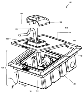
[0022] Fig. 1 illustrates concepts that are described herein. Fig. 1
shows an exemplary
electrical box 100 in a partially assembled configuration. Electrical box 100
may be
associated with one or more electrical functions (e.g. a switch box, a gang
box, an outlet box,
etc.) and may provide an enclosure for one or more devices and/or components
described
herein. The devices or components may be electrical devices/components and
have associated
wiring, wireless connections or circuitry. The devices/components may also
have one or more
applications for electrical power supply, telephone, video, or networking,
among other utility
and communication uses.
[0023] In the following, different orientations or directions are
referred to with respect
to a xyz-axis 124. As used herein, a direction toward the front of electrical
box 100 is in
the direction of +x axis, a direction toward the top is in +z direction, and
the direction
toward "front side" is in +y direction.
[0024] As shown, electrical box 100 includes a shielding cap 102, a cover
panel 104, and
housing 106. Shielding cap 102, when attached to cover panel 104, provides a
protective
cover to an opening 110 into electrical box 100. Cover panel 104 covers the
top of housing
106. Cover panel 104 includes opening 110 and well wall 108. Through opening
110, an
4
CA 02768124 2012-02-15
electrical cable/cord 120 may pass through from the exterior of electrical box
100 into an
interior volume of housing 106. Well wall 108 is perpendicularly attached to
or integrally
formed upon one surface of cover panel 104 and surrounds opening 110. Well
wall 108 may
serve as a protective barrier against elements and/or other materials (e.g.,
water, cleaning
agent, snow, rain, sleet, dirt, leaves, trash, etc.). In addition, as
described below in greater
detail, well wall 108 may operate together with shielding cap 102, when
electrical box 100 is
assembled for use, in placing a bend on a particular portion of electrical
cord or cable 120 that
runs from the exterior of electrical box 100 into the enclosed volume therein.
[0025] Housing 106 may include a frame panel 112 and body 114. Frame panel
112
provides a frame into which cover panel 104 may be placed or fitted. Frame
panel 112
includes an opening 116 through which ingress electrical plug 122 (which also
passes through
opening 110 in cover panel 104) may pass, into the space within body 114. Body
114 may
enclose electrical devices or components, such as for example, electrical
receptacle/outlet 118,
communication devices, switches, etc. In Fig. 1, inside the space in body 114,
electrical
plug/connector/adaptor 122 is illustrated as inserted into receptacle/outlet
118. Shielding cap
102, cover panel 104, and housing 106 may be made of plastic, molded metal,
etc.
[0026] To assemble electrical box 100, after adaptor 122 is inserted into
receptacle 118,
shielding cap 102 may be placed over well wall 108 of cover panel 104, thus
roofing opening
110. Furthermore, cover panel 104 may be fitted into frame panel 112. When
assembled,
shielding cap 102 and well wall 108 protect electrical box 100 from external
materials or
elements. Because opening 110 is protected by shielding cap 102 in this
configuration, the
elements may not enter electric box 100, except through an open side 126. On
open side 126,
CA 02768124 2012-02-15
,
,
however, well wall 108 operates as a barrier against external elements from
entering electrical
box 100.
[0027] Fig. 1 provides an overview of electrical box 100 and its
one exemplary use.
Accordingly, Fig. 1 does not show some components of electrical box 100.
Furthermore, in
the above, some components shown in Fig. 1 are not fully described for
simplicity. In the
following description, electrical box 100, different implementations of
electrical box 100,
their components, and their uses are described in greater detail with
reference to Figs. 2
through 17.
[0028] Fig. 2 illustrates a front top isometric view of electrical
box 100 in a second
configuration. In the configuration, as shown in Fig. 2, cover panel 104 of
Fig. 1, which is
reversible, is flipped over and fitted into frame panel 112.
[0029] As shown, cover panel 104 includes a sealing door 202 and
bottom surface 204.
Bottom surface 204 is the flipside of cover panel 104's surface illustrated in
Fig. 1. Bottom
surface 204 includes opening 110 (also shown in Fig. 1), into which sealing
door 202, in the
shape of rectangle, square, or any geometrical shape, is fitted. In the
configuration shown in
Fig. 2, sealing door 202 may keep elements out of electrical box 100.
[0030] Frame panel 112 includes a flap 206, flange 210, and frame
walls 208. Flap 206
(e.g., a flat piece of material) may fit into a recessed area in frame panel
112. When placed in
the recess, flap 206 overlaps a portion of cover panel 104. In one
implementation, a screw
through flap 206 and frame panel 112 may be tightened to couple one end of
cover panel 104
to frame panel 112.
6
CA 02768124 2012-02-15
,
,
[0031] Flange or rim 210 may extend outwardly or laterally from a
top of frame panel 112.
Frame walls 208, which surround body 114 of housing 106, extend
perpendicularly and
downwardly from the bottom surface of flange/rim 210. Both flange/rim 210 and
frame walls
208 may provide additional rigidity and strength to frame panel 112.
[0032] In some implementations, flange 210 and frame walls 208 may
cooperate in a
combination to facilitate the installation of electrical box 100. For example,
to mount
electrical box 100 in a floor, a hole having the dimensions of frame walls 208
may be made in
the floor. Electrical box 100 may be dropped therein. Flange 210 may hold
electrical box
from falling through the hole by abutting against the floor surface.
[0033] Body 114 may include five sides/walls that form an
enclosure, including four side
walls and a bottom. Front and back sidewalls of body 114 may include grooves
212 that spans
vertically, in z-direction on xyz-axis 124. Each groove provides a room for an
attachment
screw that may span from a point on the groove to a structure (e.g., wall
surface, beam, etc.) to
which the screw affixes electrical box 100. Knock-outs 214 provide openings
through which
electrical cables, cords, wirings, and/or other components from devices within
electrical box
100 may be received. In some implementations, body 114 may also include slots
or holes
throughout its surfaces (e.g., front, side, and bottom walls). These holes may
allow water to
escape from body 114, preventing the fluid from collecting and damaging
electrical
devices/components inside body 114.
[0034] Fig. 3 is a front bottom isometric view of electrical box
100. A shown, each
groove 212 includes hole 302 from which a screw for groove 212 may protrude
from within
electrical box 100. The screw may be directed, for example, vertically in ¨z
direction of xyz-
7
CA 02768124 2012-02-15
,
axes 124, or at an angle relative to the ¨z-direction. Each groove 212 may
accommodate these
different directions.
[0035] Fig. 3 also shows the spatial relationship between frame walls 208
and flange/rim
210. As discussed above, frame walls 208 stand perpendicularly to frame panel
112, and
flange 210 extends outwardly and/or laterally from frame panel 112.
[0036] Fig. 4 is a front top isometric view of electrical box 100. In
contrast to Fig. 2, Fig.
4 shows cover panel 104 separated from housing 106. Fig. 4 reveals a number of
components
not shown in Fig. 2. For example, Fig. 4 shows cover panel 104 as including
tabs 402-1 and
402-2 and a notched portion 404. On cover panel 104, tabs 402-1 and 402-2 may
project
rearwardly from the back edge of cover panel 104. Notched portion 404 may be
provided on
the front edge of cover panel 104, formed by recesses in the front edge. In
another example,
Fig. 4 shows frame panel 112 as having a recessed surface 406, circumscribed
by an inner rim
surface 408. Recessed surface 406 may be sized to receive cover panel 104
therein. Panel
space 400 is shown as the space just above recessed surface 406 and partially
surrounded by
recessed surface 406 and rim surface 408.
[0037] To assemble cover panel 104 and frame panel 112 into the
configuration illustrated
in Fig. 2, tabs 402-1 and 402-2 may be inserted into slots 410-1 and 410-2
provided in rim
surface 408. Cover panel 104 may be fitted into panel space 400 (with flap 206
temporarily
removed). Once cover panel 104 occupies panel space 400, flap 206 may be
placed in its
original orientation, partially covering notched portion 404. The screw on
flap 206 may then
be tightened, to securely couple cover panel 104 to frame panel 112.
8
CA 02768124 2012-02-15
=
[0038] In one embodiment, frame panel 112 may include a gasket 416,
placed around
opening 116 and one or more screw holes 412, as shown in Fig. 4. When cover
panel 104 is
locked in frame panel 112, gasket 416 may form a water/moisture-proof seal.
Screw holes 412
may be positioned such that screws inserted therein may couple frame panel 112
to body 114.
[0039] As shown through opening 116, body 114 may include electrical
outlet 118,
protrusions 418, and screw holes 420. Electrical outlet 118 may provide an
electrical
receptacle (e.g., 3-pronged or 2-pronged) into which electrical plug,
connector, or adaptor may
be attached. Protrusions 418 may include a shape that intrudes from the inside
surface of body
114 into the space of body 114. Each of protrusion 418 corresponds to one of
grooves 210 on
the exterior surface of body 114. Screw holes 420 (only 2 of which are shown
in Fig. 4)
provides an opening through which the body of a screw (e.g., the portion
excluding the head of
the screw) from within body 114 may pass to the outside of electrical box 100.
As described
above, the screw may hold electrical box 100 to an external structure into
which the end
extruding from box 100 may be inserted.
[0040] Fig. 5 is a front top isometric view of electrical box 100, with
sealing door 202
separated from cover panel 104. Fig. 5 illustrates sealing door 202 and
opening 110 in bottom
surface 204 of cover panel 104 in greater detail. As shown, sealing door 202
may include fins
502-1 and 502-2 and ribs 504 projecting from its bottom surface. Fins 502-1
and 502-2 may
engage cover panel 104 when sealing door 202 is fitted into opening 110 to
hold sealing door
202 in place. Ribs 504 may support sealing door 202 against forces that are
normal to the
surface of sealing door 202 and provide for additional rigidity to sealing
door 202.
9
CA 02768124 2012-02-15
=
,
[0041] As also shown, opening 110 on cover panel 104 leads
downwardly to a support
edge surface 500 around a narrower channel formed by surrounding walls 508
extending in ¨z
direction. When sealing door 202 is placed in opening 110, sealing door 202 is
prevented
from falling therethrough by support edge surface 500. In Fig. 5, walls 508
have four sides,
each of which includes a vertical slot 510. Each slot 520 may receive a fin
502-1 or 502-2,
depending on the orientation of sealing door 202 when sealing door 202 is
fitted in opening
110.
[0042] Each slot 520 includes a horizontal bar 512. When fins 502-1
and 502-2 are
inserted into slots 520, a bump/feature (see item 606-2 in Fig. 6) on an
external surface of each
fin 502-1 and 502-2 may engage or interlock bar 512 in slot 510. The
interlocking/engagement of fins 502 and bar 512 holds sealing door 202 in
place. Once
sealing door 202 is locked, sealing door 202 may be released by removing cover
panel 104
from frame panel 112 and pressing on the tip of fins 502-2 protruding from the
other side of
cover panel 104. Depending on the implementation, in place of fins 502, slots
510, and bars
512, other mechanisms may be used to "snap" sealing door 202 in opening 110.
[0043] Fig. 6 is a bottom isometric view of sealing door 202, cover
panel 104, and
shielding cap 102. Fig. 6 illustrates bump/feature 606-2 that may engage bar
512 in slot 510.
In addition, Fig. 6 shows that wall 508 is the reverse side of well wall 108
described above.
Furthermore, Fig. 6 shows shielding cap 102 having fin 602-1. Shielding cap
102 may also
include fin 602-2, but this is not shown in Fig. 6. Fin 602-1 or fin 602-2 may
be engaged in
slot 510 in the absence of fin 502-1 or fin 502-2 in slot 510.
CA 02768124 2012-02-15
=
[0044] In some implementations, when sealing door 202 is placed on
opening 110,
shielding cap 102 is prevented from being engaged to wall 508 (e.g., fins 602-
1 and 602-2 are
pushed out from slots 510 by fins 502-1 and 502-2 pushing from the other side
of cover panel
104). Conversely, when shielding cap 102 is attached to cover panel 104 via
fins 602-1 and
602-2 (not shown), sealing door 202 is prevented from being engaged with wall
508. In one
implementation, the underside (i.e., the visible side in Fig. 6) of sealing
door 202 may be
attached to the underside (i.e., the occluded side) of shielding cap 102 by a
cord (e.g., a plastic
cord, band, spring, etc.) through opening 110. Such an arrangement may prevent
sealing door
202 or shielding cap 102 from being lost when either sealing door 202 or
shielding cap 102 is
attached to cover panel 104. Depending on the implementation, other mechanisms
may be
used for the same purpose (e.g., attaching sealing door 202 and/or shielding
cap 102 to cover
panel 104 via a string, cord, a hinge, etc. to prevent sealing door 202 or
shielding cap 102 from
being misplaced or lost).
[0045] Fig. 7 is a front top isometric view of shielding cap 102, cover
panel 104, sealing
door 202, and housing 106 of electrical box 100 in an unassembled
configuration. Shielding
cap 102 and cover panel 104 in Fig. 7 are, in relation to the corresponding
elements in Fig. 4,
upside down. In Fig. 4, shielding cap 102 is inside electrical box 100 and,
thus, hidden from
view. In contrast, Fig. 7 shows shielding cap 102.
[0046] Once electrical wirings are in appropriate positions and screws
affix electrical box
100 to an external structure, electrical box 100 may be assembled for use, by
placing shielding
cap 102 onto cover panel 104 and fitting cover panel 112 in panel space 400
(with bottom
surface 204 is facing outward). Fig. 8 shows a configuration of electrical box
100 in which
11
CA 02768124 2012-02-15
shielding cap 102, cover panel 104, and housing 106 are assembled. As
described above, in a
different configuration, cover panel 104 may be fitted into panel space 400
with bottom
surface 204 abutting recessed surface 406. In this configuration, sealing door
202 is on the
external surface of electrical box 100.
[0047] Fig. 9 is a front top isometric view of cover panel 104 and sealing
door 202 in an
assembled configuration. As shown, when sealing door 202 and cover panel 104
are
assembled, fins 502-1 and 502-2 engage slots 510 of walls 508.
[0048] In addition, Fig. 9 shows a bottom isometric view of shielding cap
102. In Fig. 9,
both fins 602-1 and 602-2 attached to the underside of shielding cap 102 are
clearly visible. As
shown, shielding cap 102 has only three sides 902-2, 902-3, and 902-4. Open
side 126
provides for an opening through which an electrical wiring, cable, or cord may
enter/exit
into/from electrical box 100, as illustrated in Fig. 1. Attachment point 906
may be used to
connect to one end of a cord, rubber band, wiring, etc. The other end of the
cord, band, etc.,
may pass through opening 110 and be connected to an attachment point 908 on
sealing door
202, to effectively couple shielding cap 102 to sealing door 202.
[0049] Fig. 10 is a front top isometric view of electrical box 100 being
configured for use.
To assemble electrical box 100 for use, shielding cap 102 may be detached as
shown in Fig.
(if it is not already detached from cover panel 104) and cord/cable 120 may be
run through
opening 110 in cover panel 104 and through opening 116 in frame panel 112,
into the space in
body 114 of housing 106. In running cord/cable 120 through openings 110 and
116, sealing
door 202, which may have been blocking opening 110, may be removed or popped
off.
12
CA 02768124 2012-02-15
[0050] Lifting cover panel 104, fully or partially as shown, plug 122 at
proximal end of
cord/cable 120 may be fitted or plugged into receptacle/outlet 118.
Thereafter, shielding cap
102 may be placed or attached to cover panel 104, and cover panel 104 may be
fitted into
panel spacing 400. Flap 206 may be positioned over cover panel 104 and
tightened against
cover panel 104, causing cover panel 104, gasket 416, and recessed surface 406
of frame panel
112 to form a seal against moisture. The result of completing the assembly is
shown in Fig.
11.
[0051] Figs. 12A through 14B are front top isometric view of electrical box
100, with
shielding cap 102 being attached to cover panel 104 in three different
orientations. During the
attachment, two slots 510 (ones that diametrically face each other) in walls
508 may receive
two fins 602-1 and 602-2 of shielding cap 102.
[0052] In Fig. 12A, open side 126 of shielding cap 102 is aligned with the -
x-axis of xyz-
axis 124. That is, open side 126 faces the front side of electrical box 100.
Fig. 12B shows the
configuration of electrical box 100 when shielding cap 102 having the
orientation illustrated in
Fig. 12A is fitted on cover panel 104. Similarly, in Figs. 13A and 14A, open
side 126 of
shielding cap 102 is aligned with +y and ¨x directions, respectively. In
addition, Figs. 13B
and 14B show the configurations of electrical box 100 when shielding cap 102
is fitted on
cover panel 104 in the directions illustrated in Figs. 13A and 14A,
respectively. Although not
shown, it is also possible to attach shielding cap 102 with open side 126
facing ¨y direction.
[0053] As shown, shielding cap 102 can be fitted on cover panel 104 such
that open side
126 can face toward any of the four sides of electrical box 100 (e.g., front,
back, front side,
and back side). This may be useful, for example, after mounting electrical box
100, in
13
CA 02768124 2012-02-15
orienting shielding cap 102 to minimize the exposure of open side 126 to
elements, water, etc.
More specifically, for example, assume that electrical box 100 is mounted in a
horizontal
position, with the front side of electrical box 100 facing a cabinet that
shields electrical box
100 from water or cleaning fluid. In such a case, open side 126 may be
oriented to face the
cabinet. In another example, assume that electrical box 100 is mounted on a
vertical beam.
That is, cover panel 104 in an assembled configuration would be perpendicular
to the
horizontal plane. In such a case, shielding cap 102 may be oriented such that
open side 126
faces the ground, to prevent water or any other element from entering
electrical box 100.
[0054] Fig. 15 is a cross-sectional side view of electrical box 100. The
cross section is
taken from the plane that includes line AB of Fig. 11 and is parallel to the
xz-plane of xyz-axis
124. Fig.15 also illustrates functionalities of electrical box 100.
[0055] As shown, electrical cable/cord 120 enters electrical box 100 via
open side 126,
opening 110, and then opening 116, into the enclosed volume of body 114.
Because the
lowest point of the front top 1506 of shielding cap 102 dips, in relation to
the top of shielding
cap 102 and well wall 108, electrical cord/cable 120 makes a first bend 1502
and a second
bend 1504 to reach opening 116.
[0056] Because portions of electrical cable/cord 120 are outside electrical
box 100, it is
possible for moisture that collects on those portions of electrical cable 120
to flow or creep
along its length, until the moisture reaches first bend 1502. First bend 1502
is the locally
lowest point of electrical cord/cable 120, and therefore, any moisture that
traverses the length
of cord 120 drips onto cover panel 104 at bend 1502, and does not enter
electrical box 104. In
some instances, it is possible for water, cleaning fluid, etc., to reach open
side 126 of electrical
14
CA 02768124 2012-02-15
,
box 100. However, well wall 108 may prevent substantial amount of such
substance from
entering electrical box 100.
[0057] As discussed above, in some embodiments (e.g., embodiments in
which electrical
box is to b mounted on a deck floor), electrical box 100 may include a number
of holes that
are strategically disposed about body 114 of housing 106. The holes may be
positioned such
that, should any water collect within electrical box 100, the accumulation may
escape from
box 100 through one or more of the holes. This may prevent the water from
damaging
electrical devices or components contained therein, such as electrical outlet
118.
[0058] Fig. 15 also illustrates a retaining component 1508 to which
electrical
outlet/receptacles 118 may be mounted or attached. Retaining component 1508
may then be
attached to body 114 of housing 106.
[0059] Fig. 16 is an isometric view of the components of electrical box
100. Fig. 16
shows top door 202, cover panel 104, and shielding cap 102. In addition, Fig.
16 illustrates
components of body 114 in unassembled configuration. As shown body 114
includes frame
panel 112, body 114, and retaining component 1508, with electrical
outlet/receptacle 118.
[0060] Fig. 17 is a flow diagram of exemplary processing for
weatherproofing electrical
components/devices. Assume that electrical box 100 is ready to be attached to
an external
structure and that an electrical cable extends from a power source to the
location at which
electrical box 100 is to be mounted. As shown, process 1700 may begin with a
user opening
electrical box 100 (block 1702). Opening electrical box 100 may include, for
example,
loosening the screw on flap 206 holding cover panel 104 fitted in space 400,
and removing
cover panel 104 from space 400.
CA 02768124 2012-02-15
,
[0061] The user may connect any wirings (block 1704). For example,
the user may
connect wires that run from another location to electrical box 100 via hole
214, and configure
the wires within devices/components in electrical box 100. Connecting the
wirings may
include, for example, attaching the components/ devices to electrical box 100.
[0062] The user may flip over cover panel 104, such that shielding
cap 102 is facing up
(e.g., +z direction) and sealing door 202 is facing down (block 1706). In
addition, the user
may remove shielding cap 102 from cover panel 104 and detach or pop open
sealing door 202
(in downward direction) (block 1708). As explained above, in one embodiment,
shielding cap
102 and sealing door 202 may be attached to one another via a cord, wire,
spring, etc., that
runs from shielding cap 102 to sealing door 202 via opening 110. The
attachment may
prevent sealing door 202 from being misplaced or lost once it is removed from
opening 110.
[0063] The user may insert electrical cable 120 through opening 110
surrounded by well
wall 108 of cover panel 104 into electrical box 100 (block 1710). In addition,
the user may
configure electrical cable 120 (block 1712). For example, the user may insert
electrical plug
122 into electrical outlet/receptacle 118.
[0064] The user may place or attach shielding cap 102 onto cover
panel 104 (block 1714).
For example, shielding cap 102 may be secured onto cover panel 104 by
inserting/locking fins
602-1 and 602-2 into slots 510. As shown in Fig. 15, when shielding cap 102 is
properly
placed on cover panel 104, portions of cable 120 may form two bends 1502 and
1504, by the
opposing forces exerted by the underside of shielding cap 102 and the top of
well wall 108.
As discussed above, the lower bend 1502 ensures that any water migrating from
the outside
toward open side 126 along cable 120 falls from cable 120 at bend 1502 (i.e.,
the lowest local
16
CA 02768124 2012-02-15
point of electrical cable 120 entering open side 126 of shielding cap 102) due
to gravity. In
addition, as also discussed above with respect to Figs. 12A through 14B, the
user may select
one of four possible orientations for shielding cap 102.
[0065] The user may close electrical box 100 (block 1716). Closing
electrical box 100
may include inserting tabs 402-1 and 402-2 of cover panel 104 into slots 410-1
and 410-2,
such that the side with shielding cap 102 (which may be fitted on cover panel
104) faces +z-
direction. Next, cover panel 104 may be dropped onto recessed surface 406,
filling panel
space 400. Once cover panel 104 is fills panel space 400, flap 206 may be
positioned to
partially overlays cover panel 104, and the screw on flap 206 may be
tightened. Accordingly,
flap 206 may exert pressure on cover panel 104, such that cover panel 104,
frame panel 112
and gasket 416 positioned there between form a moisture-proof seal.
[0066] Once installed, electrical box 100 may protect electrical
components/devices
within electrical box 100 from water and/or other types of fluids. As
discussed above, well
walls 108 prevent dirt, water, and/or other elements from entering electrical
box 100.
Furthermore, any water that may migrate toward electrical box 100 from the
external
environment is dropped at bend 1502 formed on electrical cable 120 connecting
to
components/devices in electrical box 100. In some implementations, any water
that does
collect in electrical box 100 is allowed to escape, preventing the water from
accumulating and
damaging the electrical components/devices in electrical box 100.
[0067] When electrical box 100 is not in use, electrical box 100 may be
configured as
shown in Fig. 2. That is, cover panel 104 may be removed from frame panel 112,
and
shielding cap 102 detached from cover panel 112. Cover panel 104 may be
flipped and fitted
17
CA 02768124 2012-02-15
onto frame panel 112, with sealing door 202 covering opening 110. In this
configuration,
sealing door 202 prevents water or other fluid from entering electrical box
100. Accordingly,
a user may, for example, mop over electrical box 100 along with other portions
of the structure
(e.g., floor) to which electrical box 100 is attached.
[0068] In one embodiment, electrical box 100 may serve as an outlet box and
enclose one
or more devices, such as female electrical outlets or other electrical
receptacles, and any
associated electrical wiring or circuitry. Depending on the implementation,
electrical box 100
may include fewer, additional, or different devices or components than those
illustrated in the
figures (for example, a networking port, telephone jack, television cable
connection, fiber
optic connections, and wiring or circuitry, etc). In addition, although
electrical box 100 can be
associated with various electrical functions (e.g., a switch box, a gang box,
etc.), for the
purpose of simplicity and ease in understanding, as well as to illustrate one
embodiment of the
invention, electrical box 100 is described in terms of an electrical outlet
box.
[0069] The foregoing description of implementations provides illustration,
but is not
intended to be exhaustive or to limit the implementations to the precise form
disclosed.
Modifications and variations are possible in light of the above teachings or
may be acquired
from practice of the teachings. For example, dimensions of the elements are
provided for ease
of understanding, but different implementations for different applications may
have different
dimensions.
[0070] In addition, while series of steps have been described with regard
to exemplary
processes illustrated in Fig. 17, the order of the steps may be modified in
other
18
CA 02768124 2012-02-15
implementations. In addition, non-dependent steps may represent features that
can be
performed at other points in the process, such as in parallel to other steps.
[0071] No element, act, or instruction used in the present application
should be
construed as critical or essential to the implementations described herein
unless explicitly
described as such. Also, as used herein, the article "a" is intended to
include one or more
items. Further, the phrase "based on" is intended to mean "based, at least in
part, on"
unless explicitly stated otherwise.
19