Language selection

Search

Patent 2768294 Summary

Third-party information liability

Some of the information on this Web page has been provided by external sources. The Government of Canada is not responsible for the accuracy, reliability or currency of the information supplied by external sources. Users wishing to rely upon this information should consult directly with the source of the information. Content provided by external sources is not subject to official languages, privacy and accessibility requirements.

Claims and Abstract availability

Any discrepancies in the text and image of the Claims and Abstract are due to differing posting times. Text of the Claims and Abstract are posted:

  • At the time the application is open to public inspection;
  • At the time of issue of the patent (grant).
(12) Patent: (11) CA 2768294
(54) English Title: CARRIER FOR A BOX
(54) French Title: SUPPORT POUR UNE BOITE
Status: Granted
Bibliographic Data
(51) International Patent Classification (IPC):
  • A45F 5/00 (2006.01)
  • B65G 7/12 (2006.01)
(72) Inventors :
  • YUEN, WAI-LUN (United States of America)
(73) Owners :
  • GLOPACK, INC. (United States of America)
(71) Applicants :
  • GLOPACK, INC. (United States of America)
(74) Agent: MOFFAT & CO.
(74) Associate agent:
(45) Issued: 2014-07-29
(86) PCT Filing Date: 2010-03-25
(87) Open to Public Inspection: 2011-01-20
Examination requested: 2012-01-16
Availability of licence: N/A
(25) Language of filing: English

Patent Cooperation Treaty (PCT): Yes
(86) PCT Filing Number: PCT/US2010/000900
(87) International Publication Number: WO2011/008228
(85) National Entry: 2012-01-16

(30) Application Priority Data:
Application No. Country/Territory Date
61/213,802 United States of America 2009-07-16
12/654,275 United States of America 2009-12-16

Abstracts

English Abstract


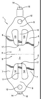
A carrier comprising an elongated flexible portion comprising a base having
first and second
sides, a first pair of arms extending from the first side of the base, a
second pair of arms
extending from the second side of the base, the first pair of arms being
joined to a first end
portion having a central area, the second pair of arms being joined to a
second end portion
having a central area, a first strip portion having a first end and a second
end; the first end
being detachably connected to the first side of the base, and the second end
being
connected to the first end portion, a second strip portion having first and
second ends; the
first end being detachably connected to the second side of the base, and the
second end
being connected to the second end portion.


French Abstract

L'invention porte sur un support, qui comprend une partie souple allongée comprenant une base ayant des premier et second côtés, une première paire de bras s'étendant à partir du premier côté de la base, une seconde paire de bras s'étendant à partir du second côté de la base, la première paire de bras étant réunis à une première partie d'extrémité ayant une zone centrale, la seconde paire de bras étant réunis à une seconde partie d'extrémité ayant une zone centrale, une première partie de bande ayant une première extrémité et une seconde extrémité ; la première extrémité étant reliée de façon détachable au premier côté de la base, et la seconde extrémité étant reliée à la première partie d'extrémité, une seconde partie de bande ayant des première et seconde extrémités ; la première extrémité étant reliée de façon détachable au second côté de la base, et la seconde extrémité étant reliée à la seconde partie d'extrémité.

Claims

Note: Claims are shown in the official language in which they were submitted.


Claims

1. A carrier comprising:
an elongated flexible portion comprising a base having a first side and a
second side;
a first pair of arms extending from the first side of said base;
a second pair of arms extending from said second side of said base;
said first pair of arms being joined to a first end portion having a central
area;
said second pair of arms being joined to a second end portion having a central
area;
a first strip portion having a first end and a second end; said first end of
said first strip
portion being detachably connected to said first side of said base, and said
second end of said
first strip portion being connected to said first end portion;
a second strip portion having a first end and a second end; said first end of
said second
strip portion being detachably connected to said secon side of said base, and
said second end
of said second strip portion being connected to said second end portion.
2. The carrier according to claim 1, wherein a cut-out is present in said
first and second end
portions.
3. The carrier according to claims 1 or 2, wherein the first and second
strip portions are
integral with the carrier.
4. The carrier according to claim 1, 2 or 3, manufactured from a polymer.
5. The carrier according to claim 4, wherein the polymer is low density
polyethylene.
6. The carrier according to claim 4, wherein the polymer is high density
polyethylene.
7. The carrier according to any one of claims 1 to 6, wherein the carrier
is manufactured
from a single sheet of material.
8. The carrier according to any one of claims 1 to 7, wherein a tab having
an aperture
therein is detachably connected to said first and second end portions.

7

9. A carrier comprising:
means for supporting a box;
means for securing the box to the support means, said securing means
comprising a
plurality of strips having a first end and a second end, said first end of
each of said strips being
detachable from the support means such that the detached first ends of said
strips can be
secured together to retain the box within the carrier.
10. A method of securing a box within a carrier, comprising,
providing a means for supporting the box;
providing a means for securing the box to the support means, said securing
means
comprising a plurality of strips having a first end and a second end
detaching said first end of each of said strips from the support means;
securing said detached first ends of said strips together to secure the box
within the
carrier.
11. A carrier comprising: an elongated flexible portion comprising a base
having a first side
and a second side; a first pair of arms extending from the first side of said
base; a second pair
of arms extending from said second side of said base; said first pair of arms
being joined to a
first end portion having a central area; said second pair of arms being joined
to a second end
portion having a central area; a first strip portion having a first end and a
second end; said first
end of said first strip portion being detachably connected to said first side
of said base, and said
second end of said first strip portion being permanently connected to said
first end portion; a
second strip portion having a first end and a second end; said first end of
said second strip
portion being detachably connected to said second side of said base, and said
second end of
said second strip portion being permanently connected to said second end
portion wherein said
first ends of the first and second strip portions when detached form free ends
of said strip
portions;
wherein said first side of said base, said first pair of arms, said first end
portion, and said
first strip portion define a first pair of apertures on said first side of
said carrier; and
wherein said second side of said base, said second pair of arms, said second
end
portion, and said second strip portion define a second pair of apertures on
said second side of
said carrier;
8

wherein the first and second pair of apertures are dimensioned to receive
corner portions
of a box; and
wherein said first end of said first strip portion and said first end of said
second strip
portion are adapted to be secured together to retain a box within the carrier.
12. The carrier according to claim 11, wherein a cut-out is present in said
first and second
end portions.
13. The carrier according to claims 11 or 12, wherein the first and second
strip portions are
integral with the carrier.
14. The carrier according to claim 11, 12 or 13, manufactured from a
polymer.
15. The carrier according to claim 14, wherein the polymer is low density
polyethylene.
16. The carrier according to claim 14, wherein the polymer is high density
polyethylene.
17. The carrier according to any one of claims 11 to 16, wherein the
carrier is manufactured
from a single sheet of material.
18. The carrier according to any one of claims 11 to 17, wherein a tab
having an aperture
therein is detachably connected to said first and second end portions.
19. A carrier comprising: means for supporting a box; means for securing
the box to the
support means, said securing means comprising a plurality of strips having a
first end and a
second end, said first end of each of said strips being detachable from the
support means to
form free ends, wherein said free ends of said strips can be secured together
to retain the box
within the carrier.
20. A method of securing a box within a carrier as set forth in claim 1,
comprising, providing
a means for supporting the box; providing a means for securing the box to the
support means,
said securing means comprising a plurality of strips each having a first end
and a second end
9


detaching said first end of each of said strips from the support means;
securing said detached
first ends of said strips together to secure the box within the carrier.
21.
The carrier according to any one of claims 11 to 18, wherein said first and
second pair
of apertures are asymmetrical.


Description

Note: Descriptions are shown in the official language in which they were submitted.


CA 02768294 2012-01-16
WO 2011/008228
PCT/US2010/000900
CARRIER FOR A BOX
TECHNICAL FIELD
[0001] The invention is directed to a carrier for a box, and the like,
which
allows the box, or a plurality of boxes, to be secured within the carrier and
transported in a horizontal position within the carrier. The invention is also

directed to a method for securing and carrying a box, or the like, using the
carrier.
BACKGROUND OF THE INVENTION
[0002] Typically, square or rectangular boxes are used for carrying food
items, such as pizza, for which it is necessary to secure and carry the box in
a
substantially horizontal position while transporting the box containing the
food
item. Conventional grocery carriers are not useful for this purpose, since the

bags are of insufficient size, and the opening of the bag too narrow, to
accommodate a pizza box.
[0003] Prior art carriers for boxes have thus been adapted by providing cut-

out portions in the carrier to accommodate the four corners of the box,
typically
for boxes which are required to be carried in one particular orientation to
prevent
the contents of the box from spilling out, or to prevent the contents from
moving
around inside the box.
[0004] One of the shortcomings of the prior art carriers, however, is that
the
boxes are usually insufficiently secured within the carrier, so that the boxes
can

CA 02768294 2012-01-16
WO 2011/008228
PCT/US2010/000900
easily fall out of the container, especially if one of the carrying handles is

accidentally released by the user.
[0005] It is therefore a primary object of the present invention to provide
a
box carrier which would keep the box or boxes held in the carrier in a secure
position.
[0006] It is a further objection of the present invention to provide a box
carrier which would prevent the box or boxes from falling out of the carrier
if one
of the handles of the carrier is accidentally let go by the user.
SUMMARY OF THE INVENTION
[0007] These problems and others are addressed by the present invention
which comprises a flexible carrier comprising a pair of detachable strips
which,
when detached at one of their ends from the carrier body, form a means of
securing a container within the carrier when the detached ends of the strips
are
secured together, for example, by means of a knot. Once the item(s) are
secured within the carrier, it will be appreciated that the item will not fall
from the
carrier even if one of the handles of the carrier slips from the user's grasp.
BRIEF DESCRIPTION OF THE DRAWINGS
[0008] These and other objects of the present invention will be appreciated
and understood by those skilled in the art from the detailed description of
the
preferred embodiments of the invention and the following drawings of which:
2

CA 02768294 2013-10-29
[0009] FIG. 1 is a line drawing of the carrier according to the present
invention in an open,
unfolded configuration.
[0010] FIG. 2 is a line drawing showing the carrier according to the present
invention in a folded,
two-layer configuration.
[0011] FIG. 3 is a line drawing showing a user gripping the carrier in
connection with transporting
items secured within the carrier by the tied strip portions.
[0012] FIG. 4 is a line drawing showing a user accidentally letting go of one
handle of the carrier
and the pizza box remaining secured in the carrier by the tied strip portions.
DETAILED DESCRIPTION OF THE INVENTION
[0013] With reference to the FIGS. 1 and 2, it can be seen that the carrier 1
comprises an
elongated flexible portion 2 comprising a base 3 having a first side 4 and a
second side 5; a first
pair of arms 6 extending from the first side 4 of said base 3; a second pair
of arms 7 extending
from said second side 5 of said base 3; said first pair of arms 6 being joined
to a first end portion
8; said second pair of arms 7 being joined to a second end portion 9; a first
strip portion 10
having a first end and a second end; said first end of said first strip
portion 10 being detachably
connected to said first side 4 of said base 3, and said second end of said
first strip portion 10
being connected at detachable connection 17 to said first end portion 8; a
second strip portion
11 having a first end and a second end; said first end of said second strip
portion 11 being
detachably connected at detachable connection 17 to said second side 5 of said
base, and said
second end of said second strip portion 11 being connected to said second end
portion 9.
[0014] A cut-out 12 is present in said first 8 and second 9 end portions, the
end portions 8, 9
with cut-outs serving as carrying handles. When the two halves of the carrier
are brought
together, the user places his or her fingers through the two cut-outs to grip
the carrier in a closed
configuration.
3

CA 02768294 2013-10-29
,
[0015] A tab 13 having an aperture 14 therein may be detachably connected to
said first 8 and
second end 9 portions. The tab 13 and aperture 14 combination may be used to
hang the carrier
from a hook or similar device, and the carrier 1 detached from the tab 13 for
use.
[0016] On one half of the carrier, the base 3, pair of arms 6, end portion 8,
and strip 10 define
a pair of cut-outs 15 when the first end of strip portion 10 is detachably
connected at detachable
connection 17 to the first side 4 of base 3. On the other half of the carrier,
the base 3, pair of
arms 7, end portion 9, and strip 11 define a pair of cutouts 16 when the first
end of the strip 11
is detachably connected at detachable connection 17 to the second side 5 of
base 3.
[0017] To secure a box 19 within the carrier 1 , the box 19 is first placed on
the carrier 1 with the
carrier 1 in the unfolded configuration, with opposing corners of the box 19
pointing towards
opposing end portions 8, 9. Then the first end of strip portions 10, 11 are
detached from base
3 at detachable connection 17 and secured together by any suitable means,
preferably by tying
the detached first ends of the strip portions 10, 11 together in a knot 18 .
The carrier 1 with
box(es) 19 secured therein can then be picked up by the user by means of the
cut-outs 12
4

CA 02768294 2012-01-16
WO 2011/008228
PCT/US2010/000900
and the carrier transported (FIG. 3). If the user accidentally lets one handle
of
the carrier slip from their grasp, the box 19 will remain secured in the
carrier 1 by
the knot 18 securing the strip portions 10, 11 (FIG. 4).
[0018] For transporting a single or a plurality of boxes of various sizes
and
various shapes in a horizontal position. More particularly, the device may be
used to transport boxes containing baked goods, including pizza, floral
arrangements, cartons of beverages, and the like.
[0019] The carrier may be used for transporting a single or a plurality
of
boxes of various sizes and various shapes in a horizontal position. More
particularly, the carrier may be used to transport boxes containing baked
goods,
including pizza, floral arrangements, cartons of beverages, and the like.
[0020] The carriers may be made of any flexible, deformable, material,
. including fabrics, including cotton, Nylon, and other polymers.
Preferably, the
carriers are manufactured from standard materials used to make traditional
carrier bags for transporting grocery items, including plastic of the Low
Density
Polyethylene (LDPE) or High Density Polyethylene (HDPE) type. The carriers
may also be manufactured from biodegradable polythene.
[0021] The carrier may be of different colors and textures, and have
printed
material thereon.
[0022] The carrier may be cut from a single layer sheet of material and
then
folded about its midpoint to form the carrier. In this way, the strips are
integrally
formed with the rest of the carrier. In a preferred embodiment, the carrier is
cut

CA 02768294 2012-01-16
WO 2011/008228
PCT/US2010/000900
from a double layer sheet so that the carrier is ready for use after being cut

without the need for folding.
[0023] The carrier may be dimensioned to accommodate boxes or articles of
different sizes.
[0024] While preferred embodiments of the invention have been shown and
described, various modifications and substitutions may be made thereto without

departing from the spirit and scope of the invention. Accordingly, it is to be

understood that the present invention has been described by way of
illustration
only, and this description should not be construed as limiting to the several
claims appended hereto.
6

Representative Drawing
A single figure which represents the drawing illustrating the invention.
Administrative Status

For a clearer understanding of the status of the application/patent presented on this page, the site Disclaimer , as well as the definitions for Patent , Administrative Status , Maintenance Fee  and Payment History  should be consulted.

Administrative Status

Title Date
Forecasted Issue Date 2014-07-29
(86) PCT Filing Date 2010-03-25
(87) PCT Publication Date 2011-01-20
(85) National Entry 2012-01-16
Examination Requested 2012-01-16
(45) Issued 2014-07-29

Abandonment History

Abandonment Date Reason Reinstatement Date
2014-03-25 FAILURE TO PAY APPLICATION MAINTENANCE FEE 2014-04-11

Maintenance Fee

Last Payment of $263.14 was received on 2023-12-07


 Upcoming maintenance fee amounts

Description Date Amount
Next Payment if small entity fee 2025-03-25 $253.00
Next Payment if standard fee 2025-03-25 $624.00

Note : If the full payment has not been received on or before the date indicated, a further fee may be required which may be one of the following

  • the reinstatement fee;
  • the late payment fee; or
  • additional fee to reverse deemed expiry.

Patent fees are adjusted on the 1st of January every year. The amounts above are the current amounts if received by December 31 of the current year.
Please refer to the CIPO Patent Fees web page to see all current fee amounts.

Payment History

Fee Type Anniversary Year Due Date Amount Paid Paid Date
Request for Examination $800.00 2012-01-16
Application Fee $400.00 2012-01-16
Maintenance Fee - Application - New Act 2 2012-03-26 $100.00 2012-03-15
Maintenance Fee - Application - New Act 3 2013-03-25 $100.00 2013-01-23
Reinstatement: Failure to Pay Application Maintenance Fees $200.00 2014-04-11
Maintenance Fee - Application - New Act 4 2014-03-25 $100.00 2014-04-11
Final Fee $300.00 2014-05-13
Maintenance Fee - Patent - New Act 5 2015-03-25 $200.00 2015-03-04
Maintenance Fee - Patent - New Act 6 2016-03-29 $200.00 2016-03-02
Maintenance Fee - Patent - New Act 7 2017-03-27 $200.00 2017-03-02
Maintenance Fee - Patent - New Act 8 2018-03-26 $200.00 2018-03-01
Maintenance Fee - Patent - New Act 9 2019-03-25 $200.00 2019-02-27
Maintenance Fee - Patent - New Act 10 2020-03-25 $250.00 2020-03-04
Maintenance Fee - Patent - New Act 11 2021-03-25 $255.00 2021-03-03
Maintenance Fee - Patent - New Act 12 2022-03-25 $254.49 2022-02-09
Maintenance Fee - Patent - New Act 13 2023-03-27 $254.49 2022-12-14
Maintenance Fee - Patent - New Act 14 2024-03-25 $263.14 2023-12-07
Owners on Record

Note: Records showing the ownership history in alphabetical order.

Current Owners on Record
GLOPACK, INC.
Past Owners on Record
None
Past Owners that do not appear in the "Owners on Record" listing will appear in other documentation within the application.
Documents

To view selected files, please enter reCAPTCHA code :


To view images, click a link in the Document Description column. To download the documents, select one or more checkboxes in the first column and then click the "Download Selected in PDF format (Zip Archive)" or the "Download Selected as Single PDF" button.

List of published and non-published patent-specific documents on the CPD .

If you have any difficulty accessing content, you can call the Client Service Centre at 1-866-997-1936 or send them an e-mail at CIPO Client Service Centre.


Document
Description 
Date
(yyyy-mm-dd) 
Number of pages   Size of Image (KB) 
Abstract 2012-01-16 1 17
Claims 2012-01-16 2 55
Drawings 2012-01-16 3 57
Description 2012-01-16 6 178
Abstract 2013-12-11 1 17
Representative Drawing 2012-03-21 1 5
Cover Page 2012-03-21 2 40
Claims 2013-11-05 4 126
Description 2013-10-29 6 179
Claims 2013-10-29 4 126
Representative Drawing 2014-07-09 1 6
Cover Page 2014-07-09 2 41
PCT 2012-01-16 8 376
Assignment 2012-01-16 3 96
Fees 2012-03-15 1 44
Prosecution-Amendment 2013-04-29 2 48
Fees 2013-01-23 1 44
Prosecution-Amendment 2013-11-05 3 81
Prosecution-Amendment 2013-10-29 10 348
Fees 2014-04-11 1 46
Correspondence 2014-05-13 2 47