Note: Descriptions are shown in the official language in which they were submitted.
CA 02768474 2012-01-17
WO 2011/009071 PCT/US2010/042321
CATALYST AND METHODS FOR PRODUCING
MULTI-WALL CARBON NANOTUBES
Background of the Invention
[001] The present application claims priority to U.S. Provisional Application
Ser. No.
61/226,438 filed on July 17, 2009. The entirety of U.S. Provisional
Application Ser. No.
61/226438 is incorporated herein by reference.
[002] Carbon nanotubes are known to exist in single wall and multi-wall
configurations. Each
configuration provides certain benefits. Single wall nanotubes are preferred
for electronic
applications due to the low occurrence of structural anomalies. However, multi-
wall nanotubes
are generally lower in cost and will provide satisfactory performance in
electronic applications if
the number of walls forming the nanotubes can be controlled. Unfortunately,
current methods
for producing multi-wall carbon nanotubes lack the ability to control the
resulting number of
walls in the structure in the resulting nanotubes. As a result, currently
produced multi-wall
carbon nanotubes generally range in diameter from about 3 to 35 nm and
comprise 3 to 40
concentric graphene layers, i.e. walls. The layers are coaxially arranged
cylinders of carbon
atoms having an interlayer distance of about 0.37 nm. This wide distribution
range in walls and
external diameter size limits the value of multi-wall nanotubes for electrical
conductivity
applications, thermal conductivity applications and mechanical reinforcement
applications.
[003] In contrast, multi-wall nanotubes, having a relatively narrow
distribution range of walls
and external diameters, will provide electrical conductivity characteristics
approaching those of
single wall nanotubes. Additionally, multi-wall nanotubes will provide such
improvement at a
lower cost. Further, multi-wall nanotubes batches having narrow distributions
of wall numbers
and external diameters will provide enhanced thermal conductivity and
mechanical strength
when compared to batches having wide distribution ranges.
[004] While one might consider simply isolating a narrow distribution of multi-
wall carbon
nanotubes from the wide distribution ranges presently manufactured, technology
does not exist
for carrying out this task. Thus, the currently available multi-wall nanotubes
are provided solely
in batches or lots having the undesirable wide distributions of walls and
external diameters.
[005] As discussed in detail below, the present invention provides batches of
multi-wall
nanotubes having narrow distribution ranges of walls and diameters. When
incorporated into
thermoplastics the narrow distribution range batches provide electrical
conductivity
characteristics which rival single wall nanotubes and are significantly
improved over currently
available batches of multi-wall nanotubes. The current invention further
provides catalysts and
CA 02768474 2012-01-17
WO 2011/009071 PCT/US2010/042321
methods for preparing batches of multi-wall carbon nanotubes having narrow
distribution ranges
of walls and external diameters.
Summary of the Current Invention
[006] In one embodiment, the present invention provides a catalyst precursor
comprising
alumina (A1203), magnesium oxide (MgO) and magnesium aluminate (MgAl2O4) as a
catalyst
support. The catalyst precursor further comprises metallic oxides of cobalt,
iron and
molybdenum. The preferred metallic oxides include, but are not necessarily
limited to, one or
more of the following mixed metal oxides: CoFe2O4, CoMoO4, CoXo04, Fe2(Mo04)3,
CoxFeyMoO4; where x and y represent the atomic ratios of Co and Fe relative to
Mo and x is
from about 1.6 to about 6.5 and y is from about 0.1 to about 10.5. Mixed metal
oxides having
two or more metal components are preferred, as single metal oxides produce
carbon fibers and
other forms of carbon.
[007] In another embodiment, the present invention provides a method for
preparing a catalyst
precursor and a catalyst. The method involves initially preparing a solution
of mixed metallic
compounds comprising two or more of the following: a cobalt compound selected
from the
group consisting of cobalt acetate, cobalt nitrate; an iron compound selected
from the group
consisting of iron acetate, iron nitrate; a molybdenum compound selected from
the group
consisting of ammonium heptamolybdate and ammonium dimolybdate; and magnesium
nitrate.
This solution is reacted with an excess of aluminum hydroxide powder and the
reaction products
subsequently formed into a paste. Formation of the paste causes the reaction
products to
agglomerate thereby yielding a particle size distribution between about 100
and 1400 microns.
The reaction products are subsequently dried, reduced in size and calcined to
yield a catalyst
precursor. The currently preferred catalyst precursor has a particle size
distribution ranging from
70 im to 150 tm. Conversion of the precursor to a catalyst entails placing the
catalyst precursor
within a reaction chamber suitable for use as a fluidized bed reactor. The
catalyst precursor is
fluidized and pre-heated to the desired reaction temperature by passing an
inert gas selected from
the group consisting of nitrogen, argon or helium through the reaction
chamber. Upon achieving
steady state conditions at the desired reaction temperature, the inert gas is
replaced with a blend
of ethylene and inert gas. The catalyst precursor converts to the desired
catalyst during the first
five minutes of contact with the blend of ethylene and inert gas. During the
conversion process,
cobalt and iron oxides are reduced to the respective metals. Additionally, a
portion of the iron
oxide is reduced to iron carbide (Fe3C) and the molybdenum oxides are reduced
to molybdenum
carbide (Mo2C).
2
CA 02768474 2012-01-17
WO 2011/009071 PCT/US2010/042321
[008] Still further, the present invention provides a method of producing
multi-wall carbon
nanotubes wherein the resulting batch of multi-wall nanotubes has a narrow
distribution as to the
number of walls making up the nanotubes and a narrow distribution of external
diameters for the
resulting nanotubes. In the method of the current invention, the catalyst
precursor is prepared as
discussed above. Following conversion of the catalyst precursor to the reduced
metal catalyst,
flow of the ethylene/inert gas continues under the desired reaction conditions
for a period of time
sufficient to yield multi-wall carbon nanotubes. The ethylene/inert gas
contains from about 10%
to about 80% ethylene by volume and flows at a rate sufficient to fluidize the
bed of catalyst
particles. Following a reaction period of about 10 to about 30 minutes, the
flow of gas to the
reaction chamber is cut off and the particles carrying the multi-wall
nanotubes are removed.
About 95% to about 98% of the resulting carbon product carried by the spent
catalyst is carbon
nanotubes. From about 60% to about 90% of the resulting batch of multi-wall
carbon nanotubes
have from 3 to 6 walls and external diameters ranging from about 3 nm to about
7 rim. Thus, the
present invention also provides a novel product comprising carbon nanotubes
having 3 to 6 walls
and external diameters ranging from about 3 nm to about 7 nm,
Brief Description of the Figures
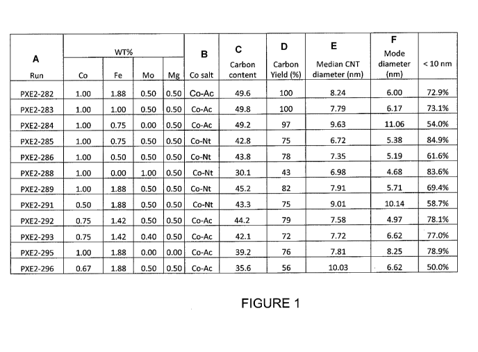
[009] FIGURE 1 provides a tabular representation of the carbon yield and
carbon nanotube
diameter profile for various catalyst compositions on an alumina support.
[010] FIGURE 2A provides graphical representations of the carbon nanotube
diameter
distribution for the catalytic composition corresponding to PXE2-282 in Figure
1.
[011] FIGURE 2B provides graphical representations of the carbon nanotube
diameter
distribution for the catalytic composition corresponding to PXE2-285 in Figure
1.
[012] FIGURE 2C provides graphical representations of the carbon nanotube
diameter
distribution for the catalytic composition corresponding to PXE2-288 in Figure
1.
[013] FIGURE 2D provides graphical representations of the carbon nanotube
diameter
distribution for the catalytic composition corresponding to PXE2-295 in Figure
1.
[014] FIGURE 3 is a tabular representation of the effect of reaction
temperature and gas
composition on the carbon yield and selectivity to smaller diameter tubes.
[015] FIGURE 4A depicts the carbon nanotube diameter distribution as
determined by TEM
corresponding to the SMW- 100 carbon nanotube product.
[016] FIGURE 4B depicts the carbon nanotube diameter distribution as
determined by TEM
corresponding to the MWCNT A carbon nanotube product.
3
CA 02768474 2012-01-17
WO 2011/009071 PCT/US2010/042321
[017] FIGURE 4C depicts the carbon nanotube diameter distribution as
determined by TEM
corresponding to the MWCNT B carbon nanotube product.
[018] FIGURE 4D depicts the carbon nanotube diameter distribution as
determined by TEM
corresponding to the MWCNT C carbon nanotube product.
[019] FIGURE 5 is a graphical representation of electrical volume resistivity
for SMW-100
carbon nanotubes and three commercial carbon nanotube products in
polycarbonate.
[020] FIGURE 6A is a graphical representation of surface resistance on the
front and back of
composites containing Nylon66 resin loaded with 2.5wt% SMW-100 carbon
nanotubes or loaded
with 2.5 wt% of commercially available multi-wall carbon nanotubes.
[021] FIGURE 6B is a graphical representation of surface resistance on the
front and back of
composites containing Nylon66 resin loaded with 3.5wt% SMW- 100 carbon
nanotubes or loaded
with 3.5 wt% of commercially available multi-wall carbon nanotubes.
[022] FIGURE 7 depicts surface resistivity of thin film comprising different
forms of carbon
nanotubes.
Detailed Description of the Preferred Embodiments
[023] The following detailed disclosure of the current invention will describe
the catalyst
precursor, methods of preparing the catalyst precursor and conversion thereof
to the desired
catalyst. Additionally, the present invention provides methods of producing
batches of desired
multi-wall carbon nanotubes on the catalyst wherein the carbon nanotube
product has a narrow
range distribution of walls and external diameters. As used herein, "carbon
content" refers
the percentage of the final product (carbon nanotube + catalyst) that is
carbon-based. So if 250
g of the final product is carbon and the final product is a total of 500 g,
then carbon content is
50% or 50.0 (as used in figure 1). As used herein, "carbon yield" refers to
the amount of carbon
product produced relative to the amount of catalyst used in the reaction. It
is defined by the
following equation: (amount of carbon in final product (g)/amount of catalyst
(g)) X 100. For
example, a reaction that yields 250 g carbon product where 250 g of catalyst
was used in the
reaction would have a carbon yield of 100% ((250g/250g) X 100 = 100%). As used
herein,
(including Figures 2A-2D; 2A-4D), "frequency" refers to the number of carbon
nanotubes in a
sample having a specified diameter (x axis). For example, in figure 2A, there
are approximately
20 carbon nanotubes that have a diameter of about 6 nm.
1. The Catalyst Precursor and Catalyst
[024] The catalyst precursor of the present invention has a surface phase of
mixed metal oxides
supported on a particle of alumina and magnesium aluminate. A mixed metal
oxide is an oxide
4
CA 02768474 2012-01-17
WO 2011/009071 PCT/US2010/042321
having two or more metal components. Additionally, the support of
alumina/magnesium
aluminate carries a surface treatment of magnesium oxide. The magnesium oxide
carried by the
alumina/magnesium aluminate particle is not necessarily an encompassing layer.
The atomic
ratio of MgO to A1203 is between about 0.02 and 0.04. Stated in other terms,
for a ratio of
0.02:1, for every atom of MgO there are 50 atoms of A1203 while at a ratio of
0.04:1, for every
atom of MgO there are 25 atoms of AI203. As noted below, a portion of the MgO
used in these
calculations will be converted to MgA12O4.
[025] The preferred surface phase of mixed metal oxides includes but is not
limited to, one or
more of the following: CoFe204, CoMo04s CoXMoO4, Co,,FeyMo04, Fe2(Mo04)3.
Typically, the
metal oxides provide the following percent by weight concentrations of metals
on the catalyst
precursor: Co from about 0.5% to about 2.0%; Mo from about 0.3% to about 2.0%;
and, Fe from
about 0% to about 3,0%. Thus, for Co,,FeyMo04, x may range from about 1.6 to
6.5 and y may
range from 0.1 to 10.5. More preferably, x will be about 3.3 and y will range
from 2.6 to 6.3. In
any event, a sufficient amount of the metal oxides are present on the catalyst
precursor such that
the resulting catalyst comprises the following percent by weights of the metal
component: Co
from about 0.5% to about 2.0%; Mo from about 0.3% to about 2.0%; and, Fe from
about 0% to
about 3.0%. In the resulting catalyst, the iron may be present as a reduced
metal or a carbide
(Fe3C), while the molybdenum is present as a carbide (Mo2C).
[0261 Preferably, the percent by weight of each metal component based on the
weight of the
catalyst precursor composition is: Co, from about 0.75% to about 1.5%; Mo,
from about 0.5% to
about 1.0%; and, Fe, from about 0.5% to about 2.0%. Accordingly, the active
metal components
are present in the following atomic ratios, wherein Mo is constant: the ratio
of Co to Mo ranges
from about 1.6 to about 6,5, more preferably from about 2.44 to about 4.88 and
most preferred
about 3.3; and the ratio of Fe to Mo from about 0 to about 10.5, more
preferably about 1.75 to
about 6.98 and most preferred about 2.62 to about 6.28.
[0271 The presence of Mg ions on the catalyst support reduces the number of
strong acid sites
on the surface of the Alumina support. By reducing the number of strong acid
sites on the
surface of the catalyst support, use of the improved catalyst will produce
primarily carbon
nanotubes and significantly less amorphous carbon or other carbon products. As
discussed
below, catalytic reactions using the improved catalyst produce at least 90%
and preferably
greater than 98% carbon nanotubes as the resulting carbon product.
[0281 The catalyst precursor of the present invention preferably has a
particle size between
about 20 m and about 500 m. Preferably, the particle size is between about
20 gm and 250
m. More preferably, the catalyst precursor has a particle size between about
20 m and about
CA 02768474 2012-01-17
WO 2011/009071 PCT/US2010/042321
150 Km. In the currently preferred method discuss below, the particles range
in size from about
70 gm to about 150 gm.
[0291 The catalyst precursor described above is converted to catalyst
particles by reduction of
the metal oxides to the respective metals and metal carbides, i.e. Fe , Fe3C,
Co' and Mo2C. The
catalyst particles have the same atomic ratios of metal present as the
catalyst precursor. The
resulting nano-sized deposits of metallic cobalt and metallic iron will
determine the interior
diameter of the multi-wall nanotubes produced on the catalyst particles.
Additionally, the
presence of the Mo2C, disperses or spaces the metallic cobalt, thereby
precluding sintering of the
cobalt and providing the desired cobalt particle size. In general, the
resulting metal deposits on
the support will have diameters ranging from about 1.5 urn to about 3.0 nm.
Preferably, the
resulting metal deposits of reduced iron and reduced cobalt will have
diameters ranging from
about 1.5 nm to about 2.2 nm. Additionally, as noted above, the final catalyst
particles have
fewer surface acid sites than catalyst particles utilizing only alumina as a
support.
[0301 In summary, the final catalyst particles of the present invention have
particle sizes
between about 20 gm and about 500 gm. Preferably, the particle size is between
about 20 gm
and 250 gm. More preferably, the catalyst precursor has a particle size
between about 20 gm
and about 150 gm. In the currently preferred method of making multi-wall
nanotubes discussed
below, the presently preferred particle size is about 70 gm to about 150 gm.
The catalyst
particles comprise:
a. gamma alumina (y-AI203) between about 91.0% and 97.6% by weight, preferably
between about 94.8% and about 97.3% by weight;
b. Mg (in the form of MgO and MgAl2O4) between about 0,5% and about 3.3% by
weight, preferably between 0.5% and 1.0%;
c. reduced Co from about 0.5% to about 2.0% by weight, preferably from about
0.75% to about 1.5% by weight;
d. Mo, in the form of Mo2C from about 0.3% to about 2.0% by weight, preferably
from about 0.5% to about 1.0% by weight; and,
e. Fe, in the form of reduced iron and iron carbide (Fe , Fe3C) from about 0%
to
about 3.0% by weight, preferably from about 0.5% to about 2.0% by weight.
Typically, less than 2.0% by weight of the catalyst particle will be metal
carbides. The atomic
ratios of the reduced metals for catalytic production of multi-wall carbon
nanotubes will not vary
substantially from the catalyst precursor as the metal carbides are not
produced in substantial
quantities.
6
CA 02768474 2012-01-17
WO 2011/009071 PCT/US2010/042321
2. Method of Preparing the Catalyst Precursor Particles and Catalyst Particles
[031] The current invention provides methods for manufacturing a catalyst
precursor and a
catalyst suitable for the catalytic formation of multi-wall carbon nanotubes.
In particular, the
catalyst of the current invention enables the production of batches of multi-
wall carbon
nanotubes having a narrow distribution range of walls and diameters.
[032] In a preferred embodiment, the method initially involves preparing a
solution of mixed
metallic compounds comprising two or more of the following: a cobalt compound
selected from
the group consisting of cobalt acetate, cobalt nitrate; an iron compound
selected from the group
consisting of iron acetate, iron nitrate; a molybdenum compound selected from
the group
consisting of ammonium heptamolybdate and ammonium dimolybdate; and magnesium
nitrate.
The preferred solution comprises cobalt acetate, iron nitrate, ammonium
heptamolybdate and
magnesium nitrate in water.
[033] Regardless of the cobalt compound chosen, the solution contains a
concentration. of
cobalt ion between about 20 g/L and about 50 g/L; a concentration of
molybdenum ion between
about 10.5 gIL and about 70.3 g/L; a concentration of iron ion between about
35 gIL and about
105 g/L; and, a concentration of Mg ion between about 6.7 g/L to about 27.0
g/L. The preferred
solution contains between about 26.7 g/L and about 40.0 g/L cobalt ion;
between about 17.6 g/L
and about 35.2 g/L molybdenum ion; between about 52.7 g/L and about 70.1 g/L
iron ion; and,
between about 6.7 gIL and about 13.5 g/L magnesium ion. Most preferred is a
solution of about
33.4 g/L cobalt ion; of about 17.6 g/L molybdenum ion; of about 63.1 g/L iron
ion; and, about
6.7 gIL magnesium ion, Proper selection of the metal ion concentration will
enhance the
formation of the desired mixed metal oxides. Thus, it is desirable to provide
the proper
stoichiometric ratios of the metals in solution to achieve this result.
[034] The above referenced metal ions are then reacted with aluminum hydroxide
to yield a
mixture of metal hydroxides and other ionic compounds including, but not
limited to, the
following hydroxides where the stoichiometric ratios may be varied from that
shown: Mg(OH)2,
Fe(OH)3, Co(OH)2, CoMoO4=nH2O, Fe2(MO04)3'nH2O. Typically the foregoing
reaction takes
place at room temperature over a period of about two to four hours. The
reaction products have
a paste like consistency which promotes agglomeration of the particles.
Preferably, the paste has
a moisture content of about 20% to about 40% water by weight, More preferably,
the paste
contains from about 25% to about 30% water by weight.
[035] If necessary for agglomeration of the particles, the paste-like product
is manipulated to
yield agglomerated particles having particle sizes ranging from about 100 tm
to about 1400 m.
Typically, the particles will agglomerate during the reaction. Preferably, the
agglomerated
7
CA 02768474 2012-01-17
WO 2011/009071 PCT/US2010/042321
particles are between about 100 m to about 500 m. In the preferred process,
the agglomerated
particles are mixed in a machine which kneads or mixes the paste for about 20
to about 50
minutes. Following the kneading, the product is allowed to age for about 2 to
3 additional hours.
The total time period will depend upon the batch size. For batches of about
200 to about 2000
grams, the preferred kneading period will be about 30 minutes. Larger batches
will require
longer mixing times. Following agglomeration, the particles are dried and
sieved to isolate
particles less than 1400 m. Preferably, the sieving step provides particles
in the range of about
100 m to about 500 m.
[036] The agglomerated particles are dried to a moisture content of about 10%
to about 20%
water by weight. Preferably, the dried particles have less than 15% water by
weight. The
drying step preferably takes place at a temperature between about 30 C and 50
C.
[037] Following drying and sieving, the particles are calcined under a flowing
gas at a
temperature between about 400 C to about 600 C for a period of about 3 hours
to about 8 hours.
More preferably, the calcining step takes place at a temperature between about
400 C and 500 C
for a period of about 3.5 hours to about 4.5 hours. Most preferably, the
calcining step occurs at a
temperature of about 440 C to about 460 for a period of about 3.5 hours to
about 4.5 hours.
Preferably, the calcining gas is selected from air, nitrogen, helium and
mixtures thereof.
Typically, the preferred calcining gas is a gas that is inert under the
calcining conditions. The
drying and calcining steps reduce the agglomerated particles to a particle
size between about 20
m and 500 m. Alternatively, prior to calcining the particles are sieved and
if necessary ground
such that calcining will produce particles between 20gm and 250Rm. Preferably,
calcining
produces particles between about 20 m and 200 m. More preferred are
particles between
about 20 m and 150 m. In the preferred method discussed below, the preferred
particles range
in size from about 70 m to about 150 pm. The resulting particles are
essentially free of water
moisture, i.e. no greater than 3% moisture by weight.
[038] Calcining of the particles converts the metal hydroxides to the
respective oxides. For
example, calcining of iron hydroxide with molybdate yields iron-molybdate
(Fe2(Mo04)3).
Likewise, calcining cobalt hydroxide with molybdate yields cobalt-molybdate
(CoMoO4).
Further, during the calcining process Fe(OH)3 and Co(O11)2 combine to yield
CoFe204. Finally,
during calcining Mg(OH)2 yields MgO and the aluminum hydroxide (Al(OH)3)
converts to
gamma alumina, i.e. y-A1203. During the calcining process, the oxidation of
Mg(OH)2 also
precludes the formation of strong acid sites on the surface of the 7-A1203.
The resulting surface
configuration is believed to be a mixed oxide similar to Mg-AI-O. In any
event, the surface
8
CA 02768474 2012-01-17
WO 2011/009071 PCT/US2010/042321
acidity of the y-A1203 carrying the MgO is significantly lower than the
surface acidity of y-A1203
when calcined without Mg(OH)2 present.
[039] Further, during the calcining process, in addition to forming the
respective oxides of
magnesium and aluminum, a portion of the Mgg2 ions adjacent to the aluminum
hydroxide
produces a parallel reaction. In this reaction, the solubility of the
magnesium ion in the alumina
allows the magnesium to displace a portion of the aluminum oxide tetrahedral
structure near the
surface of the particle thereby producing magnesium aluminate (MgA12O4), a
compound with a
spinel like structure. The formation of magnesium aluminate is favored over
the formation of
CoA12O4 and FeA1O3. Thus, the favored reaction preserves the catalytic metals
for reduction and
conversion to catalyst sites on the surface of the resulting support particle.
In particular, the
reduced cobalt takes the form of nanoparticle size domains on the surface of
the resulting
support, the iron becomes reduced iron and iron carbide and the molybdenum
becomes
molybdenum carbide. The iron carbide and reduced iron disperse the cobalt on
the surface of the
catalyst support thereby controlling the inner diameter of the resulting
nanotubes.
[040] The resulting catalyst support has a configuration wherein magnesium
aluminate is
incorporated into the crystalline structure of the y-A1203 primarily in the
outer layer of the
particle. Additionally, the surface of the gamma alumina carries MgO. Without
being limited by
theory, the MgO on the surface is likely a mixed oxide with the alumina of the
particle, i.e. a
mixed oxide of Mg-Al-O. This configuration results from the reaction of the
magnesium ions
with the alumina during the calcining process. Finally, the preferred catalyst
support is
preferably free of CoAI2O4 and FeA103. If FeAIO3 is present then preferably,
the catalyst
support comprises less than 0.5 percent by weight FeA103. If CoA12O4 is
present then
preferably, the catalyst support comprises less than 0.5 percent by weight
CoA1204.
[041] The presence of magnesium on the surface of the catalyst support
particle reduces the
surface acidity of the catalyst precursor support particle and the resulting
catalyst support
particle. By reducing the number acid sites on the surface of the support
particle, the method of
the current invention improves the production of carbon nanotubes and reduces
the formation of
other carbon types during the subsequent production of multi-wall carbon
nanotubes.
Additionally, by blocking the formation of CoA12O4 and FeA1O3 the presence of
the magnesium
ion precludes the loss of catalytic metals.
[042] Following calcining and particle size reduction, the resulting catalyst
precursor particles
have a catalyst support of y-A12031 MgA12O4 with a surface treatment of MgO.
Additionally, the
surface of the catalyst support carries a mixed phase of the referenced metal
oxides. As noted
9
CA 02768474 2012-01-17
WO 2011/009071 PCT/US2010/042321
above the preferred mixed metal oxides include but are not necessarily limited
to: CoFe2O4,
CoMoO4, CoxMoO4, Fe2(Mo04)3, Co,,FCyMoO4 with Co.FeyMo04 being the most
preferred.
[043] The resulting catalyst precursor is placed within a reaction chamber,
Preferably, the
reaction chamber is designed to produce a fluidized bed of catalyst particles
when a flowing gas
passes through the chamber and the particles located therein. To finally
convert the catalyst
precursor to a catalyst, the precursor must be heated and reacted with a
carbon containing gas, In
the following method for producing multi-wall nanotubes, the preferred gaseous
carbon
compound is ethylene. The conversion of the catalyst precursor to catalyst
takes place at a
temperature between about 600 C and 700 C during the first ten minutes of
contact with the
gaseous carbon compound. During this time period, the metal oxides are reduced
to the
respective metals and metal carbide discussed above. Additionally, the
formation of the Fe3C
and Mo2C preclude sintering and agglomeration of the reduced cobalt and iron
on the surface of
the support. Thus, the resulting nanoparticles of reduced cobalt preferably
have diameters
between about 1.5 nm to about 3.5 nm. More preferably, the reduced cobalt
metal particles on
the surface of the catalyst support have diameters between about 1.5 urn and
2.2 nm. The
reduced iron particles will have similar sizes, i.e. from about 1.5 nm to
about 3.5 urn preferably
between about between about 1.5 nm and 2.2 nm.
[044] The resulting catalyst comprises a support of y-A1203/ MgAI2O4 with a
surface treatment
of MgO and nano size particles of Fe3C and Mo2C on the surface of the support.
The reduced
metallic cobalt may be carried by the y-A1203/ MgAl2O4 and may also be found
on the
molybdenum carbide (Mo2C) and iron carbide (Fe3C). Additionally, reduced iron
may be carried
by the y-A1203/ MgA12O4 and may also be found on the molybdenum carbide (Mo2C)
and iron
carbide (Fe3C).
[0451 As discussed above the resulting catalyst particles have particle sizes
between about 20
gm and about 500 gm. Preferably, the particle size is between about 20 m and
250 rn. More
preferably, the catalyst has a particle size between about 20 .m and about 150
hum. In the
currently preferred method of making multi-wall nanotubes, the presently
preferred particle size
is about 70 m to about 150 m.
[046] The catalyst particles comprise: gamma alumina (y-A1203) between about
91.0% and
97.6% by weight, preferably between about 94.8% and about 97.3% by weight; Mg
(in the form
of MgO and MgA12O4) between about 0.5% and about 3.3% by weight, preferably
between 0.5%
and 1.0%; reduced Co from about 0.5% to about 2.0% by weight, preferably from
about 0.75%
to about 1.5% by weight; Mo, in the form of Mo2C from about 0.3% to about 2.0%
by weight,
preferably from about 0.5% to about 1.0% by weight; and, Fe, in the form of
reduced iron and
CA 02768474 2012-01-17
WO 2011/009071 PCT/US2010/042321
iron carbide (Fe , Fe3C) from about 0% to about 3.0% by weight, preferably
from about 0.5% to
about 2.0% by weight. Typically, less than 2.0% by weight of the catalyst
particle will be metal
carbides. The atomic ratios of the reduced metals for catalytic production of
multi-wall carbon
nanotubes will not vary substantially from the catalyst precursor as the metal
carbides are not
produced in substantial quantities.
[047] In an alternative method for preparing the catalyst precursor, the
magnesium nitrate has
been omitted from the initial solution. In this method, magnesium hydroxide
powder is
combined with the aluminum hydroxide powder and reacted with the solution of
metallic
compounds comprising a cobalt compound selected from the group consisting of
cobalt acetate,
cobalt nitrate, an iron compound selected from the group consisting of iron
acetate, iron nitrate, a
molybdenum compound selected from the group consisting of ammonium
heptamolybdate and
ammonium dimolybdate and mixtures thereof. The preferred solution comprises
cobalt acetate,
iron nitrate, ammonium heptamolybdate and magnesium nitrate in water.
[048] Regardless of the cobalt compound chosen, the solution contains a
concentration of
cobalt between about 20 g/L and about 50 g/L; a concentration of molybdenum
ion between
about 10.5 gIL and about 70.3 g/L; a concentration of iron ion between about
35 g/L and about
105 g/L; and, a concentration of Mg ion between about 6.7 g/L to about 27.0
gIL. The preferred
solution contains between about 26.7 g/L and about 40.0 g/L cobalt ion;
between about 17.6 g/L
and about 35.2 g/L molybdenum ion; between about 52.7 g/L and about 70.1 g/L
iron ion; and,
between about 6.7 g/L and about 13.5 g/L magnesium ion. Most preferred is a
solution of about
33.4 g/L cobalt ion; of about 17.6 g/L molybdenum ion; and about 63.1 g/L iron
ion.
[049] The solution of metal ions is subsequently reacted with an excess of
aluminum hydroxide
powder having particles ranging in size from about 20 xm to about 150 pm and
magnesium
hydroxide powder having particles ranging in size from about 20 m to about
150 gm.
Following this reaction, the preparation of the catalyst precursor and the
subsequent catalyst is
identical to the process described above.
Manufacture of Multi-Wall Carbon Nanotube Batches Having Narrow Distribution
Ranges of
Walls and Diameters
[050] The following discussion concerning the catalytic production of multi-
wall carbon
nanotubes is essentially a continuation of the discussion above concerning the
preparation of the
catalyst precursor and the catalyst. Following placement of the calcined
catalyst precursors in
the reactor chamber, the particles are fluidized and converted to catalyst
particles. As noted
above, the catalyst may have particle sizes between about 20 m and about 500
m. Preferably,
the particle size is between about 20 gm and 250 gm. More preferably, the
catalyst precursor
11
CA 02768474 2012-01-17
WO 2011/009071 PCT/US2010/042321
has a particle size between about 20 m and about 150 m. In the currently
preferred method of
making multi-wall nanotubes, the presently preferred particle size is about 70
im to about 150
Rm, Thus, the particles are well suited for use in a fluidized bed reactor.
[0511 Following placement of the catalyst precursor particles in the reaction
chamber, a flowing
stream of nitrogen gas passes through the reaction chamber thereby fluidizing
the bed of
particles. The nitrogen gas is heated to a temperature sufficient to raise the
temperature within
the fluidized bed to a range of about 600 C to about 700 C. Alternatively, the
reaction chamber
may be located in a furnace or other suitable heating device. When located
within a furnace, the
reaction chamber will typically be heated by both the furnace and the gas.
More preferably, the
fluidized bed is pre-heated to a temperature between about 600 C to about 650
C. Most
preferably, the fluidized bed is pre-heated to about 610 C to about 630 C. One
skilled in the art
will recognize that other non-reactive gases such as argon or helium may be
substituted for
nitrogen. The primary requirement for the pre-heating step is fluidization and
heating of the
fluidized bed to the desired temperature without undesirable side reactions.
[0521 Upon stabilization of the temperature within the fluidized bed, the gas
flow to the bed is
switched from nitrogen to a reactive gas. The reactive gas is a non-reactive
carrier gas with a
carbon containing gas. The preferred carrier gas is nitrogen and the preferred
carbon containing
gas is ethylene; however, other carrier gases such as argon or helium will
perform equally well.
The preferred blend of ethylene in nitrogen by volume is between about 10% and
80% by
volume. More preferably, the reactive gas contains from about 20% to about 50%
by volume
ethylene in nitrogen, Most preferred is a reactive gas containing from about
20% to about 40%
by volume ethylene in nitrogen.
10531 The flow rate of the ethylene containing gas is not dependent upon the
size of the reaction
chamber. Rather, the volume of gas passing through the reaction chamber
depends upon the
grams of catalyst precursor within the reaction chamber. The flow rate will be
from about 70
L/min per kg of catalyst precursor to about 150 L/min per kg of catalyst
precursor. More
preferably, the flow rate will range between about 90 L/min per kg of catalyst
precursor to about
120 L/min per kg of catalyst precursor.
1054] The initial reaction of the ethylene containing gas with the catalytic
particles reduces the
metal oxides to their respective metals (Co' and Fe ) and metal carbides (M02C
and Fe3C). This
reduction step generally occurs over the first five minutes of the reaction
process. Preferably, the
reaction temperature is 600 C to 750 C. More preferably, the reaction
temperature is between
610 C and 650 C. Most preferably, the reaction temperature is 610 C.
Additionally, during the
first ten minutes of the reaction process, the ongoing reaction of ethylene
with the catalyst
12
CA 02768474 2012-01-17
WO 2011/009071 PCT/US2010/042321
precursor and subsequent catalyst particles is an exothermic reaction. Thus,
the preferred
method maintains the temperature of the fluidized bed below 670 C. Temperature
maintenance
may be achieved by lowering the temperature of the gas entering the reaction
chamber. If a
furnace is used, then the temperature of the furnace may also be reduced.
Preferably, the
temperature is maintained below 650 C as higher temperature will lead to an
increased
production of amorphous carbon. As the metal oxides are reduced, the ethylene
gas contacts the
resulting catalytic particles and begins to grow multi-wall carbon nanotubes.
Following the
reduction of metal oxides to catalytic particles, the reaction process
continues for about 10 to
about 40 minutes. More preferably, the reaction process following the
reduction of metal oxides
continues for about 15 to 25 minutes.
[055] The resulting carbon product carried by the now spent catalyst particles
is 98% free of
amorphous carbon and other carbon forms. Thus, 98% of the carbon product is
multi-wall
carbon nanotubes. Further, the resulting multi-wall carbon nanotubes primarily
have from 3 to 8
walls. More preferably, the resulting nanotubes carried by the spent catalyst
particles primarily
have from 3 to 6 walls and external diameters between about 4.0 nm to about
7.0 mn.
Preferably, at least 60% of the resulting multi-wall carbon nanotubes have
three to six walls and
external diameters between about 4.0 nm and about 7.0 nm. More preferable, the
method of the
current invention yields multi-wall carbon nanotubes wherein at least 75% of
the resulting multi-
wall carbon nanotubes having the desired narrow distribution range of 3 to 6
walls and diameters
between about 4.0 nm and 7.0 nm. More preferably, at least 85% of the
resulting nanotubes
carried by the spent catalyst have three to six walls and external diameters
between about 4.0 nm
and about 7.0 nm. Most preferably, with continuously maintained fluidization
of the catalyst
particles, the present invention will provide spent catalyst carrying multi-
wall carbon nanotubes
wherein 90% of the resulting multi-wall nanotubes will have 3 to 6 walls and
diameters between
about 4,0 nm and about 7.0 nm.
[056] The following examples and test data do not limit the nature of the
current invention.
Rather, this information will enhance the understanding of the current
invention.
EXAMPLE 1
Objective
[057] This example demonstrates the effect of various catalyst metal
compositions on carbon
yield and carbon nanotube diameter.
Methods
13
CA 02768474 2012-01-17
WO 2011/009071 PCT/US2010/042321
[0581 A variety of catalyst precursors were prepared to demonstrate the
importance of the
catalytic metals on the resulting multi-wall product. The table in Figure 1
identifies the nanotube
products produced for this comparison. For these examples, 600 grams of
catalyst precursor
prepared as discussed above, having particles sizes of 150 to 300 microns,
were placed in a
fluidized bed reactor. As discussed above, the method of the current invention
converts the
catalyst precursor to catalyst and subsequently grows multi-wall carbon
nanotubes on the
resulting catalyst. For each of the examples provided in Figure 1, the final
catalysts were reacted
at 610 C with 40% ethylene in nitrogen at a gas flow rate of 60 L/min (gas
flow/mass of catalyst
ratio of 100 L/min per Kg catalyst) for 20 minutes.
Results
[059] As depicted in Figure 1, the catalytic metal composition significantly
impacts the
resulting multi-wall nanotube product. For example, runs PXE2-282, PXE2-285,
PXE2-292 and
PXE2-293, provide data regarding multi-wall carbon nanotubes prepared with
catalyst precursors
having Co, Mo and from about 0.75 percent weight of iron to about 1.9 percent
weight of iron.
The resulting batch of nanotubes have a high yield of carbon nanotubes with a
median external
diameter from about 6.72 nm to about 8.24 nm and a mode external diameter from
about 4.97 rim
to about 6 nm. Between 75% and 85% of these carbon nanotubes have external
diameters of less
than 10 nm. Specifically, PXE2-282 represents a batch of multi-wall nanotubes
having a mode
diameter of 6.0 nm, the median diameter for the batch is 8.24 nm and 73% of
the batch had
diameters less than 10 mu. Similarly, PXE2-285 represents a batch of multi-
wall nanotubes
having a mode diameter of 5.38 nrn, the median diameter for the batch is, 6.72
nm and 85% of the
batch had diameters less than 10 nm. The values for PXE2-292 and PXE2-293 can
be easily
determined from Figure 1. As known to those skilled in the art, the term
"mode" when used in
this manner represents the value that occurs the most frequently in a data
set. Thus, for PXE2-
285, the most common diameter for nanotubes within the batch is 6.72 nm.
[060] These results demonstrate that catalyst precursor compositions
comprising Co from about
0.75 to about 1 percent weight of total metals of catalyst precursor, Fe from
about 0.75 to about
1.9 percent weight of total metals of catalyst precursor, and Mo from about
0.4 to 0.5 percent
weight of total metals of catalyst precursor, result in high percentage yields
of small diameter
carbon nanotubes.
[0611 In contrast, catalyst precursor particles lacking iron result in a
significant reduction in
carbon yield. For example, run PXE2-288 demonstrates a 57% loss in carbon
yield when iron is
removed from the precursor catalyst formulation. Interestingly, the resulting
product comprises
carbon nanotubes with a median external diameter of 6.98 and a mode external
diameter of 4.68.
14
CA 02768474 2012-01-17
WO 2011/009071 PCT/US2010/042321
This suggests that iron is not responsible for the small diameter of the
resulting carbon
nanotubes. However, the results seem to suggest that molybdenum plays a role
in limiting
carbon nanotube diameter. For example, run PXE2-284, produced carbon nanotubes
having a
median and mode external diameter of 9.63 nm and 11.06 nm, respectively.
Additionally, only
54% of the resulting carbon nanotubes had an external diameter less than 10 nm
compared to
85% in run PXE2-285, where Mo was used in the precursor composition, Figures
2A-2D further
illustrates the effect of removing either Fe or Mo from the catalyst precursor
on carbon nanotube
diameter distribution. Taken together, these results demonstrate that iron
acts to maintain carbon
yield while molybdenum promotes production of a smaller diameter carbon
nanotube.
EXAMPLE 2
Objective
[062] With reference to Figure 3, this example demonstrates the effect of
reaction temperature
and gas composition on carbon yield and carbon nanotube diameter.
Methods
[063] Catalyst compositions having the formulations of PXE2-282 and PXE2-285
in Figure 1
were used in this test as a reference. To determine the impact of reaction
temperature on the
resulting nanotube product, reactions were carried out at temperatures between
610-675 C.
Further, these tests determined the impact on the resulting nanotube product
due to changes in
ethylene concentration in the gas feed for variations of ethylene
concentration between 30-40 %.
Results
[064] Increasing the reaction temperature and/or lowering the gas composition
from 40% to
30% ethylene decreases the carbon yield and increases the diameter of the
carbon nanotubes.
Thus, in order to maximize carbon yield and to produce small diameter carbon
nanotubes, the
catalytic reaction should occur at about 610 C with a reactive gas mixture
containing 40%
ethylene.
EXAMPLE 3
Objective
[065] This example compares the electrical conductivity of composites
containing primarily
small diameter multi-wall carbon nanotubes having between 3-6 walls (diameters
of 4-8 nm) to
composites comprising larger diameter carbon nanotubes. This example and the
following
CA 02768474 2012-01-17
WO 2011/009071 PCT/US2010/042321
examples utilize the material prepared according to the current invention and
identified as PXE2-
282 in Figure 1 (referred to as SMW-100).
Methods
[066] Carbon nanotubes produced by the methods and catalyst compositions of
the current
invention (hereinafter, SMW-100 refers to multi-wall carbon nanotubes produced
by the catalyst
composition described for PXE2-282 in figure 1) were compared to various
commercially
available carbon nanotubes having diameter distributions described in Table 1
and Figures 4A-D.
The following Table 1 provides the carbon nanotube diameter distributions for
various
commercially available multi-wall carbon nanotubes and SMW-100. For example,
with regard
to SMW-100 ten percent of the nanotubes have diameters smaller than 4.2 nm,
50% of the total
nanotubes have diameters smaller than 6.7 nm and 90% of the total nanotubes
have diameters
smaller than 12 nm.
10% 50% 90%
SMW-100 .2 nm 6.7 nm 12.0 nm
MWCNT A 5.5 nm 7.8 nm 13.0 nm
CNT B 7.4 mn 12.0 nm 16.5 nm
MWCNT 7.1 nm 9.9nm 13.3 run
TABLE 1
[067] Polycarbonate Makrolon 2600 PC granules were melt mixed with the carbon
nanotube
sources described in Table 1. Melt mixing was performed in a DSM micro-
compounder (15
cm3) under the following conditions: screw speed - 200 rpm; temperature - 280
C; time - 5
min). Pressed plates (60 mm diameter x 0.5 mm thickness) were prepared from
extruded strands
(temperature: 280 C, time: 1 min, pressure: 100 kN). Carbon nanotube samples
were
characterized by TGA and TEM analysis (Figures 4A-D).
[068] Resistivity was measured with a Keithley 6517A Electrometer in
combination with a
Keithley 8009 test fixture (for resistivity > 107 Ohm cm) or a strip test
fixture (for resistivity <
107 Ohm cm). For the purposes of this disclosure, the term percolation
threshold is that
concentration of carbon loading at which there is one, and only one,
continuous conducting
pathway in the material.
16
CA 02768474 2012-01-17
WO 2011/009071 PCT/US2010/042321
Results
[069] Figure 5 demonstrates that the SMW-100 carbon nanotube material provides
the lowest
electrical percolation threshold. As depicted in Figure 5, a CNT loading of
0.33 wt.% satisfied
the requirement for electrical percolation. As shown by Figure 5, SMW-100
provided resistivity
reading of 104-102 Ohm/cm for loadings ranging from 0.5-1.0 wt%. In contrast,
the comparative
carbon nanotubes having diameters between 7-9 nm (MWNT A), 10-11 rim (MWNT C),
and 12-
15 nm (MWNT B) respectively yielded percolation thresholds of 0.50 wt%, 0.50
wt% and 0.55-
0.60 wt%.
[070] Based on the above, results, the use of a batch of straight multi-wall
carbon nanotubes
having the characteristics of SMW-100 provided by Table 1 and Figure 1 will
provide higher
conductivity properties at lower loading levels than other commercially
available sources of
multi-wall carbon nanotubes.
EXAMPLE 4
Objective
[071] This study compares the performance of composites based on commercially
available
multi-wall carbon nanotubes dispersed in Nylon 66 resin to composites prepared
from SMW-100
carbon nanotubes dispersed in Nylon66 resin.
Methods
[072] CNT-Nylon 6,6 compounding was performed via twin screw extrusion. The
resulting
composites were then injection-molded into standard ASTM test bars and plaque
(4in by 4in by
3.2mm). Conductivity measurements were then performed on the injection-molded
plaques
using a standard ProStat resistance meter as per ASTM D-257 for Volume and
Surface
resistance. Surface resistance was determined using PRF-912B probe at 25
predetermined
locations on each surface of the injection molded plaques - i.e. 25 points on
the front surface and
25 points on the back surface of the plaques. This rigorous testing is
designed to bring out any
minor variations in electrical performance due to non-uniformity in material
and/or processing.
The front surface of the plaques corresponds to where the ejector pins are
located. The back
surface of the plaques corresponds to the fixed part of the tool (closer to
Nozzle). Volume
resistances of the plaques were tested using a PRF-911 concentric ring at five
locations per
sample and averaged for both the front and back of the plaques.
Results
17
CA 02768474 2012-01-17
WO 2011/009071 PCT/US2010/042321
[073] The surface resistance data is depicted in Figures 6A and 6B. SMW-100
composites
exhibited lower and more uniform electrical resistance properties after
molding compared to the
commercially available multi-wall carbon nanotube (MWCNT). The surface
resistance, of the
MWCNT and SMW-100 filled samples are fairly uniform and consistent with very
good
agreement on the front and back surfaces of the plaques.
[074] Furthermore, Nylon 6,6 based composite with SMW-100 showed higher
conductivity
values than Nylon 6,6 based composite with commercially available grades of
MWCNT. The
SMW-100 composites also showed more uniform resistance values, with a narrower
range of
standard deviation between the tested points and between the front and back
surfaces of the
plaques. As reflected by Figures 6A and 6B, composites prepared from the
inventive carbon
nanotube material, i.e. a batch of nanotubes having a narrow distribution of
diameters and
number of walls, have improved conductivity when compared to currently
available materials.
EXAMPLE 5
Objective
[075] This example compares the surface resistivity of thin films containing
respectively:
SMW-100; single-wall carbon nanotubes (SWNT); double-wall carbon nanotubes
(DWNT); and,
commercially available multi-wall carbon nanotubes (MWCNT B - from Example 3).
Methods
[076] Carbon nanotube-based thin films having different degrees of
transparencies (80-95%
transmittance) were prepared using solutions containing 1 g carbon nanotube
/liter in 1% Triton-
X 100 surfactant. The solutions were then sonicated and centrifuged. The
various carbon
nanotube inks were deposited on a PET 505 substrate employing the rod coating
technique.
Results
[077] As depicted in Figure 7, films having 80-90 % transparency prepared with
SWNTs
demonstrate higher electrical conductivity than the other type of carbon
nanotube materials in
thin film. However, films prepared using the novel batch material of the
current invention, i.e.
the SMW-100, had better conductivity performance than films incorporating
conventional
DWNT and MWNT.
[078] Other embodiments of the current invention will be apparent to those
skilled in the art
from a consideration of this specification or practice of the invention
disclosed herein. Thus, the
foregoing specification is considered merely exemplary of the current
invention with the true
scope and spirit of the invention being defined by the following claims.
18