Note: Descriptions are shown in the official language in which they were submitted.
CA 02769217 2012-01-25
SP35911AP
1
OUTER SHELL SECTOR FOR A BLADED RING FOR AN AIRCRAFT
TURBOMACHINE STATOR, INCLUDING VIBRATION DAMPING SHIMS
DESCRIPTION
This invention generally relates to an
aircraft turbomachine, preferably of the turbojet or
turboprop type.
More particularly, the invention relates to
the compressor or turbine stator of such a
turbomachine, and more precisely to a bladed ring
sector comprising a plurality of stator blades and two
concentric shells supporting the blades and designed to
radially delimit a primary flow passing through the
turbomachine, inwards and outwards respectively. Such a
bladed ring is usually made using several sectors
arranged end to end, is usually used in the compressor
or the turbine as a guide vane or a nozzle.
Turbomachines usually comprise a low
pressure compressor, a high pressure compressor, a
combustion chamber, a high pressure turbine and a low
pressure turbine, in series. Compressors and turbines
comprise several rows of mobile blades at a
circumferential spacing, these rows being separated by
rows of fixed blades also at a circumferential spacing.
In modern turbomachines, high dynamic stresses are
applied to the guide vanes and nozzles. Technological
progress leads to a reduction in the number of stages
for equal or better performances, resulting in a higher
CA 02769217 2012-01-25
SP35911AP
2
load for each stage. Furthermore, changes to production
technologies have led to a reduction in the number of
parts, which reduces the damping effect of connections
between parts. This is the case particularly when an
abradable cartridge brazing technology is used which
eliminates a large source of dissipation of vibration
energy.
Document FR-A-2 902 843 discloses a means
of solving this vibration problem by breaking the outer
shell sector down into elementary sectors at a fixed
spacing from each other along the tangential direction
by the use of slits or radial cuts, oblique or in
another direction, each elementary sector supporting a
single blade of the bladed ring sector. Furthermore,
damping inserts in the form of strips are inserted
between the elementary sectors. The operating principle
is based on the introduction of a stiffness non-
linearity in the dynamic behaviour of the structure.
This non-linearity is triggered by a threshold
vibration level of the system. This vibration activity
causes a relative movement between the elementary
sectors of the blades and the damping inserts. This
relative movement causes successive loss and recovery
of adhesion of the damping inserts and consequently a
continuous variation of the local stiffness of the
system. Consequently, the mode(s) causing the vibration
activity are disorganised by the permanent variation of
the associated natural frequencies. Resonance of the
system cannot be set up because of the continuous
variation in the state of the dynamic system. This
reduces vibration amplitudes in the system.
CA 02769217 2012-01-25
SP35911AP
3
Nevertheless, even if this solution is
satisfactory in terms of reducing vibrations, it can be
improved. Furthermore, in this solution disclosed in
document FR-A-2 902 843, the damping inserts are held
in contact against the friction surfaces of the
elementary sectors due to the effect of the pressure
gradient between the aerodynamic flowpath and the
outside of the compressor, applying a radially inwards
force on these inserts. The disadvantage is that this
pressure gradient cannot be sufficient to
satisfactorily force the inserts into contact with the
friction surfaces. In this case, the result is firstly
a reduction in the vibration damping performances, but
also a possible loss of leak tightness of the air
flowpath.
Another disadvantage with this solution is
the fact that one of the blades in the bladed ring
sector will be overloaded. Aerodynamic forces applied
on the blades include a tangential component that
cannot be resisted in the outer shell sector, due to
its segmentation into tangentially spaced elementary
sectors. Thus, these tangential components are combined
and pass through the inner shell sector of the bladed
ring sector before passing through the blade located
adjacent to the anti-rotation stop fitted on the ring
sector. Therefore, this blade is very highly loaded due
to the incapability of the outer shell sector to
transmit static forces along the tangential direction.
Therefore, the purpose of the invention is
to at least partially overcome the problems mentioned
CA 02769217 2012-01-25
SP35911AP
4
Y
above that arise with embodiments according to prior
art.
The first purpose of the invention to
achieve this is an assembly forming an outer shell
sector for a bladed ring sector that will be used on a
compressor or turbine stator in an aircraft
turbomachine, said outer shell sector comprising
firstly a plurality of elementary sectors at a spacing
from each other along a tangential direction of said
assembly, and secondly vibration damping shims, each of
them being inserted between two elementary sectors
associated with it, placed directly consecutively along
said tangential direction.
According to the invention, the profile of
each vibration damping shim is approximately the same
as the profile of the elementary sectors.
Due to the particular profile of the shims,
the friction interface between the shims and the
elementary sectors is large which results in an
improved damping effect.
Furthermore, the fact that the shims are
forced into contact with the friction surfaces of the
elementary sectors can result in a perfect seal between
these elements, independent of the pressure difference
between the aerodynamic flowpath and the outside of the
compressor or the turbine. This seal is obtained by
construction, with shims applying forces on the
friction surfaces of the elementary sectors
approximately along the tangential direction. Note that
this seal is further reinforced during operation,
because the forces bringing the friction surfaces and
CA 02769217 2012-01-25
SP35911AP
the shims into contact with each other are accentuated
by application of the tangential component of
aerodynamic forces applied on the stator blades, on the
elementary sectors.
5 Concerning the tangential component of the
aerodynamic forces applied on the blades, note that one
of the essential advantages of this invention lies in
the fact that this component can transit through the
assembly forming an outer shell sector because the
outer shell sector is very much stiffened along the
tangential direction due to the particular positioning
of vibration damping shims, even though it is separated
into sectors along this direction. The result is that
there is no overload of the blades that are therefore
loaded approximately uniformly.
Finally, note that by adopting
approximately the same profile as the profile of the
elementary sectors, the outer radial delimitation of
the primary annular flow, also called the air flowpath,
is perfectly recreated between the elementary sectors
at a spacing from each other.
Preferably, said shim bears in contact with
two parallel plane friction surfaces facing each other
along said tangential direction and provided on said
two elementary sectors associated with said shim, and
said shim has two complementary plane friction surfaces
parallel to each other and cooperating with the two
corresponding friction surfaces of the elementary
sectors. The plane contacts between the friction
surfaces and the complementary friction surfaces give
satisfactory damping of vibrations by friction. It is
CA 02769217 2012-01-25
SP35911AP
6
also possible to make the two friction surfaces
simultaneously during a single machining operation, for
example by a single cutting operation, in order to
obtain straight slits, in other words slits in a
determined plane, inside which the corresponding shims
will subsequently be housed. This makes it very much
simpler to fabricate the assembly according to the
invention, which results in a significant cost and time
saving.
Preferably, said shim is provided with
hooks to hold it in place on the compressor or turbine
stator, therefore these hooks have the same profile as
the hooks fixed on the elementary sectors.
Preferably, the elementary sectors are
separated from each other by radial slits completely
filled in by said vibration damping shims.
Preferably, said vibration damping shims
extend approximately along an axial or oblique
direction of said assembly.
Another purpose of this invention applies
to a bladed ring sector designed to be installed on a
compressor or turbine stator of an aircraft
turbomachine comprising an assembly forming an outer
shell sector like that described above, an inner shell
sector and a plurality of blades at a tangential
spacing from each other and inserted between the
assembly forming the outer shell sector and the inner
shell sector. In this case, each elementary sector will
carry a single stator blade, or possibly several
blades, without going outside the scope of the
invention.
CA 02769217 2012-01-25
SP35911AP
7
r
The bladed ring may form a guide vane of a
compressor or a nozzle of a turbine.
Furthermore, the ring sector preferably
extends around an angular range of between 5 and 60 ,
but can be as much as 360 so as to form the entire
bladed ring.
Another purpose of the invention is an
aircraft turbomachine comprising a compressor or
turbine stator equipped with at least one bladed ring
sector like that described above.
Other advantages and characteristics of the
invention will appear in the detailed non-limitative
description given below.
This description will be made with
reference to the appended drawings among which;
- figure 1 shows a diagrammatic sectional
view of a turbomachine that will be equipped with one
or several bladed ring sectors according to this
invention;
- figure 2 shows a sectional view
representing part of the high pressure compressor of
the turbomachine shown in figure 1, and including a
bladed ring sector according to this invention;
figure 3 shows a perspective view of the
bladed ring sector shown in the previous figure, the
sector being in the form of a preferred embodiment of
this invention;
- figure 4 shows an axial view of part of
the bladed ring sector shown in the previous figure;
- figure 5 shows a profile view of the
shims and the elementary sectors of the bladed ring
CA 02769217 2012-01-25
SP35911AP
8
sector shown in the previous figures, along line V-V in
figure 4; and
- figures 6a to 6c show views
diagrammatically showing the different steps in a
fabrication process of the bladed ring sector shown in
the previous figures.
With reference firstly to figure 1, the
figure shows an aircraft turbojet 100 to which the
invention is applicable. It comprises, in order along
the upstream to downstream direction, a low pressure
compressor 2, a high pressure compressor 4, an annular
combustion chamber 6, a high pressure turbine 8 and a
low pressure turbine 10.
Figure 2 shows part of the high pressure
compressor 4. In a known manner, the compressor
comprises rows 14 of stator blades and rows 16 of rotor
blades alternating on an axial direction parallel to
the axis 12 of the compressor. The stator blades 18
distributed circumferentially/tangentially around the
axis 12, are included in a part of the stator called
the bladed ring 20, preferably constructed in sectors
along the circumferential direction 22. Thus, in the
following we will refer to a bladed ring sector 20, it
being understood that this sector 20 preferably extends
over an angular range of between 5 and 60 , but
possibly as much as 360 so as to form the entire
bladed ring.
The sector 20, therefore forming all or
part of a turbine nozzle or a compressor guide vane,
comprises an inner shell sector 24 forming the inner
surface radially delimiting a primary annular flow 26
CA 02769217 2012-01-25
SP35911AP
9
passing through the turbomachine, this shell sector 24
supporting the fixed roots of the stator blades 18. In
addition to these blades 18, the sector 20 also
comprises an assembly forming an outer shell sector 28
forming the outer surface radially delimiting the
primary annular flow, and supporting the fixed heads of
the blades 18.
In this respect, note that the sector 20
also comprises known additional elements fitted on the
shell sector 24, such as a radially internal abradable
coating 29 forming the annular sealing track contacted
by a sealing device 31 supported by the rotor stage 16
supporting the rotating blades and arranged on the
downstream side of the sector 20 concerned. The
rotating sealing device 31 is a known labyrinth or lip
seal type sealing device.
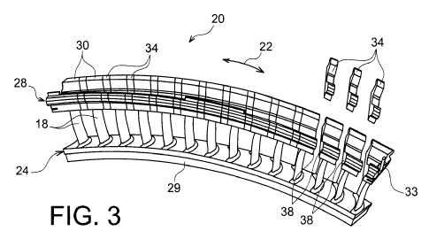
Figure 3 shows the bladed ring sector 20.
In the preferred embodiment described, the entire
turbine nozzle or compressor guide vane is obtained by
end to end placement of a plurality of these sectors
20, therefore each forming an angular or
circumferential portion of this bladed ring. The
angular sectors 20 (only one of which can be seen in
figure 3) are preferably deprived of any rigid direct
mechanical links connecting them to each other, their
adjacent ends being simply placed facing each other
with or without clearance.
More specifically with reference to figures
3 and 4, the figures show that the inner ring sector 24
is made in a single part and is not segmented. On the
other hand, the assembly 28 forming the outer shell
CA 02769217 2012-01-25
SP35911AP
sector 28 is segmented into elementary sectors 30 at a
spacing from each other along the tangential direction
22, by straight radial or slightly oblique slits 32,
therefore creating clearances between the directly
5 consecutive sectors 30. Each slit 32 is made along a
median straight line between two directly consecutive
blades 18, such that each elementary sector 30 supports
a single fixed stator blade 18. One of the two
elementary sectors 30 located at the ends of the sector
10 20 supports a rotation stop 33 projecting radially
outwards and that will cooperate with another part of
the compressor stator in a known manner.
The assembly 28 also comprises vibration
damping shims 34 housed between directly consecutive
elementary sectors 30.
More precisely, each vibration damping shim
34 is housed between two plane parallel friction
surfaces 38 facing each other along the tangential
direction 22, and provided on the corresponding
tangential ends facing each other on the two elementary
sectors associated with the shim. Similarly, each shim
34 has two complementary plane friction surfaces 40
parallel to each other and also parallel and in contact
with the two corresponding plane friction surfaces 38
with which they cooperate.
Therefore, each shim 34 is squeezed between
two directly consecutive elementary sectors 30, having
a shape complementary with the shape of the friction
surfaces 38.
The contact between the two friction
surfaces 38, 40 of each pair is preferably obtained as
CA 02769217 2012-01-25
SP35911AP
11
ti
soon as the shim 34 is put into position between its
two associated elementary sectors 30. The shims 34 thus
apply forces oriented approximately along the
tangential direction in contact with the friction
surfaces 38 of the elementary sectors, with their
complementary plane friction surfaces 40. These forces
are advantageously increased during operation by the
additional application of the tangential component of
aerodynamic forces applied on the stator blades, on the
elementary sectors.
As shown diagrammatically in figure 5, one
of the special features of this invention lies in the
fact that the profile of the shims 34 is approximately
the same as the profile of the elementary sectors, this
same profile corresponding to the profile of the outer
shell sector. In this disclosure, profile refers to the
global shape of the element seen along the tangential
direction 22, although a sectional view is shown in
figure 5.
Thus, the lower surface 46 of each shim 34,
like the elementary sectors 30, acts as the outer
radial delimitation of the air flowpath. Consequently,
the global annular delimitation surface of the air
flowpath composed of the sequence of these surfaces 46
formed on the shims 34 and the sectors 30, is
approximately continuous from an aerodynamic point of
view because there is no step between the successive
surfaces 46.
Each shim 34 and each sector 30 also
comprises hooks to hold it in place on another part of
the compressor stator, and more precisely a fixing hook
CA 02769217 2012-01-25
SP35911AP
12
48 projecting forwards, and a fixing hook 50 projecting
backwards. As shown in figure 2, the hooks 48, 50 are
housed in the corresponding annular slits 52, 54
provided in another part of the compressor stator, to
fix the sector 20 onto this other part of the stator.
The shims 34, entirely filling in the slits
32, perform a vibration damping function by friction in
contact with the friction surfaces 38, based on the
physical principle described above for the shims
disclosed in document FR-A-2 902 843. They also perform
a seal function, and a function to allow the tangential
component of aerodynamic forces applied on the stator
blades to pass through. More generally in this respect,
each shim 34 is capable of transmitting tangential
forces between the two elementary sectors 30 between
which it is inserted.
The natures of the materials used for the
elementary sectors 30 and for the shims 34 are
approximately the same, preferably metallic, and are
chosen such that the shims wear preferentially rather
than the elementary sectors 30.
Note also that the ratio between the extent
of each shim and the extent of each elementary sector
along the tangential direction that also correspond to
the thicknesses, is between 0.5 and 1.
Figures 6a to 6c diagrammatically show a
process for fabrication of the bladed ring sector 20.
Firstly as can be seen in figure 6a, a single-piece
assembly 100 is made by pouring or machining forming
the inner shell sector 24, the outer shell sector 28
and the stator blades 18. The next step is to make
CA 02769217 2012-01-25
SP35911AP
13
straight radial slits 32 on the outer shell sector 28
so as to obtain the elementary sectors 30 as shown
diagrammatically in figure 6b, by simple and
inexpensive machining. For example, these slits 32 can
be made simply by cutting the sector 28.
Finally, figure 6c shows the final step
that consists of putting the vibration damping shims 34
into position in the slits 32 forming the friction
surfaces, simply by sliding the shims into their
corresponding holes.
Note that a precise sliding adjustment
clearance is preferred to make it relatively easy to
insert of each shim in its associated slit while
holding this shim in its slit solely by the squeezing
force between the two friction surfaces 38.
Obviously, those skilled in the art could
make various modifications to the invention as
described above, solely using non-limitative examples.