Note: Descriptions are shown in the official language in which they were submitted.
CA 02769310 2012-02-23
TITLE: DUAL-DRIVE ELECTRIC MACHINE HAVING
CONTROLLABLE PLANETARY GEAR SET
BACKGROUND OF THE INVENTION
(a) Field of the Invention
The present invention relates to a clutch device structured by a
dual-drive electric machine being combined with an planetary gear set
(DG101) and a controllable brake device, and through controlling the
controllable brake device to perform brake locking or releasing, the
operations of transmission function of connecting transmission or
releasing between a rotation shaft (S 101) at an output/input end, a rotation
shaft (S 102) at an output/input end and a sleeve type rotation shaft
(AS 101) at an output/input end of the planetary gear set (DG 101) are
enabled to be controlled, thereby to control the interactive operations
between the dual-drive electric machine (EM100) and the output/input
ends.
(b) Description of the Prior Art
Conventionally, a friction type electromagnetic clutch device is often
installed between the output/input end of a rotation electric machine and a
load; and through electrically charging or breaking the friction type
electromagnetic clutch device to perform operations of combining or
releasing, the load is enabled to engaged or released with the rotary
electric machine. One primary disadvantage of the conventional arts is
that residual rotary torque is often remained during the releasing, which
may cause the kinetic energy loss and the ineffective operation.
SUMMARY OF THE INVENTION
The present invention relates to a clutch device structured by a
dual-drive electric machine being combined with an planetary gear set
(DG101) and a controllable brake device, and through controlling the
1
CA 02769310 2012-02-23
controllable brake device to perform brake locking or releasing, the
operations of transmission function of connecting transmission or
releasing between a rotation shaft (S 101) at an output/input end, a rotation
shaft (S 102) at an output/input end and a sleeve type rotation shaft
(AS 101) at an output/input end of the planetary gear set (DG 101) are
enabled to be controlled, thereby to control the interactive operations
between the dual-drive electric machine (EM100) and the output/input
ends.
BRIEF DESCRIPTION OF THE DRAWINGS
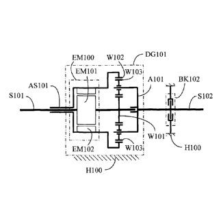
FIG. 1 is a schematic structural view showing the rotation shaft (S 101)
shared by the sun wheel (W 101) of the planetary gear set (DG 101) and the
inner rotation part of electric machine (EM101) of the dual-drive electric
machine (EM100) being served as an output/input end, the rocker arm
(A101) linked by the planetary wheel (W103) being combined with the
outer rotation part of electric machine (EM102) and combined with the
sleeve type rotation shaft (AS 101), the sleeve type rotation shaft (AS 101)
rotated and sleeved on the rotation shaft (S101) being served as an
output/input end and provided for connecting to an action side of the
controllable brake device (13K101) while the other action side of the
controllable brake device (BK101) being fixed in the housing (H 100), the
planetary gear set (DG101) also being fixed in the housing (H100), and
the outer annular wheel (W102) of the planetary gear set (DG 101) being
provided for driving the rotation shaft (S 102) to be served as an
output/input end, according to one embodiment of the present invention.
FIG 2 is a schematic structural view showing the rotation shaft (S 101)
shared by the sun wheel (W 101) of the planetary gear set (DG 101) and the
inner rotation part of electric machine (EM101) of the dual-drive electric
machine (EM100) being served as an output/input end, the rocker arm
(Al0l) linked by the planetary wheel (W103) being combined with the
2
CA 02769310 2012-02-23
outer rotation part of electric machine (EM102) and combined with the
sleeve type rotation shaft (AS 101), the sleeve type rotation shaft (AS 101)
sleeved on the rotation shaft (S 101) being served as an output/input end,
the outer annular wheel (W102) of the planetary gear set (DG101) being
provided for driving the rotation shaft (S102) to be served as an
output/input end, and the rotation shaft (S 102) being connected to an
action side of the controllable brake device (BK102) while the other
action side of the controllable brake device (BK102) being fixed in the
housing (H100), according to one embodiment of the present invention.
FIG. 3 is a schematic structural view showing the rotation shaft (S 101)
shared by the sun wheel (W 101) of the planetary gear set (DG 101) and the
inner rotation part of electric machine (EM101) of the dual-drive electric
machine (EM100) being served as an output/input end and provided for
connecting with an action side of the controllable brake device (BK103)
while the other action side of the controllable brake device (BK103) being
fixed in the housing (11100), the planetary gear set (DG101) also being
fixed in the housing (11100), the planetary wheel (W103) of the planetary
gear set (DG101) being provided for linking the rocker arm (AlOl) and
combined with the outer rotation part of electric machine (EM102) and
the sleeve type rotation shaft (AS 101), the sleeve type rotation shaft
(AS 101) being served as an output/input end, and the outer annular wheel
(W 102) of the planetary gear set (DG 101) being provided for driving the
rotation shaft (S 102) to be served as an output/input end, according to one
embodiment of the present invention.
FIG. 4 is a schematic structural view showing the controllable brake
device (BK102) being further installed between the rotation shaft (S 102)
and the housing (H100) as shown in FIG. 1.
FIG. 5 is a schematic structural view showing the controllable brake
device (BK103) being further installed between the rotation shaft (S101)
and the housing (11100) as shown in FIG 2.
3
CA 02769310 2012-02-23
FIG. 6 is a schematic structural view showing the controllable brake
device (BK1O1) being further installed between the sleeve type rotation
shaft (AS 101) and the housing (11100) as shown in FIG. 3.
FIG 7 is a schematic structural view showing the rotation shaft (S 101)
shared by the sun wheel (W 101) of the planetary gear set (DG 101) and the
inner rotation part of electric machine (EM101) of the dual-drive electric
machine (EM100) being served as an output/input end and provided for
connecting to an action side of the controllable brake device (BK103)
while the other action side of the controllable brake device (BK103) being
fixed in the housing (H 100), the planetary wheel (W103) of the planetary
gear set (DG101) is provided for linking the rocker arm (A101) and
combined with the outer rotation part of electric machine (EM102) and
combined with the sleeve type rotation shaft (AS 101), the sleeve type
rotation shaft (AS 101) being rotated and sleeved on the rotation shaft
(S 101) for being served as an output/input end, the sleeve type rotation
shaft (AS 101) being connected to an action side of the controllable brake
device (BK101) while the other action side of the controllable brake
device (BK1O1) being fixed in the housing (H100), the planetary gear set
(DG101) also being fixed in the housing (11100), and the outer annular
wheel (W102) of the planetary gear set (DG 1 O 1) being provided for
driving the rotation shaft (S 102) to be served as an output/input end, and
the rotation shaft (S 102) being connected to an action side of the
controllable brake device (BK102) while and the other action side of the
controllable brake device (BK102) being fixed in the housing (H100),
according to one embodiment of the present invention.
FIG 8 is a schematic structural view showing the rotation shaft (S 101)
shared by the sun wheel (W 101) of the planetary gear set (DG 101) and the
inner rotation part of electric machine (EM101) of the dual-drive electric
machine (EM100) being served as an output/input end, the outer annular
wheel (W102) being combined with the outer rotation part of electric
4
CA 02769310 2012-02-23
machine (EM102) and combined with the sleeve type rotation shaft
(AS 101), the sleeve type rotation shaft (AS 101) rotated and sleeved on the
rotation shaft (S101) being served as an output/input end and provided for
connecting to an action side of the controllable brake device (BK1O1)
while the other action side of the controllable brake device (BK101) being
fixed in the housing (H 100), the planetary gear set (DG 101) also being
fixed in the housing (11100), and the rocker arm (AlOl) linked by the
planetary wheel (W103) of the planetary gear set (DG1O1) being provided
for driving the rotation shaft (S 102) to be served as an output/input end,
according to one embodiment of the present invention.
FIG. 9 is a schematic structural view showing the rotation shaft (S 101)
shared by the sun wheel (W 101) of the planetary gear set (DG 101) and the
inner rotation part of electric machine (EM101) of the dual-drive electric
machine (EM100) being served as an output/input end, the outer annular
wheel (W 102) being combined with the outer rotation part of electric
machine (EM102) and combined with the sleeve type rotation shaft
(AS 101), the sleeve type rotation shaft (AS 101) sleeved on the rotation
shaft (S101) being served as an output/input end, the rocker arm (A101)
linked by the planetary wheel (W103) of the planetary gear set (DG1O1)
being provided for driving the rotation shaft (S 102) to be served as an
output/input end, and the rotation shaft (S 102) or the rocker arm (A101)
being connected to an action side of the controllable brake device
(BK102) while the other action side of the controllable brake device
(BK102) being fixed in the housing (11100), according to one embodiment
of the present invention.
FIG. 10 is a schematic structural view showing the rotation shaft
(S 101) shared by the sun wheel (W 10 1) of the planetary gear set (DG 101)
and the inner rotation part of electric machine (EM101) of the dual-drive
electric machine (EM100) being served as an output/input end and
provided for connecting to an action side of the controllable brake device
5
CA 02769310 2012-02-23
(BK103) while the other action side of the controllable brake device
(BK103) being fixed in the housing (11100), the planetary gear set
(DG 101) also being fixed in the housing (H 100), the outer annular wheel
(W102) of the planetary gear set (DG101) being combined with the outer
rotation part of electric machine (EM102) and the sleeve type rotation
shaft (AS 101), the sleeve type rotation shaft (AS 101) being served as an
output/input end, and the planetary wheel (W103) of the planetary gear set
(DG101) being provided for linking the rocker arm (A101) and driving
the rotation shaft (S 102) to be served as an output/input end, according to
one embodiment of the present invention.
FIG. 11 is a schematic structural view showing the controllable brake
device (BK102) being further installed between the rotation shaft (S 102)
and the housing (H100) as shown in FIG. 8.
FIG. 12 is a schematic structural view showing the controllable brake
device (BK103) being further installed between the rotation shaft (5101)
and the housing (H100) as shown in FIG. 9.
FIG. 13 is a schematic structural view showing the controllable brake
device (BK101) being further installed between the sleeve type rotation
shaft (AS 101) and the housing (11100) as shown in FIG. 10.
FIG. 14 is a schematic structural view showing the rotation shaft
(S101) shared by the sun wheel (W 101) of the planetary gear set (DG 101)
and the inner rotation part of electric machine (EM101) of the dual-drive
electric machine (EM100) being served as an output/input end and being
provided for connecting to an action side of the controllable brake device
(BK103) while the other action side of the controllable brake device
(BK103) being fixed in the housing (H100), the outer annular wheel
(W102) of the planetary gear set (DG101) being combined with the outer
rotation part of electric machine (EM102) and combined to the sleeve type
rotation shaft (AS 101), the sleeve type rotation shaft (AS 101) being
rotated and sleeved on the rotation shaft (S101) for being served as an
6
CA 02769310 2012-02-23
output/input end, the sleeve type rotation shaft (AS 101) being connected
to an action side of the controllable brake device (BK101) while the other
action side of the controllable brake device (BKIO1) being fixed in the
housing (H100), the planetary gear set (DG1O1) also being fixed in the
housing (H100), and the planetary wheel (W103) of the planetary gear set
(DG 101) being provided for linking the rocker arm (Al 01) and driving
the rotation shaft (S 102) to be served as an output/input end, and the
rotation shaft (S 102) or the rocker arm (A l O l) being connected to an
action side of the controllable brake device (BK102) while the other
action side of the controllable brake device (BK102) being fixed in the
housing (H100), according to one embodiment of the present invention.
FIG. 15 is a schematic structural view showing the inner rotation part
of electric machine (EM101) of the dual-drive electric machine (EM100)
and the planetary wheel (W 103) of the planetary gear set (DG 10 1) and the
rocker arm (A 101) being jointly combined on the rotation shaft (S 102) for
being served as an output/input end, the sun wheel (W 101) being
combined on the rotation shaft (S 101) for being served as an output/input
end, the outer annular wheel (W102) being combined with the outer
rotation part of electric machine (EM102) and combined with the sleeve
type rotation shaft (AS 101), the sleeve type rotation shaft (AS 101) rotated
and sleeved on the rotation shaft (S101) being served as an output/input
shaft and being provided for connecting to an action side of the
controllable brake device (BK1O1) while the other action side of the
controllable brake device (BK1O1) being fixed in the housing (H100), and
the planetary gear set (DG 101) also being fixed in the housing (11100),
according to one embodiment of the present invention..
FIG. 16 is a schematic structural view showing the inner rotation part
of electric machine (EM101) of the dual-drive electric machine (EM100)
and the planetary wheel (W103) of the planetary gear set (DG1O1) and the
rocker arm (AlOl) being jointly combined on the rotation shaft (S102) for
7
CA 02769310 2012-02-23
being served as an output/input end, the sun wheel (W101) being
combined on the rotation shaft (S101) for being served as an output/input
end, the outer annular wheel (W102) being combined with the outer
rotation part of electric machine (EM102) and combined with the sleeve
type rotation shaft (AS 101), the sleeve type rotation shaft (AS 101)
sleeved on the rotation shaft (S101) being served as an output/input shaft,
and the rotation shaft (S 102) being connected to an action side of the
controllable brake device (BK102) while the other action side of the
controllable brake device (BK102) being fixed in the housing (11100),
according to one embodiment of the present invention.
FIG. 17 is a schematic structural view showing the inner rotation part
of electric machine (EM101) of the dual-drive electric machine (EM100)
and the planetary wheel (W103) of the planetary gear set (DG101) and the
rocker arm (A101) being jointly combined on the rotation shaft (S 102) for
being served as an output/input end, the sun wheel (W101) being
combined on the rotation shaft (S 10 1) for being served as an output/input
end, the rotation shaft (S101) being connected to an action side of the
controllable brake device (BK103) while the other action side of the
controllable brake device (BK103) being fixed in the housing (11100), the
planetary gear set (DG1O1) also being fixed in the housing (H100), the
outer annular wheel (W 102) of the planetary gear set (DG 101) being
combined with the outer rotation part of electric machine (EM102) and
combined with the sleeve type rotation shaft (AS 101), and the sleeve type
rotation shaft (AS 101) being served as an output/input end, according to
one embodiment of the present invention.
FIG. 18 is a schematic structural view showing the controllable brake
device (BK102) being further installed between the rotation shaft (S 102)
and the housing (H 100) as shown in FIG. 15.
FIG. 19 is a schematic structural view showing the controllable brake
device (BK103) being further installed between the rotation shaft (5101)
8
CA 02769310 2012-02-23
and the housing (H100) as shown in FIG. 16.
FIG. 20 is a schematic structural view showing the controllable brake
device (13K101) being further installed between the sleeve type rotation
shaft (AS 101) and the housing (H 100) as shown in FIG 17.
FIG. 21 is a schematic structural view showing the inner rotation part
of electric machine (EM 101) of the dual-drive electric machine (EM 100)
and the planetary wheel (W103) of the planetary gear set (DG101) and the
rocker arm (A101) being jointly combined on the rotation shaft (S 102) for
being served as an output/input end, and the sun wheel (W101) being
combined on the rotation shaft (S 101) for being served as an output/input
end, the rotation shaft (S101) being connected to an action side of the
controllable brake device (BK103) while the other action side of the
controllable brake device (BK103) being fixed in the housing (H100), the
outer annular wheel (W 102) of the planetary gear set (DG 101) being
combined with the outer rotation part of electric machine (EM102) and
combined to the sleeve type rotation shaft (AS 101), the sleeve type
rotation shaft (AS 101) being rotated and sleeved on the rotation shaft
(S101) for being served as an output/input end, the sleeve type rotation
shaft (AS 101) being connected to an action side of the controllable brake
device (13K101) while the other action side of the controllable brake
device (13K101) being fixed in the housing (H100), the planetary gear set
(DG101) also being fixed in the housing (H100), and the rotation shat
(S102) being connected to an action side of the controllable brake device
(BK102) while the other action side of the controllable brake device
(BK102) being fixed in the housing (H100), according to one embodiment
of the present invention.
DESCRIPTION OF MAIN COMPONENT SYMBOLS
A101 : Rocker arm
AS 101: Sleeve type rotation shaft
9
CA 02769310 2012-02-23
BK101, BK102, BK103 : Controllable brake device
DG 101: Planetary gear set
EM100 : Dual-drive electric machine
EM 101: Inner rotation part of electric machine
EM102 : Outer rotation part of electric machine
H100 : Housing
S101 S102 : Rotation shaft
W101 : Sun wheel
W102 : Outer annular wheel
W103 : Planetary wheel
DETAILED DESCRIPTION OF THE PREFERRED EMBODIMENTS
Conventionally, a friction type electromagnetic clutch device is often
installed between the output/input end of a rotation electric machine and a
load; and through electrically charging or breaking the friction type
electromagnetic clutch device to perform operations of combining or
releasing, the load is enabled to engaged or released with the rotary
electric machine. One primary disadvantage of the conventional arts is
that residual rotary torque is often remained during the releasing, which
may cause the kinetic energy loss and the ineffective operation.
The present invention provides a dual-drive electric machine having a
controllable planetary gear set, in which an inner rotation part of the
electric machine (EM101) of the dual-drive electric machine (EM100)
being combined with a sun wheel (W101) of an planetary gear set
(DG 101) and combined with a rotation shaft (S101) shared by the above
two is served as an output/input end, a rotation shaft (S 102) combined
with an outer annular wheel (W102) is served as an output/input end, and
a rocker arm (A101) linked by an planetary wheel (W103) of the
planetary gear set (DG 101) combined with an outer rotation part of
electric machine (EM102) and combined with a sleeve type rotation shaft
CA 02769310 2012-02-23
(AS 101) is served as an output/input end, so that a part or all of the three
output/input ends are respectively connected to an action side of a
corresponding controllable brake device, and the other action side of the
controllable brake device is connected to a housing (H 100); through
controlling the controllable brake device to perform brake locking or
releasing, the operations of transmission function of connecting
transmission or releasing between the rotation shaft (S101) at the
output/input end, the rotation shaft (S 102) at the output/input end and the
sleeve type rotation shaft (AS 101) at the output/input end of the planetary
gear set (DG1O1) are enabled to be controlled, and the interactive
operations between the dual-drive electric machine (EM100) and the
output/input ends are also enabled to be controlled.
The structures and embodiments of the dual-drive electric machine
having controllable planetary gear set of the present invention are
disclosed as followings:
FIG. 1 is a schematic structural view showing the rotation shaft (S 101)
shared by the sun wheel (W 101) of the planetary gear set (DG 101) and the
inner rotation part of electric machine (EM101) of the dual-drive electric
machine (EM100) being served as an output/input end, the rocker arm
(AlOl) linked by the planetary wheel (W103) being combined with the
outer rotation part of electric machine (EM102) and combined with the
sleeve type rotation shaft (AS 101), the sleeve type rotation shaft (AS 101)
rotated and sleeved on the rotation shaft (S 101) being served as an
output/input end and provided for connecting to an action side of the
controllable brake device (BK1O1) while the other action side of the
controllable brake device (BK1 O 1) being fixed in the housing (H 100), the
planetary gear set (DG1O1) also being fixed in the housing (H100), and
the outer annular wheel (W102) of the planetary gear set (DG 101) being
provided for driving the rotation shaft (S102) to be served as an
output/input end, according to one embodiment of the present invention.
11
CA 02769310 2012-02-23
As show in FIG 1, it mainly consists of:
-- Planetary gear set (DG 101): which is constituted by an sun wheel
(W101) and an outer annular wheel (W102) and at least an planetary
wheel (W103), and including through gears engaging with each other, or
through friction wheels mutually performing friction transmissions to
form an planetary gear set function, and structured by the rotation shaft
(S101), the rotation shaft (S102), the rocker arm (Al O l ), the sleeve type
rotation shaft (AS101) and a bearing, as well as installed with a shell for
being combined in the housing (H100);
--Rocker arm (AlOl): having one end provided for allowing the planetary
wheel (W103) to rotate and link, and the other end axially extending
toward the rotation shaft (S101) for being combined with the outer
rotation part of electric machine (EM102) and combined with the sleeve
type rotation shaft (AS 101), and the sleeve type rotation shaft (AS 101) is
sleeved on one or both of the rotation shaft (S101) and the rotation shaft
(S 102) and capable of rotating thereon;
--Controllable brake device (BK101): which is constituted by a brake
device controlled by a manual force or mechanical force or hydraulic
force or pneumatic force or electromagnetic force, and having two
controllable action sides for the operations of a brake locking state for
engagement or a releasing state for separation, wherein one of the action
sides is connected to the sleeve type rotation shaft (AS101) or the rocker
arm (A101), and the other action side is fixed in the housing (H100);
--Dual-drive electric machine (EM100): which is constituted by a DC or
AC, brush or brushless, synchronous or non-synchronous dual-drive
electric machine, having an inner rotation part of electric machine
(EM101) and an outer rotation part of electric machine (EM102), and
installed with end covers, bearings and related electric conduction devices
used to introduce electric energy, the inner rotation part of electric
machine (EM101) and the outer rotation part of electric machine (EM102)
12
CA 02769310 2012-02-23
are coaxially rotated, wherein the inner rotation part of electric machine
(EM 101) is combined with the rotation shaft (S101), and the outer
rotation part of electric machine (EM102) is combined with the rocker
arm (A 101);
--The rotation shaft (S l O l) shared by the sun wheel (W101) of the
planetary gear set (DG1O1) and the inner rotation part of electric machine
(EM 101) of the dual-drive electric machine (EM100) is served as an
output/input end, the rocker arm (A101) linked by the planetary wheel
(W103) is combined with the outer rotation part of electric machine
(EM 102) and combined with the sleeve type rotation shaft (AS 101), and
the sleeve type rotation shaft (AS 101) rotated and sleeved on the rotation
shaft (S101) is served as an output/input end, and the sleeve type rotation
shaft (AS 101) is connected to an action side of the controllable brake
device (BK1 O1) while the other action side of the controllable brake
device (BK101) is fixed in the housing (11100), and the outer annular
wheel (W102) of the planetary gear set (DG1O1) is provided for driving
the rotation shaft (S 102) to be served as an output/input end, and the
rotation shaft (S 101) connected with the sun wheel (W 101) is also served
as an output/input end;
According to the embodiment shown in FIG. 1, the operations include
one or more than one of following functions:
--When the controllable brake device (BK101) is controlled to be in the
releasing state, and the dual-drive electric machine (EM100) is not
operated as the electric machinery function, the transmission relations
between the rotation shaft (S101) and the rotation shaft (S 102) and the
sleeve type rotation shaft (AS 101) are in the releasing state allowing idle
rotation;
-- When the controllable brake device (BK101) is controlled to be in the
releasing state, and the dual-drive electric machine (EM 100) is operated
as the electric machinery function, the corresponding interactive
13
CA 02769310 2012-02-23
operations of the power generator function or the motor function are
correspondingly performed between the inner rotation part of electric
machine (EM101) and the outer rotation part of electric machine
(EM102), according to the damping of external load or the rotation torque,
the rotation speed and the rotation direction of the externally inputted
rotary kinetic energy sustained by the rotation shaft (S 101), the rotation
shaft (S 102) and the sleeve type rotation shaft (AS 101);
--When the controllable brake device (BK101) is controlled to be in the
brake locking state, and the dual-drive electric machine (EM100) is not
operated as the electric machinery function, the transmission relation
between the rotation shaft (S 101) and the rotation shaft (S 102) is in a
connecting relation allowing for transmission;
--When the controllable brake device (BK101) is controlled to be in the
brake locking state, and the dual-drive electric machine (EM100) is
operated as the electric machinery function, between the inner rotation
part of the electric machine (EM101) and the outer rotation part of the
electric machine (EM102) is operated as the power generator function or
the motor function for performing interactive operations according to the
damping of the external load or the externally inputted rotary kinetic
energy sustained by the rotation shaft (S 101) and the rotation shaft
(S 102);
The interactive operations of corresponding function performed by the
mentioned dual-drive electric machine (EM100) include receiving the
driving control of externally inputted electric energy to operate as the
motor function for individually driving the load, or working with the
externally inputted rotary kinetic energy for commonly driving the load;
The interactive operations of corresponding function performed by the
mentioned dual-drive electric machine (EM100) include receiving the
driving of the externally inputted rotary kinetic energy or the driving of
the load inertia kinetic energy for being operated as the power generator
14
CA 02769310 2012-02-23
function, so as to output the electric energy to drive the external electric
load or charge the external electric energy storing device.
FIG. 2 is a schematic structural view showing the rotation shaft (S 101)
shared by the sun wheel (W 101) of the planetary gear set (DG 101) and the
inner rotation part of electric machine (EM101) of the dual-drive electric
machine (EM100) being served as an output/input end, the rocker arm
(A101) linked by the planetary wheel (W103) being combined with the
outer rotation part of electric machine (EM102) and combined with the
sleeve type rotation shaft (AS 101), the sleeve type rotation shaft (AS 101)
sleeved on the rotation shaft (S 101) being served as an output/input end,
the outer annular wheel (W 102) of the planetary gear set (DG101) being
provided for driving the rotation shaft (S 102) to be served as an
output/input end, and the rotation shaft (S 102) being connected to an
action side of the controllable brake device (BK102) while the other
action side of the controllable brake device (BK102) being fixed in the
housing (H100), according to one embodiment of the present invention.
As show in FIG 2, it mainly consists of-
-- Planetary gear set (DG 101): which is constituted by an sun wheel
(W101) and an outer annular wheel (W 102) and at least an planetary
wheel (W103), and including through gears engaging with each other, or
through friction wheels mutually performing friction transmissions to
form an planetary gear set function, and structured by the rotation shaft
(S 101), the rotation shaft (S 102), the rocker arm (A 101), the sleeve type
rotation shaft (AS 101) and a bearing, as well as installed with a shell for
being combined in the housing (H 100);
--Rocker arm (A101): having one end provided for allowing the planetary
wheel (W103) to rotate and link, and the other end axially extending
toward the rotation shaft (S101) for being combined with the outer
rotation part of electric machine (EM102) and combined with the sleeve
type rotation shaft (AS 101), and the sleeve type rotation shaft (AS 101) is
CA 02769310 2012-02-23
sleeved on one or both of the rotation shaft (S 101) and the rotation shaft
(S 102) and capable of rotating thereon;
--Controllable brake device (BK102): which is constituted by a brake
device controlled by a manual force or mechanical force or hydraulic
force or pneumatic force or electromagnetic force, and having two
controllable action sides for the operations of a brake locking state for
engagement or a releasing state for separation, wherein one of the action
sides is connected to the rotation shaft (S102), and the other action side is
fixed in the housing (H100);
--Dual-drive electric machine (EM100): which is constituted by a DC or
AC, brush or brushless, synchronous or non-synchronous dual-drive
electric machine, having an inner rotation part of electric machine
(EM101) and an outer rotation part of electric machine (EM102), and
installed with end covers, bearings and related electric conduction devices
used to introduce electric energy, the inner rotation part of electric
machine (EMI 01) and the outer rotation part of electric machine (EM 102)
are coaxially rotated, wherein the inner rotation part of electric machine
(EM 101) is combined with the rotation shaft (S 101), and the outer
rotation part of electric machine (EM102) is combined with the rocker
arm (A101);
--The rotation shaft (S 101) shared by the sun wheel (W 101) of the
planetary gear set (DG101) and the inner rotation part of electric machine
(EM 101) of the dual-drive electric machine (EM 100) is served as an
output/input end, the rocker arm (Al01) linked by the planetary wheel
(W 103) is combined with the outer rotation part of electric machine
(EM102) and combined with the sleeve type rotation shaft (AS 101), and
the sleeve type rotation shaft (AS 101) rotated and sleeved on the rotation
shaft (S 101) is served as an output/input end;
--The outer annular wheel (W 102) of the planetary gear set (DG 101) is
provided for driving the rotation shaft (S 102) to be served as an
16
CA 02769310 2012-02-23
output/input end, and the rotation shaft (S102) is connected to an action
side of the controllable brake device (BK102) while the other action side
of the controllable brake device (BK102) is fixed in the housing (H100);
According to the embodiment shown in FIG 2, the operations include
one or more than one of following functions:
--When the controllable brake device (BK102) is controlled to be in the
releasing state, and the dual-drive electric machine (EM100) is not
operated as the electric machinery function, the transmission relations
between the rotation shaft (S 101) and the sleeve type rotation shaft
(AS 101) and the rotation shaft (S 102) are in the releasing state allowing
idle rotation;
-- When the controllable brake device (BK102) is controlled to be in the
releasing state, and the dual-drive electric machine (EM100) is operated
as the electric machinery function, the corresponding interactive
operations of the power generator function or the motor function are
correspondingly performed between the inner rotation part of electric
machine (EM101) and the outer rotation part of electric machine
(EM102), according to the damping of the external load or the rotation
torque, the rotation speed and the rotation direction of the externally
inputted rotary kinetic energy sustained by the rotation shaft (S 101), the
rotation shaft (S 102) and the sleeve type rotation shaft (AS 101);
--When the controllable brake device (BK102) is controlled to be in the
brake locking state, and the dual-drive electric machine (EM100) is not
operated as the electric machinery function, the transmission relation
between the rotation shaft (S 101) and the sleeve type rotation shaft
(AS 101) is in a connecting relation allowing for transmission;
--When the controllable brake device (BK102) is controlled to be in the
brake locking state, and the dual-drive electric machine (EM100) is
operated as the electric machinery function, between the inner rotation
part of the electric machine (EM101) and the outer rotation part of the
17
CA 02769310 2012-02-23
electric machine (EM102) is operated as the power generator function or
the motor function for performing interactive operations according to
the damping of the external load or the externally inputted rotary kinetic
energy sustained by the rotation shaft (S 101) and the sleeve type rotation
shaft (AS 101);
The interactive operations of corresponding function performed by the
mentioned dual-drive electric machine (EM100) include receiving the
driving control of externally inputted electric energy to operate as the
motor function for individually driving the load, or working with the
externally inputted rotary kinetic energy for commonly driving the load;
The interactive operations of corresponding function performed by the
mentioned dual-drive electric machine (EM100) include receiving the
driving of the externally inputted rotary kinetic energy or the driving of
the load inertia kinetic energy for being operated as the power generator
function, so as to output the electric energy to drive the external electric
load or charge the external electric energy storing device.
FIG. 3 is a schematic structural view showing the rotation shaft (S101)
shared by the sun wheel (W 101) of the planetary gear set (DG 101) and the
inner rotation part of electric machine (EM101) of the dual-drive electric
machine (EM100) being served as an output/input end and provided for
connecting with an action side of the controllable brake device (BK103)
while the other action side of the controllable brake device (BK103) being
fixed in the housing (H100), the planetary gear set (DG101) also being
fixed in the housing (H 100), the planetary wheel (W103) of the planetary
gear set (DG101) being provided for linking the rocker arm (A101) and
combined with the outer rotation part of electric machine (EM102) and
the sleeve type rotation shaft (AS 101), the sleeve type rotation shaft
(AS 101) being served as an output/input end, and the outer annular wheel
(W102) of the planetary gear set (DG 101) being provided for driving the
rotation shaft (S 102) to be served as an output/input end, according to one
18
CA 02769310 2012-02-23
embodiment of the present invention.
As show in FIG 3, it mainly consists of-
-- Planetary gear set (DG101): which is constituted by an sun wheel
(W 101) and an outer annular wheel (W 102) and at least an planetary
wheel (W103), and including through gears engaging with each other, or
through friction wheels mutually performing friction transmissions to
form an planetary gear set function, and structured by the rotation shaft
(S 101), the rotation shaft (S 102), the rocker arm (A 101), the sleeve type
rotation shaft (AS 101) and a bearing, as well as installed with a shell for
being combined in the housing (H100);
--Rocker arm (A101): having one end provided for allowing the planetary
wheel (W103) to rotate and link, and the other end axially extending
toward the rotation shaft (S 101) for being combined with the outer
rotation part of electric machine (EM102) and combined with the sleeve
type rotation shaft (AS 101), and the sleeve type rotation shaft (AS 101) is
sleeved on one or both of the rotation shaft (S 101) and the rotation shaft
(S 102) and capable of rotating thereon;
--Controllable brake device (BK103): which is constituted by a brake
device controlled by a manual force or mechanical force or hydraulic
force or pneumatic force or electromagnetic force, and having two
controllable action sides for the operations of a brake locking state for
engagement or a releasing state for separation, wherein one of the action
sides is connected to the rotation shaft (S 101), and the other action side is
fixed in the housing (H 100);
--Dual-drive electric machine (EM100): which is constituted by a DC or
AC, brush or brushless, synchronous or non-synchronous dual-drive
electric machine, having an inner rotation part of electric machine
(EM 101) and an outer rotation part of electric machine (EM 102), and
installed with end covers, bearings and related electric conduction devices
used to introduce electric energy, the inner rotation part of electric
19
CA 02769310 2012-02-23
machine (EM 101) and the outer rotation part of electric machine (EM 102)
are coaxially rotated, wherein the inner rotation part of electric machine
(EM 101) is combined with the rotation shaft (S 101), and the outer
rotation part of electric machine (EM102) is combined with the rocker
arm (A101);
--The rotation shaft (S 101) shared by the sun wheel (W 101) of the
planetary gear set (DG1O1) and the inner rotation part of electric machine
(EM1O1) of the dual-drive electric machine (EM100) is served as an
output/input end for connecting to an action side of the controllable brake
device (BK103) while the other action side of the controllable brake
device (BK103) is fixed in the housing (H100);
--The planetary wheel (W103) of the planetary gear set (DG1O1) is
provided for linking the rocker arm (AlOl) and combined with the outer
rotation part of electric machine (EM102) and combined with the sleeve
type rotation shaft (AS 101), the sleeve type rotation shaft (AS 101) rotated
and sleeved on the rotation shaft (S 1 O 1) is served as an output/input end,
the outer annular wheel (W102) of the planetary gear set (DG 1 O 1) is
provided for driving the rotation shaft (S102) to be served as an
output/input end, and the rotation shaft (S 101) connected to the sun wheel
(W101) is also served as an output/input end;
According to the embodiment shown in FIG 3, the operations include
one or more than one of following functions:
--When the controllable brake device (BK103) is controlled to be in the
releasing state, and the dual-drive electric machine (EM100) is not
operated as the electric machinery function, the transmission relation
between the rotation shaft (S 101) and the sleeve type rotation shaft
(AS 101) and the rotation shaft (S 102) are in the releasing state allowing
idle rotation;
-- When the controllable brake device (BK103) is controlled to be in the
releasing state, and the dual-drive electric machine (EM100) is operated
CA 02769310 2012-02-23
as the electric machinery function, the corresponding interactive
operations of the power generator function or the motor function are
correspondingly performed between the inner rotation part of electric
machine (EM101) and the outer rotation part of electric machine
(EM102), according to the damping of the external load or the rotation
torque, the rotation speed and the rotation direction of the externally
inputted rotary kinetic energy sustained by the rotation shaft (S 101), the
rotation shaft (S 102) and the sleeve type rotation shaft (AS 101);
--When the controllable brake device (BK103) is controlled to be in the
brake locking state, and the dual-drive electric machine (EM100) is not
operated as the electric machinery function, the transmission relation
between the sleeve type rotation shaft (AS 101) and the rotation shaft
(S 102) is in a connecting relation allowing for transmission;
--When the controllable brake device (BK103) is controlled to be in the
brake locking state, and the dual-drive electric machine (EM100) is
operated as the electric machinery function, between the inner rotation
part of electric machine (EM101) and the outer rotation part of electric
machine (EM102) is operated as the power generator function or the
motor function for performing interactive operations according to the
damping of the external load or the externally inputted rotary kinetic
energy sustained by the sleeve type rotation shaft (AS 101) and the
rotation shaft (S 102);
The interactive operations of corresponding function performed by the
mentioned dual-drive electric machine (EM100) include receiving the
driving control of externally inputted electric energy to operate as the
motor function for individually driving the load, or working with the
externally inputted rotary kinetic energy for commonly driving the load;
The interactive operations of corresponding function performed by the
mentioned dual-drive electric machine (EM100) include receiving the
driving of the externally inputted rotary kinetic energy or the driving of
21
CA 02769310 2012-02-23
the load inertia kinetic energy for being operated as the power generator
function, so as to output the electric energy to drive the external electric
load or charge the external electric energy storing device.
FIG. 4 is a schematic structural view showing the controllable brake
device (BK102) being further installed between the rotation shaft (S102)
and the housing (11100) as shown in FIG. 1.
As shown in FIG. 4, the rotation shaft (S 101) shared by the sun wheel
(W101) of the planetary gear set (DG 101) and the inner rotation part of
electric machine (EM 101) of the dual-drive electric machine (EM 100) is
served as an output/input end, the rocker arm (A101) linked by the
planetary wheel (W103) is combined with the outer rotation part of
electric machine (EM102) and combined with the sleeve type rotation
shaft (AS 101), and the sleeve type rotation shaft (AS 101) rotated and
sleeved on the rotation shaft (SlOl) is served as an output/input end, the
sleeve type rotation shaft (AS 101) is connected to an action side of the
controllable brake device (BK101) while the other action side of the
controllable brake device (BK101) is fixed in the housing (H100), the
planetary gear set (DG101) is also fixed in the housing (H100), the outer
annular wheel (W102) of the planetary gear set (DG 101) is provided for
driving the rotation shaft (S 102) to be served as an output/input end, and
the rotation shaft (S 102) is connected to an action side of the controllable
brake device (BK102) while the other action side of the controllable brake
device (BK102) is fixed in the housing (11100), which mainly consists of.
-- Planetary gear set (DG101): which is constituted by an sun wheel
(W101) and an outer annular wheel (W102) and at least an planetary
wheel (W103), and including through gears engaging with each other, or
through friction wheels mutually performing friction transmissions to
form an planetary gear set function, and structured by the rotation shaft
(S l O l ), the rotation shaft (S102), the rocker arm (A 101), the sleeve type
rotation shaft (AS 101) and a bearing, as well as installed with a shell for
22
CA 02769310 2012-02-23
being combined in the housing (H100);
--Rocker arm (AlOl): having one end provided for allowing the planetary
wheel (W 103) to rotate and link, and the other end axially extending
toward the rotation shaft (S 101) for being combined with the sleeve type
rotation shaft (AS 101), and the sleeve type rotation shaft (AS 101) is
sleeved on one or both of the rotation shaft (S 101) and the rotation shaft
(S 102) and capable of rotating thereon;
--Controllable brake device (BK101): which is constituted by a brake
device controlled by a manual force or mechanical force or hydraulic
force or pneumatic force or electromagnetic force, and having two
controllable action sides for the operations of a brake locking state for
engagement or a releasing state for separation, wherein one of the action
sides is connected to the sleeve type rotation shaft (AS 101) or the rocker
arm (AlOl), and the other action side is fixed in the housing (H100);
--Controllable brake device (BK102): which is constituted by a brake
device controlled by a manual force or mechanical force or hydraulic
force or pneumatic force or electromagnetic force, and having two
controllable action sides for the operations of a brake locking state for
engagement or a releasing state for separation, wherein one of the action
sides is connected to the rotation shaft (S102), and the other action side is
fixed in the housing (H 100);
--Dual-drive electric machine (EM100): which is constituted by a DC or
AC, brush or brushless, synchronous or non-synchronous dual-drive
electric machine, having an inner rotation part of electric machine
(EM101) and an outer rotation part of electric machine (EM102), and
installed with end covers, bearings and related electric conduction devices
used to introduce electric energy, the inner rotation part of electric
machine (EM101) and the outer rotation part of electric machine (EM102)
are coaxially rotated, wherein the inner rotation part of electric machine
(EM 101) is combined with the rotation shaft (S 101), and the outer
23
CA 02769310 2012-02-23
rotation part of electric machine (EM102) is combined with the rocker
arm (A101);
--The rotation shaft (S101) shared by the sun wheel (W101) of the
planetary gear set (DG1O1) and the inner rotation part of electric machine
(EM101) of the dual-drive electric machine (EM100) is served as an
output/input end, the outer annular wheel (W102) of the planetary gear set
(DG 101) combined with the rotation shaft (S 102) is served as an
output/input end, the rocker arm (AlOl) linked by the planetary wheel
(W103) is combined with the outer rotation part of electric machine
(EM 102) and combined with the sleeve type rotation shaft (AS 101), and
the sleeve type rotation shaft (AS 101) rotated and sleeved on the rotation
shaft (S 101) is served as an output/input end, and the sleeve type rotation
shaft (AS 101) is connected to an action side of the controllable brake
device (BK1O1) while the other action side of the controllable brake
device (BK101) is fixed in the housing (H100), the outer annular wheel
(W 102) of the planetary gear set (DG 101) is provided for driving the
rotation shaft (S 102) to be served as an output/input end, and the rotation
shaft (S 102) is connected to an action side of the controllable brake device
(BK102) while the other action side of the controllable brake device
(BK102) is fixed in the housing (H100);
According to the embodiment shown in FIG 4, the operations include
one or more than one of following functions:
--When the controllable brake device (BK1O1) and the controllable brake
device (BK102) are both controlled to be in the releasing state, and the
dual-drive electric machine (EM100) is not operated as the electric
machinery function, the transmission relations between the rotation shaft
(S l O l) and the rotation shaft (S 102) and the sleeve type rotation shaft
(AS 101) are in the releasing state allowing idle rotation;
-- When the controllable brake device (BK1O1) and the controllable brake
device (BK102) are both controlled to be in the releasing state, and the
24
CA 02769310 2012-02-23
dual-drive electric machine (EM 100) is operated as the electric machinery
function, the corresponding interactive operations of the power generator
function or the motor function are correspondingly performed between the
inner rotation part of electric machine (EM101) and the outer rotation part
of electric machine (EM102), according to the damping of the external
load or the rotation torque, the rotation speed and the rotation direction of
the externally inputted rotary kinetic energy sustained by the rotation shaft
(S 101), the rotation shaft (S 102) and the sleeve type rotation shaft
(AS 101);
--When the controllable brake device (BK101) is controlled to be in the
brake locking state and the controllable brake device (BK102) is
controlled to be in the releasing state, and the dual-drive electric machine
(EM100) is not operated as the electric machinery function, the
transmission relation between the rotation shaft (S 101) and the rotation
shaft (S 102) is in a connecting relation allowing for transmission;
--When the controllable brake device (BK101) is controlled to be in the
brake locking state and the controllable brake device (BK102) is
controlled to be in the releasing state, and the dual-drive electric machine
(EM 100) is operated as the electric machinery function, between the inner
rotation part of electric machine (EM101) and the outer rotation part of
electric machine (EM102) is operated as the power generator function or
the motor function for performing corresponding interactive operations
with the damping of the external load or the externally inputted rotary
kinetic energy sustained by the rotation shaft (S 101) and the rotation shaft
(S 102);
--When the controllable brake device (BK101) is controlled to be in the
releasing state and the controllable brake device (BK102) is controlled to
be in the brake locking state, and the dual-drive electric machine (EM 100)
is not operated as the electric machinery function, the transmission
relation between the rotation shaft (S 101) and the sleeve type rotation
CA 02769310 2012-02-23
shaft (AS 101) is in a connecting relation allowing for transmission;
--When the controllable brake device (BK101) is controlled to be in the
releasing state and the controllable brake device (BK102) is controlled to
be in the brake locking state, and the dual-drive electric machine (EM 100)
is operated as the electric machinery function, between the inner rotation
part of the electric machine (EM101) and the outer rotation part of the
electric machine (EM 102) is operated as the power generator function or
the motor function, for performing corresponding interactive operations
with the damping of external load or the externally inputted rotary kinetic
energy sustained by the rotation shaft (S 101) and the sleeve type rotation
shaft (AS 101);
--When the controllable brake device (BK101) and the controllable brake
device (BK102) are both controlled to be in the brake locking state, the
relations between the rotation shaft (S 101), the rotation shaft (S 102) and
the sleeve type rotation shaft (AS 101) are all in the brake locking state;
The interactive operations of corresponding function performed by the
mentioned dual-drive electric machine (EM100) include receiving the
driving control of externally inputted electric energy to operate as the
motor function for individually driving the load, or working with the
externally inputted rotary kinetic energy for commonly driving the load;
The interactive operations of corresponding function performed by the
mentioned dual-drive electric machine (EM100) include receiving the
driving of the externally inputted rotary kinetic energy or the driving of
the load inertia kinetic energy for being operated as the power generator
function, so as to output the electric energy to drive the external electric
load or charge the external electric energy storing device.
FIG. 5 is a schematic structural view showing the controllable brake
device (BK103) being further installed between the rotation shaft (5101)
and the housing (H100) as shown in FIG 2.
As shown in FIG. 5, the rotation shaft (S 101) shared by the sun wheel
26
CA 02769310 2012-02-23
(W 101) of the planetary gear set (DG101) and the inner rotation part of
electric machine (EM 101) of the dual-drive electric machine (EM 100) is
served as an output/input end and provided for connecting to an action
side of the controllable brake device (BK103) while the other action side
of the controllable brake device (BK103) is fixed in the housing (H100),
the planetary gear set (DG101) is also fixed in the housing (H100), the
planetary wheel (W103) of the planetary gear set (DG101) is provided for
linking the rocker arm (AlOl) and combined with the outer rotation part
of electric machine (EM102) and combined with the sleeve type rotation
shaft (AS 101), and the sleeve type rotation shaft (AS 101) rotated and
sleeved on the rotation shaft (S 101) is served as an output/input end, the
outer annular wheel (W 102) of the planetary gear set (DG 101) is provided
for driving the rotation shaft (S 102) to be served as an output/input end,
and the rotation shaft (S 102) is connected to an action side of the
controllable brake device (BK102) while the other action side of the
controllable brake device (BK102) is fixed in the housing (H100), which
mainly consists of-
--Planetary gear set (DG101): which is constituted by an sun wheel
(W 101) and an outer annular wheel (W 102) and at least an planetary
wheel (W103), and including through gears engaging with each other, or
through friction wheels mutually performing friction transmissions to
form an planetary gear set function, and structured by the rotation shaft
(S 101), the rotation shaft (S 102), the rocker arm (A101), the sleeve type
rotation shaft (AS 101) and a bearing, as well as installed with a shell for
being combined in the housing (H100);
--Rocker arm (Al01): having one end provided for allowing the planetary
wheel (W103) to rotate and link, and the other end axially extending
toward the rotation shaft (S 101) for being combined with the sleeve type
rotation shaft (AS 101), and the sleeve type rotation shaft (AS 101) is
sleeved on one or both of the rotation shaft (S 101) and the rotation shaft
27
CA 02769310 2012-02-23
(S 102) and capable of rotating thereon;
--Controllable brake device (BK102): which is constituted by a brake
device controlled by a manual force or mechanical force or hydraulic
force or pneumatic force or electromagnetic force, and having two
controllable action sides for the operations of a brake locking state for
engagement or a releasing state for separation, wherein one of the action
sides is connected the rotation shaft (S 102), and the other action side is
fixed in the housing (H 100);
--Controllable brake device (BK103): which is constituted by a brake
device controlled by a manual force or mechanical force or hydraulic
force or pneumatic force or electromagnetic force, and having two
controllable action sides for the operations of a brake locking state for
engagement or a releasing state for separation, wherein one of the action
sides is connected to the rotation shaft (S 1 O 1), and the other action side
is
fixed in the housing (H100);
--Dual-drive electric machine (EM100): which is constituted by a DC or
AC, brush or brushless, synchronous or non-synchronous dual-drive
electric machine, having an inner rotation part of electric machine
(EM1O1) and an outer rotation part of electric machine (EM102), and
installed with end covers, bearings and related electric conduction devices
used to introduce electric energy, the inner rotation part of electric
machine (EM 101) and the outer rotation part of electric machine (EM 102)
are coaxially rotated, wherein the inner rotation part of electric machine
(EM 101) is combined with the rotation shaft (S 101), and the outer
rotation part of electric machine (EM102) is combined with the rocker
arm (A l O l );
-- The rotation shaft (S 101) shared by the sun wheel (W 1 O 1) of the
planetary gear set (DG1O1) and the inner rotation part of electric machine
(EM1O1) of the dual-drive electric machine (EM100) is served as an
output/input end, and is provided for connecting to an action side of the
28
CA 02769310 2012-02-23
controllable brake device (BK103) while the other action side of the
controllable brake device (BK103) is fixed in the housing (H100); the
outer annular wheel (W102) of the planetary gear set (DG1O1) is
combined with the rotation shaft (S102) for being served as an
output/input end, and is provided for connecting to an action side of the
controllable brake device (BK102) while the other action side of the
controllable brake device (BK102) is fixed in the housing (H100), the
rocker arm (A l O l) linked by the planetary wheel (W103) is combined
with the outer rotation part of electric machine (EM102) and combined
with the sleeve type rotation shaft (AS 101), and the sleeve type rotation
shaft (AS 1 O 1) rotated and sleeved on the rotation shaft (S 101) is served
as
an output/input end;
According to the embodiment shown in FIG. 5, the operations include
one or more than one of following functions:
--When the controllable brake device (BK102) and the controllable brake
device (BK103) are both controlled to be in the releasing state, and the
dual-drive electric machine (EM100) is not operated as the electric
machinery function, the transmission relations between the rotation shaft
(S 101) and the rotation shaft (S 102) and the sleeve type rotation shaft
(AS 101) are in the releasing state allowing idle rotation;
-- When the controllable brake device (BK102) and the controllable brake
device (BK103) are both controlled to be in the releasing state, and the
dual-drive electric machine (EM 100) is operated as the electric machinery
function, the corresponding interactive operation of the power generator
function or the motor function are correspondingly performed between the
inner rotation part of electric machine (EM 101) and the outer rotation part
of electric machine (EM102), according to the damping of the external
load or the rotation torque, the rotation speed and the rotation direction of
the externally inputted rotary kinetic energy sustained by the rotation shaft
(S l O l ), the rotation shaft (S 102) and the sleeve type rotation shaft
29
CA 02769310 2012-02-23
(AS 101);
--When the controllable brake device (BK103) is controlled to be in the
brake locking state and the controllable brake device (BK102) is
controlled to be in the releasing state, and the dual-drive electric machine
(EM100) is not operated as the electric machinery function, the
transmission relation between the sleeve type rotation shaft (AS 101) and
the rotation shaft (S 102) is in a connecting relation allowing for
transmission;
--When the controllable brake device (BK103) is controlled to be in the
brake locking state and the controllable brake device (BK102) is
controlled to be in the releasing state, and the dual-drive electric machine
(EM100) is operated with the electric machinery function, between the
inner rotation part of the electric machine (EM101) and the outer rotation
part of the electric machine (EM102) is operated as the power generator
function or the motor function, for performing corresponding interactive
operations with the damping of external load or the externally inputted
rotary kinetic energy sustained by the sleeve type rotation shaft (AS 101)
and the rotation shaft (S 102);
--When the controllable brake device (BK103) is controlled to be in the
releasing state and the controllable brake device (BK102) is controlled to
be in the brake locking state, and the dual-drive electric machine (EM100)
is not operated as the electric machinery function, the transmission
relation between the rotation shaft (S 101) and the sleeve type rotation
shaft (AS 101) is in a connecting relation allowing for transmission;
--When the controllable brake device (BK103) is controlled to be in the
releasing state and the controllable brake device (BK102) is controlled to
be in the brake locking state, and the dual-drive electric machine (EM 100)
is operated as the electric machinery function, between the inner rotation
part of the electric machine (EM101) and the outer rotation part of the
electric machine (EM102) is operated as the power generator function or
CA 02769310 2012-02-23
the motor function, for performing corresponding interactive operations
with the damping of external load or the externally inputted rotary kinetic
energy sustained by the rotation shaft (S 101) and the sleeve type rotation
shaft (AS 101);
--When the controllable brake device (BK101) and the controllable brake
device (BK102) are both controlled to be in the brake locking state, the
relations between the rotation shaft (S 101), the rotation shaft (S 102) and
the sleeve type rotation shaft (AS 101) are all in the brake locking state;
The interactive operations of corresponding function performed by the
mentioned dual-drive electric machine (EM 100) include receiving the
driving control of externally inputted electric energy to operate as the
motor function for individually driving the load, or working with the
externally inputted rotary kinetic energy for commonly driving the load;
The interactive operations of corresponding function performed by the
mentioned dual-drive electric machine (EM100) include receiving the
driving of the externally inputted rotary kinetic energy or the driving of
the load inertia kinetic energy for being operated as the power generator
function, so as to output the electric energy to drive the external electric
load or charge the external electric energy storing device.
FIG. 6 is a schematic structural view showing the controllable brake
device (BK101) being further installed between the sleeve type rotation
shaft (AS 101) and the housing (H 100) as shown in FIG. 3.
As shown in FIG. 6, the rotation shaft (S 101) shared by the sun wheel
(W 101) of the planetary gear set (DG 101) and the inner rotation part of
electric machine (EM 101) of the dual-drive electric machine (EM 100) is
served as an output/input end and provided for connecting to an action
side of the controllable brake device (BK103) while the other action side
of the controllable brake device (BK103) is fixed in the housing (11100),
the planetary wheel (W103) of the planetary gear set (DG101) is provided
for linking the rocker arm (A101) and combined with the outer rotation
31
CA 02769310 2012-02-23
part of electric machine (EM102) and combined with the sleeve type
rotation shaft (AS 101), the sleeve type rotation shaft (AS 101) is rotated
and combined on the rotation shaft (S 101) for being served as an
output/input end, the sleeve type rotation shaft (AS 101) is connected to an
action side of the controllable brake device (BK101) while the other
action side of the controllable brake device (BK101) is fixed in the
housing (H100), the planetary gear set (DG101) is also fixed in the
housing (H100), and the outer annular wheel (W102) of the planetary gear
set (DG101) is provided for driving the rotation shaft (S102) to be served
as an output/input end, which mainly consists of:
--Planetary gear set (DG 101): which is constituted by an sun wheel
(W 101) and an outer annular wheel (W 102) and at least an planetary
wheel (W103), and including through gears engaging with each other, or
through friction wheels mutually performing friction transmissions to
form an planetary gear set function, and structured by the rotation shaft
(S 101), the rotation shaft (S 102), the rocker arm (Al O l ), the sleeve type
rotation shaft (AS 101) and a bearing, as well as installed with a shell for
being combined in the housing (H100);
--Rocker arm (A101): having one end provided for allowing the planetary
wheel (W103) to rotate and link, and the other end axially extending
toward the rotation shaft (S 101) for being combined with the sleeve type
rotation shaft (AS 101), and the sleeve type rotation shaft (AS 101) is
sleeved on one or both of the rotation shaft (S 101) and the rotation shaft
(S 102) and capable of rotating thereon;
--Controllable brake device (BK101): which is constituted by a brake
device controlled by a manual force or mechanical force or hydraulic
force or pneumatic force or electromagnetic force, and having two
controllable action sides for the operations of a brake locking state for
engagement or a releasing state for separation, wherein one of the action
sides is connected to the sleeve type rotation shaft (AS 101) or the rocker
32
CA 02769310 2012-02-23
arm (A 101), and the other action side is fixed in the housing (H 100);
--Controllable brake device (BK103): which is constituted by a brake
device controlled by a manual force or mechanical force or hydraulic
force or pneumatic force or electromagnetic force, and having two
controllable action sides for the operations of a brake locking state for
engagement or a releasing state for separation, wherein one of the action
sides is connected to the rotation shaft (S 101), and the other action side is
fixed in the housing (H100);
--Dual-drive electric machine (EM100): which is constituted by a DC or
AC, brush or brushless, synchronous or non-synchronous dual-drive
electric machine, having an inner rotation part of electric machine
(EM101) and an outer rotation part of electric machine (EM102), and
installed with end covers, bearings and related electric conduction devices
used to introduce electric energy, the inner rotation part of electric
machine (EM101) and the outer rotation part of electric machine (EM102)
are coaxially rotated, wherein the inner rotation part of electric machine
(EM101) is combined with the rotation shaft (S101), and the outer
rotation part of electric machine (EM102) is combined with the rocker
arm (A 101);
--The rotation shaft (S 101) shared by the sun wheel (W 101) of the
planetary gear set (DG101) and the inner rotation part of electric machine
(EM101) of the dual-drive electric machine (EM100) is served as an
output/input end, and is provided for connecting to an action side of the
controllable brake device (BK103) while the other action side of the
controllable brake device (BK103) is fixed in the housing (H100);
--The planetary wheel (W103) of the planetary gear set (DG101) is
provided for linking the rocker arm (AlOl) and combined with the outer
rotation part of electric machine (EM102) and combined with the sleeve
type rotation shaft (AS 101), and the sleeve type rotation shaft (AS 101)
rotated and sleeved on the rotation shaft (S 101) is served as an
33
CA 02769310 2012-02-23
output/input end, and the sleeve type rotation shaft (AS 101) is connected
to an action side of the controllable brake device (BK1O1) while the other
action side of the controllable brake device (BK1O1) is fixed in the
housing (H 100), and the outer annular wheel (W102) of the planetary gear
set (DG 1 O 1) is provided for driving the rotation shaft (S 102) to be served
as an output/input end;
According to the embodiment shown in FIG. 6, the operations include
one or more than one of following functions:
--When the controllable brake device (BK1O1) and the controllable brake
device (BK103) are both controlled to be in the releasing state, and the
dual-drive electric machine (EM100) is not operated as the electric
machinery function, the transmission relations between the rotation shaft
(S101) and the rotation shaft (S 102) and the sleeve type rotation shaft
(AS 101) are in the releasing state allowing idle rotation;
-- When the controllable brake device (BK101) and the controllable brake
device (BK103) are both controlled to be in the releasing state, and the
dual-drive electric machine (EM 100) is operated as the electric machinery
function, the corresponding interactive operation of the power generator
function or the motor function are correspondingly performed between the
inner rotation part of electric machine (EM101) and the outer rotation part
of electric machine (EM102), according to the damping of the external
load or the rotation torque, the rotation speed and the rotation direction of
the externally inputted rotary kinetic energy sustained by the rotation shaft
(S 1 O 1), the rotation shaft (S 102) and the sleeve type rotation shaft
(AS 10 1);
--When the controllable brake device (BK1O1) is controlled to be in the
brake locking state and the controllable brake device (BK103) is
controlled to be in the releasing state, and the dual-drive electric machine
(EM 100) is not operated as the electric machinery function, the
transmission relation between the rotation shaft (S 1 O 1) and the rotation
34
CA 02769310 2012-02-23
shaft (S 102) is in a connecting relation allowing for transmission;
--When the controllable brake device (BK1O1) is controlled to be in the
brake locking state and the controllable brake device (BK103) is
controlled to be in the releasing state, and the dual-drive electric machine
(EM 100) is operated as the electric machinery function, between the inner
rotation part of the electric machine (EM1O1) and the outer rotation part
of the electric machine (EM102) is operated as the power generator
function or the motor function, for performing corresponding interactive
operations with the damping of external load or the externally inputted
rotary kinetic energy sustained by the rotation shaft (S 101) and rotation
shaft (S102);
--When the controllable brake device (BK1O1) is controlled to be in the
releasing state and the controllable brake device (BK103) is controlled to
be in the brake locking state, and the dual-drive electric machine (EM100)
is not operated as the electric machinery function, the transmission
relation between the rotation shaft (S 102) and the sleeve type rotation
shaft (AS 101) is in a connecting relation allowing for transmission;
--When the controllable brake device (BK1O1) is controlled to be in the
releasing state and the controllable brake device (BK103) is controlled to
be in the brake locking state, and the dual-drive electric machine (EM 100)
is operated with the electric machinery function, between the inner
rotation part of the electric machine (EM101) and the outer rotation part
of the electric machine (EM102) is operated as the power generator
function or the motor function, for performing corresponding interactive
operations with the damping of external load or the externally inputted
rotary kinetic energy sustained by the rotation shaft (S 102) and the sleeve
type rotation shaft (AS 101);
--When the controllable brake device (BK1O1) and the controllable brake
device (BK102) are both controlled to be in the brake locking state, the
relations between the rotation shaft (S 1 O 1), the rotation shaft (S 102) and
CA 02769310 2012-02-23
the sleeve type rotation shaft (AS 101) are all in the brake locking state.
The interactive operations of corresponding function performed by the
mentioned dual-drive electric machine (EM100) include receiving the
driving control of externally inputted electric energy to operate as the
motor function for individually driving the load, or working with the
externally inputted rotary kinetic energy for commonly driving the load;
The interactive operations of corresponding function performed by the
mentioned dual-drive electric machine (EM100) include receiving the
driving of the externally inputted rotary kinetic energy or the driving of
the load inertia kinetic energy for being operated as the power generator
function, so as to output the electric energy to drive the external electric
load or charge the external electric energy storing device.
FIG. 7 is a schematic structural view showing the rotation shaft (S 101)
shared by the sun wheel (W 101) of the planetary gear set (DG 101) and the
inner rotation part of electric machine (EM101) of the dual-drive electric
machine (EM 100) being served as an output/input end and provided for
connecting to an action side of the controllable brake device (BK103)
while the other action side of the controllable brake device (BK103) being
fixed in the housing (H100), the planetary wheel (W103) of the planetary
gear set (DG101) is provided for linking the rocker arm (A101) and
combined with the outer rotation part of electric machine (EM 102) and
combined with the sleeve type rotation shaft (AS 101), the sleeve type
rotation shaft (AS 101) being rotated and sleeved on the rotation shaft
(S 101) for being served as an output/input end, the sleeve type rotation
shaft (AS101) being connected to an action side of the controllable brake
device (BK101) while the other action side of the controllable brake
device (BK101) being fixed in the housing (H100), the planetary gear set
(DG101) also being fixed in the housing (H100), and the outer annular
wheel (W 102) of the planetary gear set (DG101) being provided for
driving the rotation shaft (S 102) to be served as an output/input end, and
36
CA 02769310 2012-02-23
the rotation shaft (S 102) being connected to an action side of the
controllable brake device (BK102) while and the other action side of the
controllable brake device (BK102) being fixed in the housing (H 100),
according to one embodiment of the present invention.
As shown in FIG. 7, the rotation shaft (S 101) shared by the sun wheel
(W101) of the planetary gear set (DG 101) and the inner rotation part of
electric machine (EM101) of the dual-drive electric machine (EM100) is
served as an output/input end and provided for connecting to an action
side of the controllable brake device (BK103) while the other action side
of the controllable brake device (BK103) is fixed in the housing (H100),
the planetary wheel (W 103) of the planetary gear set (DG 101) is provided
for linking the rocker arm (A101) and combined with the outer rotation
part of electric machine (EM102) and combined with the sleeve type
rotation shaft (AS 101), the sleeve type rotation shaft (AS 101) is rotated
and sleeved on the rotation shaft (S 101) for being served as an
output/input end, the sleeve type rotation shaft (AS 101) is connected to an
action side of the controllable brake device (BK101) while the other
action side of the controllable brake device (BK101) is fixed in the
housing (H100), the planetary gear set (DG101) is also fixed in the
housing (H100), the outer annular wheel (W102) of the planetary gear set
(DG 101) is provided for driving the rotation shaft (S 102) to be served as
an output/input end, and the rotation shaft (S 102) is connected to an action
side of the controllable brake device (BK102) while the other action side
of the controllable brake device (BK102) is fixed in the housing (H100),
which mainly consists of-
--Planetary gear set (DG101): which is constituted by an sun wheel
(W 101) and an outer annular wheel (W 102) and at least an planetary
wheel (W103), and including through gears engaging with each other, or
through friction wheels mutually performing friction transmissions to
form an planetary gear set function, and structured by the rotation shaft
37
CA 02769310 2012-02-23
(S 101), the rotation shaft (S 102), the rocker arm (Al O l ), the sleeve type
rotation shaft (AS 101) and a bearing, as well as installed with a shell for
being combined in the housing (H 100);
--Rocker arm (A101): having one end provided for allowing the planetary
wheel (W103) to rotate and link, and the other end axially extending
toward the rotation shaft (S101) for being combined with the sleeve type
rotation shaft (AS 101), and the sleeve type rotation shaft (AS 101) is
sleeved on one or both of the rotation shaft (SlOl) and the rotation shaft
(S 102) and capable of rotating thereon;
--Controllable brake device (BK101): which is constituted by a brake
device controlled by a manual force or mechanical force or hydraulic
force or pneumatic force or electromagnetic force, and having two
controllable action sides for the operations of a brake locking state for
engagement or a releasing state for separation, wherein one of the action
sides is connected to the sleeve type rotation shaft (AS 101) or the rocker
arm (A101), and the other action side is fixed in the housing (H100);
--Controllable brake device (BK102): which is constituted by a brake
device controlled by a manual force or mechanical force or hydraulic
force or pneumatic force or electromagnetic force, and having two
controllable action sides for the operations of a brake locking state for
engagement or a releasing state for separation, wherein one of the action
sides is connected to the rotation shaft (S 102), and the other action side is
fixed in the housing (H 100);
--Controllable brake device (BK103): which is constituted by a brake
device controlled by a manual force or mechanical force or hydraulic
force or pneumatic force or electromagnetic force, and having two
controllable action sides for the operations of a brake locking state for
engagement or a releasing state for separation, wherein one of the action
sides is connected to the rotation shaft (S 101), and the other action side is
fixed in the housing (H100);
38
CA 02769310 2012-02-23
--Dual-drive electric machine (EM100): which is constituted by a DC or
AC, brush or brushless, synchronous or non-synchronous dual-drive
electric machine, having an inner rotation part of electric machine
(EM101) and an outer rotation part of electric machine (EM102), and
installed with end covers, bearings and related electric conduction devices
used to introduce electric energy, the inner rotation part of electric
machine (EM101) and the outer rotation part of electric machine (EM102)
are coaxially rotated, wherein the inner rotation part of electric machine
(EM 101) is combined with the rotation shaft (S 101), and the outer
rotation part of electric machine (EM102) is combined with the rocker
arm (A l 01);
--The rotation shaft (S 101) shared by the sun wheel (W 101) of the
planetary gear set (DG101) and the inner rotation part of electric machine
(EM 101) of the dual-drive electric machine (EM 100) is served as an
output/input end, and is provided for connecting to an action side of the
controllable brake device (BK103) while the other action side of the
controllable brake device (BK103) is fixed in the housing (H100);
--The planetary wheel (W103) of the planetary gear set (DG101) is
provided for linking the rocker arm (A101) and combined with the outer
rotation part of electric machine (EM102) and combined with the sleeve
type rotation shaft (AS 101), the sleeve type rotation shaft (AS 101) rotated
and sleeved on the rotation shaft (S 101) is served as an output/input end,
the sleeve type rotation shaft (AS 101) is connected to an action side of the
controllable brake device (BK101) while the other action side of the
controllable brake device (BK101) is fixed in the housing (H100), the
outer annular wheel (W102) of the planetary gear set (DG101) is provided
for driving the rotation shaft (S 102) to be served as an output/input end,
and the rotation shaft (S 102) is connected to an action side of the
controllable brake device (BK102) while the other action side of the
controllable brake device (BK102) is fixed in the housing (H100);
39
CA 02769310 2012-02-23
According to the embodiment shown in FIG 7, the operations include
one or more than one of following functions:
--When the controllable brake device (BK1O1) and the controllable brake
device (BK102) and the controllable brake device (BK103) are all
controlled to be in the releasing state, and the dual-drive electric machine
(EM 100) is not operated as the electric machinery function, the
transmission relations between the rotation shaft (S 101) and the rotation
shaft (S 102) and the sleeve type rotation shaft (AS 1 O 1) are in the
releasing state allowing idle rotation;
-- When the controllable brake device (BK1O1) and the controllable brake
device (BK102) and the controllable brake device (BK103) are all
controlled to be in the releasing state, and the dual-drive electric machine
(EM 100) is operated as the electric machinery function, the corresponding
interactive operations of the power generator function or the motor
function are correspondingly performed between the inner rotation part of
electric machine (EM101) and the outer rotation part of electric machine
(EM102), according to the damping of the external load or the rotation
torque, the rotation speed and the rotation direction of the externally
inputted rotary kinetic energy sustained by the rotation shaft (S 101), the
rotation shaft (S 102) and the sleeve type rotation shaft (AS 101);
--When the controllable brake device (BK1O1) is controlled to be in the
brake locking state, the controllable brake device (BK102) and the
controllable brake device (BK103) are controlled to be in the releasing
state, and the dual-drive electric machine (EM100) is not operated as the
electric machinery function, the transmission relation between the rotation
shaft (S 1 O 1) and the rotation shaft (S 102) is in a connecting relation
allowing for transmission;
--When the controllable brake device (BK1O1) is controlled to be in the
brake locking state, the controllable brake device (BK102) and the
controllable brake device (BK103) are controlled to be in the releasing
CA 02769310 2012-02-23
state, and the dual-drive electric machine (EM100) is operated as the
electric machinery function, between the inner rotation part of the electric
machine (EM101) and the outer rotation part of the electric machine
(EM102) is operated as the power generator function or the motor
function, for performing corresponding interactive operations with the
damping of external load or the externally inputted rotary kinetic energy
sustained by the rotation shaft (S 10 1) and rotation shaft (S 102);
--When the controllable brake device (BK102) is controlled to be in the
brake locking state, the controllable brake device (BK1O1) and the
controllable brake device (BK103) are controlled to be in the releasing
state, and the dual-drive electric machine (EM100) is not operated as the
electric machinery function, the transmission relation between the rotation
shaft (S 101) and the sleeve type rotation shaft (AS 101) is in a connecting
relation allowing for transmission;
--When the controllable brake device (BK102) is controlled to be in the
brake locking state, the controllable brake device (BK1O1) and the
controllable brake device (BK103) are controlled to be in the releasing
state, and the dual-drive electric machine (EM100) is operated as the
electric machinery function, between the inner rotation part of the electric
machine (EM101) and the outer rotation part of the electric machine
(EM102) is operated as the power generator function or the motor
function, for performing corresponding interactive operations with the
damping of external load or the externally inputted rotary kinetic energy
sustained by the rotation shaft (S 101) and the sleeve type rotation shaft
(AS 101);
--When the controllable brake device (BK103) is controlled to be in the
brake locking state, the controllable brake device (BK1O1) and the
controllable brake device (BK102) are controlled to be in the releasing
state, and the dual-drive electric machine (EM100) is not operated as the
electric machinery function, the transmission relation between the rotation
41
CA 02769310 2012-02-23
shaft (S 102) and the sleeve type rotation shaft (AS 101) is in a connecting
relation allowing for transmission;
--When the controllable brake device (BK103) is controlled to be in the
brake locking state, the controllable brake device (BK1O1) and the
controllable brake device (BK102) are controlled to be in the releasing
state, and the dual-drive electric machine (EM100) is operated as the
electric machinery function, between the inner rotation part of the electric
machine (EM101) and the outer rotation part of the electric machine
(EM102) is operated as the power generator function or the motor
function, for performing corresponding interactive operations with the
damping of external load or the externally inputted rotary kinetic energy
sustained by the rotation shaft (S 102) and the sleeve type rotation shaft
(AS 101);
--When two or all of the controllable brake device (BK1O1) and the
controllable brake device (BK102) and the controllable brake device
(BK103) are controlled to be in the brake locking state, the relations
between the rotation shaft (S 1 O 1), the rotation shaft (S 102) and the
sleeve
type rotation shaft (AS 101) are all in the brake locking state;
The interactive operations of corresponding function performed by the
mentioned dual-drive electric machine (EM100) include receiving the
driving control of externally inputted electric energy to operate as the
motor function for individually driving the load, or working with the
externally inputted rotary kinetic energy for commonly driving the load;
The interactive operations of corresponding function performed by the
mentioned dual-drive electric machine (EM100) include receiving the
driving of the externally inputted rotary kinetic energy or the driving of
the load inertia kinetic energy for being operated as the power generator
function, so as to output the electric energy to drive the external electric
load or charge the external electric energy storing device.
42
CA 02769310 2012-02-23
The dual-drive electric machine having a controllable planetary gear
set of the present invention, in which an inner rotation part of the electric
machine (EM1O1) of the dual-drive electric machine (EM100) being
combined with a sun wheel (WIOI) of an planetary gear set (DG1O1) and
combined with a rotation shaft (S 1 O 1) shared by the above two is served
as an output/input end, a rotation shaft (S 102) connected with a rocker
arm (AlOl) linked by a planetary wheel (W103) is further served as an
output/input end, and an outer annular wheel (W102) of the planetary gear
set (DG1O1) combined with an outer rotation part of electric machine
(EM 102) and a sleeve type rotation shaft (AS 101) is served as an
output/input end, so that a part or all of the three output/input ends are
respectively connected to an action side of a corresponding controllable
brake device, and the other action side of the controllable brake device is
connected to a housing (H100); through controlling the controllable brake
device to perform brake locking or releasing, the operations of
transmission function of connecting transmission or releasing between the
rotation shaft (S 101) at the output/input end, the rotation shaft (S 102) at
the output/input end and the sleeve type rotation shaft (AS 101) at the
output/input end of the planetary gear set (DG101) are enabled to be
controlled, and the interactive operations between the dual-drive electric
machine (EM100) and the output/input ends are also enabled to be
controlled.
FIG. 8 is a schematic structural view showing the rotation shaft (S 101)
shared by the sun wheel (W 101) of the planetary gear set (DG 1 O 1) and the
inner rotation part of electric machine (EM101) of the dual-drive electric
machine (EM 100) being served as an output/input end, the outer annular
wheel (W 102) being combined with the outer rotation part of electric
machine (EM102) and combined with the sleeve type rotation shaft
(AS 101), the sleeve type rotation shaft (AS 101) rotated and sleeved on the
rotation shaft (S 101) being served as an output/input end and provided for
43
CA 02769310 2012-02-23
connecting to an action side of the controllable brake device (BK101)
while the other action side of the controllable brake device (BK101) being
fixed in the housing (H 100), the planetary gear set (DG 101) also being
fixed in the housing (H100), and the rocker arm (A101) linked by the
planetary wheel (W103) of the planetary gear set (DG101) being provided
for driving the rotation shaft (S 102) to be served as an output/input end,
according to one embodiment of the present invention.
As show in FIG 8, it mainly consists of:
-- Planetary gear set (DG101): which is constituted by an sun wheel
(W101) and an outer annular wheel (W102) and at least an planetary
wheel (W103), and including through gears engaging with each other, or
through friction wheels mutually performing friction transmissions to
form an planetary gear set function, and structured by the rotation shaft
(S101), the rotation shaft (S102), the rocker arm (A101), the sleeve type
rotation shaft (AS 101) and a bearing, as well as installed with a shell for
being combined in the housing (H100);
--Rocker arm (Ai O l ): having one end provided for allowing the planetary
wheel (W103) to rotate and link, and the other end being connected to the
rotation shaft (S 102);
--Controllable brake device (BK101): which is constituted by a brake
device controlled by a manual force or mechanical force or hydraulic
force or pneumatic force or electromagnetic force, and having two
controllable action sides for the operations of a brake locking state for
engagement or a releasing state for separation, wherein one of the action
sides is connected to the sleeve type rotation shaft (AS 101), and the other
action side is fixed in the housing (H100);
--Dual-drive electric machine (EM100): which is constituted by a DC or
AC, brush or brushless, synchronous or non-synchronous dual-drive
electric machine, having an inner rotation part of electric machine
(EM101) and an outer rotation part of electric machine (EM102), and
44
CA 02769310 2012-02-23
installed with end covers, bearings and related electric conduction devices
used to introduce electric energy, the inner rotation part of electric
machine (EM101) and the outer rotation part of electric machine (EM102)
are coaxially rotated, wherein the inner rotation part of electric machine
(EM 101) is combined with the rotation shaft (S101), and the outer
rotation part of electric machine (EM102) is combined with the outer
annular wheel (W102);
--The rotation shaft (S 101) shared by the sun wheel (W 101) of the
planetary gear set (DG 101) and the inner rotation part of electric machine
(EM101) of the dual-drive electric machine (EM100) is served as an
output/input end, the outer annular wheel (W 102) is combined with the
outer rotation part of electric machine (EM102) and combined with the
sleeve type rotation shaft (AS 101), the sleeve type rotation shaft (AS 101)
rotated and sleeved on the rotation shaft (S 101) is served as an
output/input end, the sleeve type rotation shaft (AS 101) is connected to an
action side of the controllable brake device (BK101) while the other
action side of the controllable brake device (BK101) is fixed in the
housing (H100), the rocker arm (A101) linked by the planetary wheel
(W103) of the planetary gear set (DG101) is provided for driving the
rotation shaft (S 102) to be served as an output/input end, and the rotation
shaft (S 101) combined with the sun wheel (W 101) is also served as an
output/input end.
According to the embodiment shown in FIG. 1, the operations include
one or more than one of following functions:
--When the controllable brake device (BK101) is controlled to be in the
releasing state, and the dual-drive electric machine (EM100) is not
operated as the electric machinery function, the transmission relations
between the rotation shaft (S 101) and the rotation shaft (S 102) and the
sleeve type rotation shaft (AS 101) are in the releasing state allowing idle
rotation;
CA 02769310 2012-02-23
-- When the controllable brake device (BK101) is controlled to be in the
releasing state, and the dual-drive electric machine (EM100) is operated
as the electric machinery function, the corresponding interactive
operations of the power generator function or the motor function are
correspondingly performed between the inner rotation part of electric
machine (EM101) and the outer rotation part of electric machine
(EM 102), according to the damping of external load or the rotation torque,
the rotation speed and the rotation direction of the externally inputted
rotary kinetic energy sustained by the rotation shaft (S 101), the rotation
shaft (S 102) and the sleeve type rotation shaft (AS 101);
--When the controllable brake device (BK101) is controlled to be in the
brake locking state, and the dual-drive electric machine (EM100) is not
operated as the electric machinery function, the transmission relation
between the rotation shaft (S 101) and the rotation shaft (S 102) is in a
connecting relation allowing for transmission;
--When the controllable brake device (BK101) is controlled to be in the
brake locking state, and the dual-drive electric machine (EM100) is
operated as the electric machinery function, between the inner rotation
part of the electric machine (EM101) and the outer rotation part of the
electric machine (EM102) is operated as the power generator function or
the motor function for performing interactive operations according to the
damping of the external load or the externally inputted rotary kinetic
energy sustained by the rotation shaft (S 101) and the rotation shaft
(S 102);
The interactive operations of corresponding function performed by the
mentioned dual-drive electric machine (EM100) include receiving the
driving control of externally inputted electric energy to operate as the
motor function for individually driving the load, or working with the
externally inputted rotary kinetic energy for commonly driving the load;
The interactive operations of corresponding function performed by the
46
CA 02769310 2012-02-23
mentioned dual-drive electric machine (EM100) include receiving the
driving of the externally inputted rotary kinetic energy or the driving of
the load inertia kinetic energy for being operated as the power generator
function, so as to output the electric energy to drive the external electric
load or charge the external electric energy storing device.
FIG. 9 is a schematic structural view showing the rotation shaft (S 101)
shared by the sun wheel (W 101) of the planetary gear set (DG 101) and the
inner rotation part of electric machine (EM1O1) of the dual-drive electric
machine (EM100) being served as an output/input end, the outer annular
wheel (W102) being combined with the outer rotation part of electric
machine (EM1O2) and combined with the sleeve type rotation shaft
(AS 101), the sleeve type rotation shaft (AS 101) sleeved on the rotation
shaft (S l O l) being served as an output/input end, the rocker arm (A l O l )
linked by the planetary wheel (W103) of the planetary gear set (DG1O1)
being provided for driving the rotation shaft (S102) to be served as an
output/input end, and the rotation shaft (S102) or the rocker arm (AlOl)
being connected to an action side of the controllable brake device
(BK1O2) while the other action side of the controllable brake device
(BK1O2) being fixed in the housing (H 100), according to one embodiment
of the present invention.
As show in FIG 9, it mainly consists of:
-- Planetary gear set (DG1O1): which is constituted by an sun wheel
(W101) and an outer annular wheel (W102) and at least an planetary
wheel (W103), and including through gears engaging with each other, or
through friction wheels mutually performing friction transmissions to
form an planetary gear set function, and structured by the rotation shaft
(S lO l ), the rotation shaft (S102), the rocker arm (A l O l ), the sleeve
type
rotation shaft (AS 101) and a bearing, as well as installed with a shell for
being combined in the housing (H1OO);
--Rocker arm (A1O1): having one end provided for allowing the planetary
47
CA 02769310 2012-02-23
wheel (W103) to rotate and link, and the other end being connected to the
rotation shaft (S 102);
--Controllable brake device (BK102): which is constituted by a brake
device controlled by a manual force or mechanical force or hydraulic
force or pneumatic force or electromagnetic force, and having two
controllable action sides for the operations of a brake locking state for
engagement or a releasing state for separation, wherein one of the action
sides is connected to the rotation shaft (S 102) or rocker arm (A101), and
the other action side is fixed in the housing (H 100);
--Dual-drive electric machine (EM100): which is constituted by a DC or
AC, brush or brushless, synchronous or non-synchronous dual-drive
electric machine, having an inner rotation part of electric machine
(EM101) and an outer rotation part of electric machine (EM102), and
installed with end covers, bearings and related electric conduction devices
used to introduce electric energy, the inner rotation part of electric
machine (EM 101) and the outer rotation part of electric machine (EM 102)
are coaxially rotated, wherein the inner rotation part of electric machine
(EM101) is combined with the rotation shaft (S101), and the outer
rotation part of electric machine (EM102) is combined with the outer
annular wheel (W 102);
--The rotation shaft (S 101) shared by the sun wheel (W 101) of the
planetary gear set (DG101) and the inner rotation part of electric machine
(EM101) of the dual-drive electric machine (EM100) is served as an
output/input end, the outer annular wheel (W 102) is combined with the
outer rotation part of electric machine (EM102) and combined with the
sleeve type rotation shaft (AS 101), and the sleeve type rotation shaft
(AS 101) rotated and sleeved on the rotation shaft (S 101) is served as an
output/input end;
--The rocker arm (AlOl) linked by the planetary wheel (W103) of the
planetary gear set (DG101) is provided for driving the rotation shaft
48
CA 02769310 2012-02-23
(S 102) to be served as an output/input end, and the rotation shaft (S 102)
or the rocker arm (AlOI) is connected to an action side of the controllable
brake device (BK102) while the other action side of the controllable brake
device (BK102) is fixed in the housing (H100).
According to the embodiment shown in FIG 9, the operations include
one or more than one of following functions:
--When the controllable brake device (BK102) is controlled to be in the
releasing state, and the dual-drive electric machine (EM100) is not
operated as the electric machinery function, the transmission relations
between the rotation shaft (S 101) and the sleeve type rotation shaft
(AS 101) and the rotation shaft (S 102) are in the releasing state allowing
idle rotation;
-- When the controllable brake device (BK102) is controlled to be in the
releasing state, and the dual-drive electric machine (EM100) is operated
as the electric machinery function, the corresponding interactive
operations of the power generator function or the motor function are
correspondingly performed between the inner rotation part of electric
machine (EM101) and the outer rotation part of electric machine
(EM102), according to the damping of the external load or the rotation
torque, the rotation speed and the rotation direction of the externally
inputted rotary kinetic energy sustained by the rotation shaft (S 101), the
rotation shaft (S 102) and the sleeve type rotation shaft (AS 101);
--When the controllable brake device (BK102) is controlled to be in the
brake locking state, and the dual-drive electric machine (EM100) is not
operated as the electric machinery function, the transmission relation
between the rotation shaft (S l O l) and the sleeve type rotation shaft
(AS 101) is in a connecting relation allowing for transmission;
--When the controllable brake device (BK102) is controlled to be in the
brake locking state, and the dual-drive electric machine (EM100) is
operated as the electric machinery function, between the inner rotation
49
CA 02769310 2012-02-23
part of the electric machine (EM101) and the outer rotation part of the
electric machine (EM102) is operated as the power generator function or
the motor function for performing interactive operations according to
the damping of the external load or the externally inputted rotary kinetic
energy sustained by the rotation shaft (S 101) and the sleeve type rotation
shaft (AS 101);
The interactive operations of corresponding function performed by the
mentioned dual-drive electric machine (EM100) include receiving the
driving control of externally inputted electric energy to operate as the
motor function for individually driving the load, or working with the
externally inputted rotary kinetic energy for commonly driving the load;
The interactive operations of corresponding function performed by the
mentioned dual-drive electric machine (EM100) include receiving the
driving of the externally inputted rotary kinetic energy or the driving of
the load inertia kinetic energy for being operated as the power generator
function, so as to output the electric energy to drive the external electric
load or charge the external electric energy storing device.
FIG. 10 is a schematic structural view showing the rotation shaft
(S 101) shared by the sun wheel (W 101) of the planetary gear set (DG 101)
and the inner rotation part of electric machine (EM 101) of the dual-drive
electric machine (EM100) being served as an output/input end and
provided for connecting to an action side of the controllable brake device
(BK103) while the other action side of the controllable brake device
(BK103) being fixed in the housing (11100), the planetary gear set
(DG 101) also being fixed in the housing (H 100), the outer annular wheel
(W 102) of the planetary gear set (DG 101) being combined with the outer
rotation part of electric machine (EM102) and the sleeve type rotation
shaft (AS 101), the sleeve type rotation shaft (AS 101) being served as an
output/input end, and the planetary wheel (W 103) of the planetary gear set
(DG 101) being provided for linking the rocker arm (A101) and driving
CA 02769310 2012-02-23
the rotation shaft (S102) to be served as an output/input end, according to
one embodiment of the present invention.
As show in FIG 10, it mainly consists of-
-- Planetary gear set (DG101): which is constituted by an sun wheel
(W 101) and an outer annular wheel (W102) and at least an planetary
wheel (W103), and including through gears engaging with each other, or
through friction wheels mutually performing friction transmissions to
form an planetary gear set function, and structured by the rotation shaft
(S 101), the rotation shaft (S102), the rocker arm (A 101), the sleeve type
rotation shaft (AS 10 l) and a bearing, as well as installed with a shell for
being combined in the housing (H100);
-- Rocker arm (A101): having one end provided for allowing the planetary
wheel (W103) to rotate and link, and the other end being connected to the
rotation shaft (S 102);
--Controllable brake device (BK103): which is constituted by a brake
device controlled by a manual force or mechanical force or hydraulic
force or pneumatic force or electromagnetic force, and having two
controllable action sides for the operations of a brake locking state for
engagement or a releasing state for separation, wherein one of the action
sides is connected to the rotation shaft (S 101), and the other action side is
fixed in the housing (H100);
--Dual-drive electric machine (EM100): which is constituted by a DC or
AC, brush or brushless, synchronous or non-synchronous dual-drive
electric machine, having an inner rotation part of electric machine
(EM101) and an outer rotation part of electric machine (EM102), and
installed with end covers, bearings and related electric conduction devices
used to introduce electric energy, the inner rotation part of electric
machine (EM 101) and the outer rotation part of electric machine (EM 102)
are coaxially rotated, wherein the inner rotation part of electric machine
(EM 101) is combined with the rotation shaft (S 101), and the outer
51
CA 02769310 2012-02-23
rotation part of electric machine (EM102) is combined with the outer
annular wheel (W 102);
--The rotation shaft (S101) shared by the sun wheel (W101) of the
planetary gear set (DG 101) and the inner rotation part of electric machine
(EM101) of the dual-drive electric machine (EM100) is served as an
output/input end, and is provided for connecting to an action side of the
controllable brake device (BK103) while the other action side of the
controllable brake device (BK103) is fixed in the housing (H100);
--The outer annular wheel (W102) of the planetary gear set (DG 101)
combined with the outer rotation part of electric machine (EM102) and
combined with the sleeve type rotation shaft (AS 101), the sleeve type
rotation shaft (AS 101) rotated and sleeved on the rotation shaft (S101) is
served as an output/input end, the planetary wheel (W103) of the
planetary gear set (DG1O1) is provided for linking the rocker arm (AlOl)
and driving the rotation shaft (S 102) to be served as an output/input end,
and the rotation shaft (S 101) combined with the sun wheel (W 101) is also
served as an output/input end.
According to the embodiment shown in FIG. 10, the operations
include one or more than one of following functions:
--When the controllable brake device (BK103) is controlled to be in the
releasing state, and the dual-drive electric machine (EM100) is not
operated as the electric machinery function, the transmission relation
between the rotation shaft (S101) and the sleeve type rotation shaft
(AS 101) and the rotation shaft (S 102) are in the releasing state allowing
idle rotation;
-- When the controllable brake device (BK103) is controlled to be in the
releasing state, and the dual-drive electric machine (EM100) is operated
as the electric machinery function, the corresponding interactive
operations of the power generator function or the motor function are
correspondingly performed between the inner rotation part of electric
52
CA 02769310 2012-02-23
machine (EM 101) and the outer rotation part of electric machine
(EM102), according to the damping of the external load or the rotation
torque, the rotation speed and the rotation direction of the externally
inputted rotary kinetic energy sustained by the rotation shaft (S 101), the
rotation shaft (S 102) and the sleeve type rotation shaft (AS 101);
--When the controllable brake device (BK103) is controlled to be in the
brake locking state, and the dual-drive electric machine (EM100) is not
operated as the electric machinery function, the transmission relation
between the sleeve type rotation shaft (AS 101) and the rotation shaft
(S 102) is in a connecting relation allowing for transmission;
--When the controllable brake device (BK103) is controlled to be in the
brake locking state, and the dual-drive electric machine (EM100) is
operated as the electric machinery function, between the inner rotation
part of electric machine (EM101) and the outer rotation part of electric
machine (EM102) is operated as the power generator function or the
motor function for performing interactive operations according to the
damping of the external load or the externally inputted rotary kinetic
energy sustained by the sleeve type rotation shaft (AS 101) and the
rotation shaft (S 102);
The interactive operations of corresponding function performed by the
mentioned dual-drive electric machine (EM100) include receiving the
driving control of externally inputted electric energy to operate as the
motor function for individually driving the load, or working with the
externally inputted rotary kinetic energy for commonly driving the load;
The interactive operations of corresponding function performed by the
mentioned dual-drive electric machine (EM100) include receiving the
driving of the externally inputted rotary kinetic energy or the driving of
the load inertia kinetic energy for being operated as the power generator
function, so as to output the electric energy to drive the external electric
load or charge the external electric energy storing device.
53
CA 02769310 2012-02-23
FIG. 11 is a schematic structural view showing the controllable brake
device (BK102) being further installed between the rotation shaft (S 102)
and the housing (H100) as shown in FIG. 8.
As shown in FIG. 11, the rotation shaft (5101) shared by the sun wheel
(W101) of the planetary gear set (DG 101) and the inner rotation part of
electric machine (EM101) of the dual-drive electric machine (EM100) is
served as an output/input end, the outer annular wheel (W102) is
combined with the outer rotation part of electric machine (EM102) and
combined with the sleeve type rotation shaft (AS 101), the sleeve type
rotation shaft (AS 101) rotated and sleeved on the rotation shaft (S101) is
served as an output/input end, the sleeve type rotation shaft (AS 101) is
connected to an action side of the controllable brake device (BK101)
while the other action side of the controllable brake device (BK101) is
fixed in the housing (H 100), the planetary gear set (DG 101) is also fixed
in the housing (H100), the rocker arm (A101) linked by the planetary
wheel (W103) of the planetary gear set (DG101) is provided for driving
the rotation shaft (S 102) to be served as an output/input end, and the
rotation shaft (S 102) or the rocker arm (A101) is connected to an action
side of the controllable brake device (BK102) while the other action side
of the controllable brake device (BK102) is fixed in the housing (H100),
which mainly consists of:
-- Planetary gear set (DG101): which is constituted by an sun wheel
(W101) and an outer annular wheel (W102) and at least an planetary
wheel (W103), and including through gears engaging with each other, or
through friction wheels mutually performing friction transmissions to
form an planetary gear set function, and structured by the rotation shaft
(S101), the rotation shaft (S102), the rocker arm (Al O l ), the sleeve type
rotation shaft (AS 101) and a bearing, as well as installed with a shell for
being combined in the housing (H100);
--Rocker arm (A101): having one end provided for allowing the planetary
54
CA 02769310 2012-02-23
wheel (W103) to rotate and link, and the other end being connected to the
rotation shaft (S102);
--Controllable brake device (BK101): which is constituted by a brake
device controlled by a manual force or mechanical force or hydraulic
force or pneumatic force or electromagnetic force, and having two
controllable action sides for the operations of a brake locking state for
engagement or a releasing state for separation, wherein one of the action
sides is connected to the sleeve type rotation shaft (AS 101), and the other
action side is fixed in the housing (H 100);
--Controllable brake device (BK102): which is constituted by a brake
device controlled by a manual force or mechanical force or hydraulic
force or pneumatic force or electromagnetic force, and having two
controllable action sides for the operations of a brake locking state for
engagement or a releasing state for separation, wherein one of the action
sides is connected to the rotation shaft (5102) or the rocker arm (AlOl),
and the other action side is fixed in the housing (H100);
--Dual-drive electric machine (EM100): which is constituted by a DC or
AC, brush or brushless, synchronous or non-synchronous dual-drive
electric machine, having an inner rotation part of electric machine
(EM101) and an outer rotation part of electric machine (EM102), and
installed with end covers, bearings and related electric conduction devices
used to introduce electric energy, the inner rotation part of electric
machine (EM 101) and the outer rotation part of electric machine (EM 102)
are coaxially rotated, wherein the inner rotation part of electric machine
(EM 101) is combined with the rotation shaft (S 101), and the outer
rotation part of electric machine (EM 102) is combined with the outer
annular wheel (W102);
--The rotation shaft (S 101) shared by the sun wheel (W 101) of the
planetary gear set (DG 101) and the inner rotation part of electric machine
(EM101) of the dual-drive electric machine (EM100) is served as an
CA 02769310 2012-02-23
output/input end, the rocker arm (Al01) linked by the planetary wheel
(W103) of the planetary gear set (DG101) combined with the rotation
shaft (5102) is served as an output/input end, the outer annular wheel
(W102) is combined with the outer rotation part of electric machine
(EM 102) and combined with the sleeve type rotation shaft (AS 101), the
sleeve type rotation shaft (AS 101) rotated and sleeved on the rotation
shaft (S 101) is served as an output/input end, the sleeve type rotation shaft
(AS 101) is connected to an action side of the controllable brake device
(BK101) while the other action side of the controllable brake device
(BK101) is fixed in the housing (H100), the rocker arm (AlOl) linked by
the planetary wheel (W103) of the planetary gear set (DG101) is provided
for driving the rotation shaft (S 102) to be served as an output/input end,
and the rotation shaft (S 102) or the rocker arm (A 101) is connected to an
action side of the controllable brake device (BK102) while the other
action side of the controllable brake device (BK102) is fixed in the
housing (H100).
According to the embodiment shown in FIG. 11, the operations include
one or more than one of following functions:
--When the controllable brake device (BK101) and the controllable brake
device (BK102) are both controlled to be in the releasing state, and the
dual-drive electric machine (EM100) is not operated as the electric
machinery function, the transmission relations between the rotation shaft
(S 101) and the rotation shaft (S 102) and the sleeve type rotation shaft
(AS 101) are in the releasing state allowing idle rotation;
-- When the controllable brake device (BK101) and the controllable brake
device (BK102) are both controlled to be in the releasing state, and the
dual-drive electric machine (EMI 00) is operated as the electric machinery
function, the corresponding interactive operations of the power generator
function or the motor function are correspondingly performed between the
inner rotation part of electric machine (EM 101) and the outer rotation part
56
CA 02769310 2012-02-23
of electric machine (EM102), according to the damping of the external
load or the rotation torque, the rotation speed and the rotation direction of
the externally inputted rotary kinetic energy sustained by the rotation shaft
(S 101), the rotation shaft (S 102) and the sleeve type rotation shaft
(AS 101);
--When the controllable brake device (BK101) is controlled to be in the
brake locking state and the controllable brake device (BK102) is
controlled to be in the releasing state, and the dual-drive electric machine
(EM100) is not operated as the electric machinery function, the
transmission relation between the rotation shaft (S 101) and the rotation
shaft (S 102) is in a connecting relation allowing for transmission;
--When the controllable brake device (BK101) is controlled to be in the
brake locking state and the controllable brake device (BK102) is
controlled to be in the releasing state, and the dual-drive electric machine
(EM 100) is operated as the electric machinery function, between the inner
rotation part of electric machine (EM101) and the outer rotation part of
electric machine (EM102) is operated as the power generator function or
the motor function for performing corresponding interactive operations
with the damping of the external load or the externally inputted rotary
kinetic energy sustained by the rotation shaft (S 101) and the rotation shaft
(S 102);
--When the controllable brake device (BK101) is controlled to be in the
releasing state and the controllable brake device (BK102) is controlled to
be in the brake locking state, and the dual-drive electric machine (EM 100)
is not operated as the electric machinery function, the transmission
relation between the rotation shaft (S 101) and the sleeve type rotation
shaft (AS 101) is in a connecting relation allowing for transmission;
--When the controllable brake device (BK101) is controlled to be in the
releasing state and the controllable brake device (BK102) is controlled to
be in the brake locking state, and the dual-drive electric machine (EM100)
57
CA 02769310 2012-02-23
is operated as the electric machinery function, between the inner rotation
part of the electric machine (EM101) and the outer rotation part of the
electric machine (EM102) is operated as the power generator function or
the motor function, for performing corresponding interactive operations
with the damping of external load or the externally inputted rotary kinetic
energy sustained by the rotation shaft (S l O l) and the sleeve type rotation
shaft (AS 101);
--When the controllable brake device (BK101) and the controllable brake
device (BK102) are both controlled to be in the brake locking state, the
relations between the rotation shaft (S 101), the rotation shaft (S 102) and
the sleeve type rotation shaft (AS 101) are all in the brake locking state;
The interactive operations of corresponding function performed by the
mentioned dual-drive electric machine (EM100) include receiving the
driving control of externally inputted electric energy to operate as the
motor function for individually driving the load, or working with the
externally inputted rotary kinetic energy for commonly driving the load;
The interactive operations of corresponding function performed by the
mentioned dual-drive electric machine (EM100) include receiving the
driving of the externally inputted rotary kinetic energy or the driving of
the load inertia kinetic energy for being operated as the power generator
function, so as to output the electric energy to drive the external electric
load or charge the external electric energy storing device.
FIG. 12 is a schematic structural view showing the controllable brake
device (BK103) being further installed between the rotation shaft (S l O l )
and the housing (H100) as shown in FIG. 9.
As shown in FIG. 12, the rotation shaft (S101) shared by the sun wheel
(W101) of the planetary gear set (DG101) and the inner rotation part of
electric machine (EM 101) of the dual-drive electric machine (EM 100) is
served as an output/input end, and is provided for connecting to an action
side of the controllable brake device (BK103) while the other action side
58
CA 02769310 2012-02-23
of the controllable brake device (BK103) is fixed in the housing (H100),
the planetary gear set (DG 101) is also fixed in the housing (H 100), the
outer annular wheel (W 102) of the planetary gear set (DG 101) combined
with the outer rotation part of electric machine (EM102) and combined
with the sleeve type rotation shaft (AS101), the sleeve type rotation shaft
(AS 101) rotated and sleeved on the rotation shaft (S 101) is served as an
output/input end, the planetary wheel (W103) of the planetary gear set
(DG101) is provided for linking the rocker arm (A101) and driving the
rotation shaft (S102) to be served as an output/input end, and the rotation
shaft (S 102) or the rocker arm (A 101) is connected to an action side of the
controllable brake device (BK102) while the other action side of the
controllable brake device (BK102) is fixed in the housing (H100), which
mainly consists of-
--Planetary gear set (DG 101): which is constituted by an sun wheel
(W 101) and an outer annular wheel (W 102) and at least an planetary
wheel (W103), and including through gears ngaging with each other, or
through friction wheels mutually performing friction transmissions to
form an planetary gear set function, and structured by the rotation shaft
(S 101), the rotation shaft (S 102), the rocker arm (A101), the sleeve type
rotation shaft (AS 101) and a bearing, as well as installed with a shell for
being combined in the housing (H 100);
--Rocker arm (A101): having one end provided for allowing the planetary
wheel (W103) to rotate and link, and the other end being connected to the
rotation shaft (S 102),
--Controllable brake device (BK102): which is constituted by a brake
device controlled by a manual force or mechanical force or hydraulic
force or pneumatic force or electromagnetic force, and having two
controllable action sides for the operations of a brake locking state for
engagement or a releasing state for separation, wherein one of the action
sides is connected to the rotation shaft (S i 02) or the rocker arm (A l O l
),
59
CA 02769310 2012-02-23
and the other action side is fixed in the housing (H100);
--Controllable brake device (BK103): which is constituted by a brake
device controlled by a manual force or mechanical force or hydraulic
force or pneumatic force or electromagnetic force, and having two
controllable action sides for the operations of a brake locking state for
engagement or a releasing state for separation, wherein one of the action
sides is connected to the rotation shaft (S 101), and the other action side is
fixed in the housing (H 100);
--Dual-drive electric machine (EM100): which is constituted by a DC or
AC, brush or brushless, synchronous or non-synchronous dual-drive
electric machine, having an inner rotation part of electric machine
(EM 101) and an outer rotation part of electric machine (EM102), and
installed with end covers, bearings and related electric conduction devices
used to introduce electric energy, the inner rotation part of electric
machine (EM101) and the outer rotation part of electric machine (EM102)
are coaxially rotated, wherein the inner rotation part of electric machine
(EM 101) is combined with the rotation shaft (S 1 O 1), and the outer
rotation part of electric machine (EM102) is combined with the outer
annular wheel (W 102);
-- The rotation shaft (S 101) shared by the sun wheel (W 101) of the
planetary gear set (DG1O1) and the inner rotation part of electric machine
(EM1O1) of the dual-drive electric machine (EM100) is served as an
output/input end, and is provided for connecting to an action side of the
controllable brake device (BK103) while the other action side of the
controllable brake device (BK103) is fixed in the housing (H100); the
rocker arm (AlOl) linked by the planetary wheel (W103) of the planetary
gear set (DG1O1) is combined with the rotation shaft (S102) for being
served as an output/input end, the rotation shaft (S 102) or the rocker arm
(AlOl) is connected to an action side of the controllable brake device
(BK102) while the other action side of the controllable brake device
CA 02769310 2012-02-23
(BK102) is fixed in the housing (H100), the outer annular wheel (W 102)
is combined with the outer rotation part of electric machine (EM102) and
combined with the sleeve type rotation shaft (AS101), and the sleeve type
rotation shaft (AS 101) rotated and sleeved on the rotation shaft (S 1 O 1) is
served as an output/input end.
According to the embodiment shown in FIG 12, the operations
include one or more than one of following functions:
--When the controllable brake device (BK102) and the controllable brake
device (BK103) are both controlled to be in the releasing state, and the
dual-drive electric machine (EM100) is not operated as the electric
machinery function, the transmission relations between the rotation shaft
(S 101) and the rotation shaft (S 102) and the sleeve type rotation shaft
(AS 101) are in the releasing state allowing idle rotation;
-- When the controllable brake device (BK102) and the controllable brake
device (BK103) are both controlled to be in the releasing state, and the
dual-drive electric machine (EM 100) is operated as the electric machinery
function, the corresponding interactive operation of the power generator
function or the motor function are correspondingly performed between the
inner rotation part of electric machine (EM 101) and the outer rotation part
of electric machine (EM102), according to the damping of the external
load or the rotation torque, the rotation speed and the rotation direction of
the externally inputted rotary kinetic energy sustained by the rotation shaft
(S 1 O 1), the rotation shaft (S 102) and the sleeve type rotation shaft
(AS 101);
--When the controllable brake device (BK103) is controlled to be in the
brake locking state and the controllable brake device (BK102) is
controlled to be in the releasing state, and the dual-drive electric machine
(EM100) is not operated as the electric machinery function, the
transmission relation between the sleeve type rotation shaft (AS 101) and
the rotation shaft (S 102) is in a connecting relation allowing for
61
CA 02769310 2012-02-23
transmission;
--When the controllable brake device (BK103) is controlled to be in the
brake locking state and the controllable brake device (BK102) is
controlled to be in the releasing state, and the dual-drive electric machine
(EM100) is operated with the electric machinery function, between the
inner rotation part of the electric machine (EM 101) and the outer rotation
part of the electric machine (EM102) is operated as the power generator
function or the motor function, for performing corresponding interactive
operations with the damping of external load or the externally inputted
rotary kinetic energy sustained by the sleeve type rotation shaft (AS 101)
and the rotation shaft (S 102);
--When the controllable brake device (BK103) is controlled to be in the
releasing state and the controllable brake device (BK102) is controlled to
be in the brake locking state, and the dual-drive electric machine (EM100)
is not operated as the electric machinery function, the transmission
relation between the rotation shaft (S 101) and the sleeve type rotation
shaft (AS 101) is in a connecting relation allowing for transmission;
--When the controllable brake device (BK103) is controlled to be in the
releasing state and the controllable brake device (BK102) is controlled to
be in the brake locking state, and the dual-drive electric machine (EM100)
is operated as the electric machinery function, between the inner rotation
part of the electric machine (EM101) and the outer rotation part of the
electric machine (EM102) is operated as the power generator function or
the motor function, for performing corresponding interactive operations
with the damping of external load or the externally inputted rotary kinetic
energy sustained by the rotation shaft (S 101) and the sleeve type rotation
shaft (AS 101);
--When the controllable brake device (BK101) and the controllable brake
device (BK102) are both controlled to be in the brake locking state, the
relations between the rotation shaft (S 101), the rotation shaft (S 102) and
62
CA 02769310 2012-02-23
the sleeve type rotation shaft (AS 101) are all in the brake locking state;
The interactive operations of corresponding function performed by the
mentioned dual-drive electric machine (EM100) include receiving the
driving control of externally inputted electric energy to operate as the
motor function for individually driving the load, or working with the
externally inputted rotary kinetic energy for commonly driving the load;
The interactive operations of corresponding function performed by the
mentioned dual-drive electric machine (EM 100) include receiving the
driving of the externally inputted rotary kinetic energy or the driving of
the load inertia kinetic energy for being operated as the power generator
function, so as to output the electric energy to drive the external electric
load or charge the external electric energy storing device.
FIG 13 is a schematic structural view showing the controllable brake
device (BK101) being further installed between the sleeve type rotation
shaft (AS 101) and the housing (H 100) as shown in FIG 10.
As shown in FIG 13, the rotation shaft (S101) shared by the sun wheel
(W101) of the planetary gear set (DG 101) and the inner rotation part of
electric machine (EM 101) of the dual-drive electric machine (EM 100) is
served as an output/input end and is provided for connecting to an action
side of the controllable brake device (BK103) while the other action side
of the controllable brake device (BK103) is fixed in the housing (H100),
the outer annular wheel (W102) of the planetary gear set (DG 101)
combined with the outer rotation part of electric machine (EM102) and
combined to the sleeve type rotation shaft (AS 101), the sleeve type
rotation shaft (AS 101) is rotated and sleeved on the rotation shaft (S101)
for being served as an output/input end, the sleeve type rotation shaft
(AS 101) is connected to an action side of the controllable brake device
(BK101) while the other action side of the controllable brake device
(BK101) is fixed in the housing (H100), the shell of the planetary gear set
(DG101) also is fixed in the housing (H100), and the planetary wheel
63
CA 02769310 2012-02-23
(W 103) of the planetary gear set (DG 101) is provided for linking the
rocker arm (A 101) and driving the rotation shaft (S 102) to be served as an
output/input end, which mainly consists of:
--Planetary gear set (DG101): which is constituted by an sun wheel
(W 101) and an outer annular wheel (W 102) and at least an planetary
wheel (W103), and including through gears engaging with each other, or
through friction wheels mutually performing friction transmissions to
form an planetary gear set function, and structured by the rotation shaft
(S 101), the rotation shaft (S 102), the rocker arm (A l O l ), the sleeve
type
rotation shaft (AS 101) and a bearing, as well as installed with a shell for
being combined in the housing (H100);
--Rocker arm (A101): having one end provided for allowing the planetary
wheel (W103) to rotate and link, and the other end being connected to the
rotation shaft (S 102);
--Controllable brake device (BK101): which is constituted by a brake
device controlled by a manual force or mechanical force or hydraulic
force or pneumatic force or electromagnetic force, and having two
controllable action sides for the operations of a brake locking state for
engagement or a releasing state for separation, wherein one of the action
sides is connected to the sleeve type rotation shaft (AS 101), and the other
action side is fixed in the housing (H100);
--Controllable brake device (BK103): which is constituted by a brake
device controlled by a manual force or mechanical force or hydraulic
force or pneumatic force or electromagnetic force, and having two
controllable action sides for the operations of a brake locking state for
engagement or a releasing state for separation, wherein one of the action
sides is connected to the rotation shaft (S101), and the other action side is
fixed in the housing (H 100);
--Dual-drive electric machine (EM100): which is constituted by a DC or
AC, brush or brushless, synchronous or non-synchronous dual-drive
64
CA 02769310 2012-02-23
electric machine, having an inner rotation part of electric machine
(EM101) and an outer rotation part of electric machine (EM102), and
installed with end covers, bearings and related electric conduction devices
used to introduce electric energy, the inner rotation part of electric
machine (EM101) and the outer rotation part of electric machine (EM102)
are coaxially rotated, wherein the inner rotation part of electric machine
(EM 101) is combined with the rotation shaft (S 101), and the outer
rotation part of electric machine (EM 102) is combined with the outer
annular wheel (W102);
--The rotation shaft (S 101) shared by the sun wheel (W 101) of the
planetary gear set (DG101) and the inner rotation part of electric machine
(EM 101) of the dual-drive electric machine (EM 100) is served as an
output/input end, and is provided for connecting to an action side of the
controllable brake device (BK103) while the other action side of the
controllable brake device (BK103) is fixed in the housing (H100);
--The outer annular wheel (W102) of the planetary gear set (DG101) is
combined with the outer rotation part of electric machine (EM102) and
combined with the sleeve type rotation shaft (AS 101), the sleeve type
rotation shaft (AS 101) rotated and sleeved on the rotation shaft (S 101) is
served as an output/input end, and the sleeve type rotation shaft (AS 101)
is connected to an action side of the controllable brake device (BK101)
while the other action side of the controllable brake device (BK101) is
fixed in the housing (H100), and the planetary wheel (W103) of the
planetary gear set (DG 101) is provided for linking the rocker arm (A101)
and driving the rotation shaft (S 102) to be served as an output/input end.
According to the embodiment shown in FIG 13, the operations
include one or more than one of following functions:
--When the controllable brake device (BK101) and the controllable brake
device (BK103) are both controlled to be in the releasing state, and the
dual-drive electric machine (EM100) is not operated as the electric
CA 02769310 2012-02-23
machinery function, the transmission relations between the rotation shaft
(S 101) and the rotation shaft (S 102) and the sleeve type rotation shaft
(AS 101) are in the releasing state allowing idle rotation;
-- When the controllable brake device (BK101) and the controllable brake
device (BK103) are both controlled to be in the releasing state, and the
dual-drive electric machine (EM 100) is operated as the electric machinery
function, the corresponding interactive operation of the power generator
function or the motor function are correspondingly performed between the
inner rotation part of electric machine (EM101) and the outer rotation part
of electric machine (EM102), according to the damping of the external
load or the rotation torque, the rotation speed and the rotation direction of
the externally inputted rotary kinetic energy sustained by the rotation shaft
(S 101), the rotation shaft (S 102) and the sleeve type rotation shaft
(AS 101);
--When the controllable brake device (BK101) is controlled to be in the
brake locking state and the controllable brake device (BK103) is
controlled to be in the releasing state, and the dual-drive electric machine
(EM100) is not operated as the electric machinery function, the
transmission relation between the rotation shaft (S 101) and the rotation
shaft (S 102) is in a connecting relation allowing for transmission;
--When the controllable brake device (BK101) is controlled to be in the
brake locking state and the controllable brake device (BK103) is
controlled to be in the releasing state, and the dual-drive electric machine
(EM100) is operated as the electric machinery function, between the inner
rotation part of the electric machine (EM101) and the outer rotation part
of the electric machine (EM102) is operated as the power generator
function or the motor function, for performing corresponding interactive
operations with the damping of external load or the externally inputted
rotary kinetic energy sustained by the rotation shaft (S 101) and rotation
shaft (S 102);
66
CA 02769310 2012-02-23
--When the controllable brake device (BK101) is controlled to be in the
releasing state and the controllable brake device (BK103) is controlled to
be in the brake locking state, and the dual-drive electric machine (EM 100)
is not operated as the electric machinery function, the transmission
relation between the rotation shaft (S 102) and the sleeve type rotation
shaft (AS 101) is in a connecting relation allowing for transmission;
--When the controllable brake device (BK101) is controlled to be in the
releasing state and the controllable brake device (BK103) is controlled to
be in the brake locking state, and the dual-drive electric machine (EM100)
is operated with the electric machinery function, between the inner
rotation part of the electric machine (EM101) and the outer rotation part
of the electric machine (EM102) is operated as the power generator
function or the motor function, for performing corresponding interactive
operations with the damping of external load or the externally inputted
rotary kinetic energy sustained by the rotation shaft (S102) and the sleeve
type rotation shaft (AS 101);
--When the controllable brake device (BK101) and the controllable brake
device (BK102) are both controlled to be in the brake locking state, the
relations between the rotation shaft (S 101), the rotation shaft (S 102) and
the sleeve type rotation shaft (AS 101) are all in the brake locking state.
The interactive operations of corresponding function performed by the
mentioned dual-drive electric machine (EM100) include receiving the
driving control of externally inputted electric energy to operate as the
motor function for individually driving the load, or working with the
externally inputted rotary kinetic energy for commonly driving the load;
The interactive operations of corresponding function performed by the
mentioned dual-drive electric machine (EM100) include receiving the
driving of the externally inputted rotary kinetic energy or the driving of
the load inertia kinetic energy for being operated as the power generator
function, so as to output the electric energy to drive the external electric
67
CA 02769310 2012-02-23
load or charge the external electric energy storing device.
FIG. 14 is a schematic structural view showing the rotation shaft
(S l O l) shared by the sun wheel (W i O l) of the planetary gear set (DG 101)
and the inner rotation part of electric machine (EM101) of the dual-drive
electric machine (EM100) being served as an output/input end and being
provided for connecting to an action side of the controllable brake device
(BK103) while the other action side of the controllable brake device
(BK103) being fixed in the housing (11100), the outer annular wheel
(W102) of the planetary gear set (DG1O1) being combined with the outer
rotation part of electric machine (EM102) and combined to the sleeve type
rotation shaft (AS 101), the sleeve type rotation shaft (AS 101) being
rotated and sleeved on the rotation shaft (S 1 O 1) for being served as an
output/input end, the sleeve type rotation shaft (AS 101) being connected
to an action side of the controllable brake device (BK101) while the other
action side of the controllable brake device (BK1O1) being fixed in the
housing (11100), the planetary gear set (DG1O1) also being fixed in the
housing (H100), and the planetary wheel (W 103) of the planetary gear set
(DG 101) being provided for linking the rocker arm (A101) and driving
the rotation shaft (S102) to be served as an output/input end, and the
rotation shaft (S102) or the rocker arm (A l O l) being connected to an
action side of the controllable brake device (BK102) while the other
action side of the controllable brake device (BK102) being fixed in the
housing (11100), according to one embodiment of the present invention.
As shown in FIG 14, the rotation shaft (S101) shared by the sun wheel
(W101) of the planetary gear set (DG 101) and the inner rotation part of
electric machine (EM101) of the dual-drive electric machine (EM100) is
served as an output/input end and is provided for connecting to an action
side of the controllable brake device (BK103) while the other action side
of the controllable brake device (BK103) is fixed in the housing (H100),
the outer annular wheel (W102) of the planetary gear set (DG1O1) is
68
CA 02769310 2012-02-23
combined to the outer rotation part of electric machine (EM102) and
combined to the sleeve type rotation shaft (AS 101), the sleeve type
rotation shaft (AS 101) is rotated and sleeved on the rotation shaft (S 101)
for being served as an output/input end, the sleeve type rotation shaft
(AS 101) is connected to an action side of the controllable brake device
(BK1O1) while the other action side of the controllable brake device
(BK1O1) is fixed in the housing (H100), the planetary gear set (DG1O1) is
also fixed in the housing (H100), and the planetary wheel (W103) of the
planetary gear set (DG 101) is provided for linking the rocker arm (A l O l )
and driving the rotation shaft (S102) to be served as an output/input end,
and the rotation shaft (S 102) or the rocker arm (A 101) is connected to an
action side of the controllable brake device (BK102), and the other action
side of the controllable brake device (BK102) is fixed in the housing
(H 100), which mainly consists of
--Planetary gear set (DG1O1): which is constituted by an sun wheel
(W101) and an outer annular wheel (W 102) and at least an planetary
wheel (W103), and including through gears engaging with each other, or
through friction wheels mutually performing friction transmissions to
form an planetary gear set function, and structured by the rotation shaft
(S 1 O 1), the rotation shaft (S 102), the rocker arm (A l O l ), the sleeve
type
rotation shaft (AS 101) and a bearing, as well as installed with a shell for
being combined in the housing (H100);
--Rocker arm (AlOl): having one end provided for allowing the planetary
wheel (W103) to rotate and link, and the other end being connected to the
rotation shaft (S 102);
--Controllable brake device (BK1O1): which is constituted by a brake
device controlled by a manual force or mechanical force or hydraulic
force or pneumatic force or electromagnetic force, and having two
controllable action sides for the operations of a brake locking state for
engagement or a releasing state for separation, wherein one of the action
69
CA 02769310 2012-02-23
sides is connected to the sleeve type rotation shaft (AS 101), and the other
action side is fixed in the housing (H100);
--Controllable brake device (BK102): which is constituted by a brake
device controlled by a manual force or mechanical force or hydraulic
force or pneumatic force or electromagnetic force, and having two
controllable action sides for the operations of a brake locking state for
engagement or a releasing state for separation, wherein one of the action
sides is connected to the rotation shaft (S 102) or the rocker arm (Al O l ),
and the other action side is fixed in the housing (H100);
--Controllable brake device (BK103): which is constituted by a brake
device controlled by a manual force or mechanical force or hydraulic
force or pneumatic force or electromagnetic force, and having two
controllable action sides for the operations of a brake locking state for
engagement or a releasing state for separation, wherein one of the action
sides is connected to the rotation shaft (SlOl), and the other action side is
fixed in the housing (H 100);
--Dual-drive electric machine (EM100): which is constituted by a DC or
AC, brush or brushless, synchronous or non-synchronous dual-drive
electric machine, having an inner rotation part of electric machine
(EM1O1) and an outer rotation part of electric machine (EM102), and
installed with end covers, bearings and related electric conduction devices
used to introduce electric energy, the inner rotation part of electric
machine (EM101) and the outer rotation part of electric machine (EM102)
are coaxially rotated, wherein the inner rotation part of electric machine
(EM 101) is combined with the rotation shaft (S 101), and the outer
rotation part of electric machine (EM102) is combined with the outer
annular wheel (W102);
--The rotation shaft (S 1 O 1) shared by the sun wheel (W 101) of the
planetary gear set (DG1O1) and the inner rotation part of electric machine
(EM101) of the dual-drive electric machine (EM100) is served as an
CA 02769310 2012-02-23
output/input end, and is provided for connecting to an action side of the
controllable brake device (BK103) while the other action side of the
controllable brake device (BK103) is fixed in the housing (H100);
--The outer annular wheel (W 102) of the planetary gear set (DG 101) is
combined with the outer rotation part of electric machine (EM102) and
combined with the sleeve type rotation shaft (AS 101), the sleeve type
rotation shaft (AS 101) rotated and sleeved on the rotation shaft (S 1 O 1) is
served as an output/input end and is connected to an action side of the
controllable brake device (BK1O1) while the other action side of the
controllable brake device (BK1 O 1) is fixed in the housing (H 100), the
planetary wheel (W103) of the planetary gear set (DG1O1) is provided for
linking the rocker arm (A101) and driving the rotation shaft (S 102) to be
served as an output/input end, and the rotation shaft (S 102) or the rocker
arm (AlOl) is connected to an action side of the controllable brake device
(BK102) while the other action side of the controllable brake device
(BK102) is fixed in the housing (H100).
According to the embodiment shown in FIG 14, the operations
include one or more than one of following functions:
--When the controllable brake device (BK1O1) and the controllable brake
device (BK102) and the controllable brake device (BK103) are all
controlled to be in the releasing state, and the dual-drive electric machine
(EM 100) is not operated as the electric machinery function, the
transmission relations between the rotation shaft (S 101) and the rotation
shaft (S 102) and the sleeve type rotation shaft (AS 101) are in the
releasing state allowing idle rotation;
-- When the controllable brake device (BK101) and the controllable brake
device (BK102) and the controllable brake device (BK103) are all
controlled to be in the releasing state, and the dual-drive electric machine
(EM100) is operated as the electric machinery function, the corresponding
interactive operations of the power generator function or the motor
71
CA 02769310 2012-02-23
function are correspondingly performed between the inner rotation part of
electric machine (EM101) and the outer rotation part of electric machine
(EM102), according to the damping of the external load or the rotation
torque, the rotation speed and the rotation direction of the externally
inputted rotary kinetic energy sustained by the rotation shaft (S 101), the
rotation shaft (S 102) and the sleeve type rotation shaft (AS 101);
--When the controllable brake device (BK101) is controlled to be in the
brake locking state, the controllable brake device (BK102) and the
controllable brake device (BK103) are controlled to be in the releasing
state, and the dual-drive electric machine (EM100) is not operated as the
electric machinery function, the transmission relation between the rotation
shaft (S101) and the rotation shaft (S 102) is in a connecting relation
allowing for transmission;
--When the controllable brake device (BK101) is controlled to be in the
brake locking state, the controllable brake device (BK102) and the
controllable brake device (BK103) are controlled to be in the releasing
state, and the dual-drive electric machine (EM100) is operated as the
electric machinery function, between the inner rotation part of the electric
machine (EM101) and the outer rotation part of the electric machine
(EM102) is operated as the power generator function or the motor
function, for performing corresponding interactive operations with the
damping of external load or the externally inputted rotary kinetic energy
sustained by the rotation shaft (S 101) and rotation shaft (S 102);
--When the controllable brake device (BK102) is controlled to be in the
brake locking state, the controllable brake device (BK101) and the
controllable brake device (BK103) are controlled to be in the releasing
state, and the dual-drive electric machine (EM100) is not operated as the
electric machinery function, the transmission relation between the rotation
shaft (S 101) and the sleeve type rotation shaft (AS 101) is in a connecting
relation allowing for transmission;
72
CA 02769310 2012-02-23
--When the controllable brake device (BK102) is controlled to be in the
brake locking state, the controllable brake device (BK101) and the
controllable brake device (BK103) are controlled to be in the releasing
state, and the dual-drive electric machine (EM100) is operated as the
electric machinery function, between the inner rotation part of the electric
machine (EM101) and the outer rotation part of the electric machine
(EM102) is operated as the power generator function or the motor
function, for performing corresponding interactive operations with the
damping of external load or the externally inputted rotary kinetic energy
sustained by the rotation shaft (S 101) and the sleeve type rotation shaft
(AS 101);
--When the controllable brake device (BK103) is controlled to be in the
brake locking state, the controllable brake device (BK101) and the
controllable brake device (BK102) are controlled to be in the releasing
state, and the dual-drive electric machine (EM 100) is not operated as the
electric machinery function, the transmission relation between the rotation
shaft (S 102) and the sleeve type rotation shaft (AS 101) is in a connecting
relation allowing for transmission;
--When the controllable brake device (BK103) is controlled to be in the
brake locking state, the controllable brake device (BK101) and the
controllable brake device (BK102) are controlled to be in the releasing
state, and the dual-drive electric machine (EM100) is operated as the
electric machinery function, between the inner rotation part of the electric
machine (EM101) and the outer rotation part of the electric machine
(EM102) is operated as the power generator function or the motor
function, for performing corresponding interactive operations with the
damping of external load or the externally inputted rotary kinetic energy
sustained by the rotation shaft (S 102) and the sleeve type rotation shaft
(AS 101);
--When two or all of the controllable brake device (BK101) and the
73
CA 02769310 2012-02-23
controllable brake device (BK102) and the controllable brake device
(BK103) are controlled to be in the brake locking state, the relations
between the rotation shaft (S 1 O 1), the rotation shaft (S 102) and the
sleeve
type rotation shaft (AS 101) are all in the brake locking state;
The interactive operations of corresponding function performed by the
mentioned dual-drive electric machine (EM100) include receiving the
driving control of externally inputted electric energy to operate as the
motor function for individually driving the load, or working with the
externally inputted rotary kinetic energy for commonly driving the load;
The interactive operations of corresponding function performed by the
mentioned dual-drive electric machine (EM100) include receiving the
driving of the externally inputted rotary kinetic energy or the driving of
the load inertia kinetic energy for being operated as the power generator
function, so as to output the electric energy to drive the external electric
load or charge the external electric energy storing device.
The dual-drive electric machine having a controllable planetary gear
set of the present invention, in which an inner rotation part of electric
machine (EM101) of the dual-drive electric machine (EM100) is further
together with a planetary wheel (W103) of the planetary gear set (DG101)
and the rocker arm (AlOl) to jointly combined on a rotation shat (S102)
for serving as an output/input end, and the sun wheel (W 101) combined
on the rotation shaft (S 101) is served as an output/input end, and the outer
annular wheel (W 102) of the planetary gear set (DG 101) combined with
an outer rotation part of electric machine (EM102) and a sleeve type
rotation shaft (AS 101) is served as an output/input end, so that a part or
all
of the three output/input ends are respectively connected to an action side
of a corresponding controllable brake device, and the other action side of
the controllable brake device is connected to a housing (H100); through
controlling the controllable brake device to perform brake locking or
releasing, the operations of transmission function of connecting
74
CA 02769310 2012-02-23
transmission or releasing between the rotation shaft (S 101) at the
output/input end, the rotation shaft (S 102) at the output/input end and the
sleeve type rotation shaft (AS 101) at the output/input end of the planetary
gear set (DG 101) are enabled to be controlled, and the interactive
operations between the dual-drive electric machine (EM100) and the
output/input ends are also enabled to be controlled.
FIG. 15 is a schematic structural view showing the inner rotation part
of electric machine (EM101) of the dual-drive electric machine (EM100)
and the planetary wheel (W103) of the planetary gear set (DG 101) and the
rocker arm (A101) being jointly combined on the rotation shaft (S 102) for
being served as an output/input end, the sun wheel (W 101) being
combined on the rotation shaft (S 101) for being served as an output/input
end, the outer annular wheel (W102) being combined with the outer
rotation part of electric machine (EM102) and combined with the sleeve
type rotation shaft (AS 101), the sleeve type rotation shaft (AS 101) rotated
and sleeved on the rotation shaft (S 101) being served as an output/input
shaft and being provided for connecting to an action side of the
controllable brake device (BK101) while the other action side of the
controllable brake device (BK101) being fixed in the housing (H100), and
the planetary gear set (DG 101) also being fixed in the housing (H 100),
according to one embodiment of the present invention.
As show in FIG 15, it mainly consists of:
-- Planetary gear set (DG101): which is constituted by an sun wheel
(W 101) and an outer annular wheel (W 102) and at least an planetary
wheel (W 103), and including through gears engaging with each other, or
through friction wheels mutually performing friction transmissions to
form an planetary gear set function, and structured by the rotation shaft
(S 101), the rotation shaft (S 102), the rocker arm (A101), the sleeve type
rotation shaft (AS 101) and a bearing, as well as installed with a shell for
being combined in the housing (H 100);
CA 02769310 2012-02-23
--Rocker arm (AlOl): having one end provided for allowing the planetary
wheel (W103) to rotate and link, and the other end being connected to the
inner rotation part of electric machine (EM1O1) and the rotation shaft
(S 102);
--Controllable brake device (BK1O1): which is constituted by a brake
device controlled by a manual force or mechanical force or hydraulic
force or pneumatic force or electromagnetic force, and having two
controllable action sides for the operations of a brake locking state for
engagement or a releasing state for separation, wherein one of the action
sides is connected to the sleeve type rotation shaft (AS 101), and the other
action side is fixed in the housing (H100);
--Dual-drive electric machine (EM100): which is constituted by a DC or
AC, brush or brushless, synchronous or non-synchronous dual-drive
electric machine, having an inner rotation part of electric machine
(EM 101) and an outer rotation part of electric machine (EM 102), and
installed with end covers, bearings and related electric conduction devices
used to introduce electric energy, the inner rotation part of electric
machine (EM 101) and the outer rotation part of electric machine (EM 102)
are coaxially rotated, wherein the inner rotation part of electric machine
(EM 101) is combined with the rotation shaft (S 102), and the outer
rotation part of electric machine (EM102) is combined with the outer
annular wheel (WI 02);
--The inner rotation part of electric machine (EM 101) of the dual-drive
electric machine (EM100) and the planetary wheel (W103) of the
planetary gear set (DG 101) and the rocker arm (A l O l) are jointly
combined on the rotation shaft (S 102) for being served as an output/input
end, the sun wheel (W 101) combined on the rotation shaft (S 101) is
served as an output/input end, the outer annular wheel (A102) is
combined with the outer rotation part of electric machine (EM102) and
combined with the sleeve type rotation shaft (AS 101), the sleeve type
76
CA 02769310 2012-02-23
rotation shaft (AS 101) rotated and sleeved on the rotation shaft (S101) is
served as an output/input end, the sleeve type rotation shaft (AS 101) is
connected to an action side of the controllable brake device (BK1O1)
while the other action side of the controllable brake device (BK1O1) is
fixed in the housing (H 100), and the rotation shaft (S 10 1) combined with
the sun wheel (W 101) is also served as an output/input end;
According to the embodiment shown in FIG 15, the operations
include one or more than one of following functions:
--When the controllable brake device (BK1O1) is controlled to be in the
releasing state, and the dual-drive electric machine (EM100) is not
operated as the electric machinery function, the transmission relations
between the rotation shaft (S101) and the rotation shaft (S 102) and the
sleeve type rotation shaft (AS 101) are in the releasing state allowing idle
rotation;
-- When the controllable brake device (BK1O1) is controlled to be in the
releasing state, and the dual-drive electric machine (EM100) is operated
as the electric machinery function, the corresponding interactive
operations of the power generator function or the motor function are
correspondingly performed between the inner rotation part of electric
machine (EM101) and the outer rotation part of electric machine
(EM 102), according to the damping of external load or the rotation torque,
the rotation speed and the rotation direction of the externally inputted
rotary kinetic energy sustained by the rotation shaft (S101), the rotation
shaft (S 102) and the sleeve type rotation shaft (AS 101);
--When the controllable brake device (BK1O1) is controlled to be in the
brake locking state, and the dual-drive electric machine (EM100) is not
operated as the electric machinery function, the transmission relation
between the rotation shaft (S 1 O 1) and the rotation shaft (S 102) is in a
connecting relation allowing for transmission;
--When the controllable brake device (BK1O1) is controlled to be in the
77
CA 02769310 2012-02-23
brake locking state, and the dual-drive electric machine (EM100) is
operated as the electric machinery function, between the inner rotation
part of the electric machine (EM101) and the outer rotation part of the
electric machine (EM102) is operated as the power generator function or
the motor function for performing interactive operations according to the
damping of the external load or the externally inputted rotary kinetic
energy sustained by the rotation shaft (S 101) and the rotation shaft
(S 102);
The interactive operations of corresponding function performed by the
mentioned dual-drive electric machine (EM100) include receiving the
driving control of externally inputted electric energy to operate as the
motor function for individually driving the load, or working with the
externally inputted rotary kinetic energy for commonly driving the load;
The interactive operations of corresponding function performed by the
mentioned dual-drive electric machine (EM100) include receiving the
driving of the externally inputted rotary kinetic energy or the driving of
the load inertia kinetic energy for being operated as the power generator
function, so as to output the electric energy to drive the external electric
load or charge the external electric energy storing device.
FIG 16 is a schematic structural view showing the inner rotation part
of electric machine (EM1O1) of the dual-drive electric machine (EM100)
and the planetary wheel (W 103) of the planetary gear set (DG 101) and the
rocker arm (A101) being jointly combined on the rotation shaft (S 102) for
being served as an output/input end, the sun wheel (W101) being
combined on the rotation shaft (S 101) for being served as an output/input
end, the outer annular wheel (W102) being combined with the outer
rotation part of electric machine (EM102) and combined with the sleeve
type rotation shaft (AS 101), the sleeve type rotation shaft (AS 101)
sleeved on the rotation shaft (S 101) being served as an output/input shaft,
and the rotation shaft (S102) being connected to an action side of the
78
CA 02769310 2012-02-23
controllable brake device (BK102) while the other action side of the
controllable brake device (BK102) being fixed in the housing (H100),
according to one embodiment of the present invention.
As show in FIG 16, it mainly consists of:
-- Planetary gear set (DG1O1): which is constituted by an sun wheel
(W101) and an outer annular wheel (W102) and at least an planetary
wheel (W103), and including through gears engaging with each other, or
through friction wheels mutually performing friction transmissions to
form an planetary gear set function, and structured by the rotation shaft
(S 101), the rotation shaft (S102), the rocker arm (A l O l ), the sleeve type
rotation shaft (AS 101) and a bearing, as well as installed with a shell for
being combined in the housing (H100);
--Rocker arm (AlOl): having one end provided for allowing the planetary
wheel (W103) to rotate and link, and the other end being connected to the
inner rotation part of electric machine (EM101) and the rotation shaft
(S 102);
--Controllable brake device (BK102): which is constituted by a brake
device controlled by a manual force or mechanical force or hydraulic
force or pneumatic force or electromagnetic force, and having two
controllable action sides for the operations of a brake locking state for
engagement or a releasing state for separation, wherein one of the action
sides is connected to the rotation shaft (S102), and the other action side is
fixed in the housing (H100);
--Dual-drive electric machine (EM100): which is constituted by a DC or
AC, brush or brushless, synchronous or non-synchronous dual-drive
electric machine, having an inner rotation part of electric machine
(EM101) and an outer rotation part of electric machine (EM102), and
installed with end covers, bearings and related electric conduction devices
used to introduce electric energy, the inner rotation part of electric
machine (EM101) and the outer rotation part of electric machine (EM102)
79
CA 02769310 2012-02-23
are coaxially rotated, wherein the inner rotation part of electric machine
(EM 101) is combined with the rotation shaft (S 101), and the outer
rotation part of electric machine (EM102) is combined with the outer
annular wheel (W 102));
--The inner rotation part of electric machine (EM101) of the dual-drive
electric machine (EM100) and the planetary wheel (W103) of the
planetary gear set (DG 101) and the rocker arm (A 101) are jointly
combined on the rotation shaft (S 102) for being served as an output/input
end, the sun wheel (W 101) combined on the rotation shaft (S 101) is
served as an output/input end, the outer annular wheel (W 102) is
combined with the outer rotation part of electric machine (EM102) and
combined with the sleeve type rotation shaft (AS 101), and the sleeve type
rotation shaft (AS 101) rotated and sleeved on the rotation shaft (S 101) is
served as an output/input end;
--The planetary wheel (W103) of the planetary gear set (DG101), the
rocker arm (A10l) and the inner rotation part of electric machine
(EM101) are jointly combined on the rotation shaft (S 102) to be served as
an output/input end, and the rotation shaft (S 102) is connected to an action
side of the controllable brake device (BK102) while the other action side
of the controllable brake device (BK102) is fixed in the housing (H100);
According to the embodiment shown in FIG 16, the operations
include one or more than one of following functions:
--When the controllable brake device (BK102) is controlled to be in the
releasing state, and the dual-drive electric machine (EM100) is not
operated as the electric machinery function, the transmission relations
between the rotation shaft (S 101) and the sleeve type rotation shaft
(AS 101) and the rotation shaft (S 102) are in the releasing state allowing
idle rotation;
-- When the controllable brake device (BK102) is controlled to be in the
releasing state, and the dual-drive electric machine (EM100) is operated
CA 02769310 2012-02-23
as the electric machinery function, the corresponding interactive
operations of the power generator function or the motor function are
correspondingly performed between the inner rotation part of electric
machine (EM1O1) and the outer rotation part of electric machine
(EM 102), according to the damping of the external load or the rotation
torque, the rotation speed and the rotation direction of the externally
inputted rotary kinetic energy sustained by the rotation shaft (S 101), the
rotation shaft (S 102) and the sleeve type rotation shaft (AS 101);
--When the controllable brake device (BK102) is controlled to be in the
brake locking state, and the dual-drive electric machine (EM100) is not
operated as the electric machinery function, the transmission relation
between the rotation shaft (S 1 O 1) and the sleeve type rotation shaft
(AS 101) is in a connecting relation allowing for transmission;
--When the controllable brake device (BK102) is controlled to be in the
brake locking state, and the dual-drive electric machine (EM100) is
operated as the electric machinery function, between the inner rotation
part of the electric machine (EM101) and the outer rotation part of the
electric machine (EM102) is operated as the power generator function or
the motor function for performing interactive operations according to
the damping of the external load or the externally inputted rotary kinetic
energy sustained by the rotation shaft (S 101) and the sleeve type rotation
shaft (AS 101);
The interactive operations of corresponding function performed by the
mentioned dual-drive electric machine (EM100) include receiving the
driving control of externally inputted electric energy to operate as the
motor function for individually driving the load, or working with the
externally inputted rotary kinetic energy for commonly driving the load;
The interactive operations of corresponding function performed by the
mentioned dual-drive electric machine (EM100) include receiving the
driving of the externally inputted rotary kinetic energy or the driving of
81
CA 02769310 2012-02-23
the load inertia kinetic energy for being operated as the power generator
function, so as to output the electric energy to drive the external electric
load or charge the external electric energy storing device.
FIG. 17 is a schematic structural view showing the inner rotation part
of electric machine (EM1O1) of the dual-drive electric machine (EM100)
and the planetary wheel (W103) of the planetary gear set (DG 101) and the
rocker arm (A101) being jointly combined on the rotation shaft (S 102) for
being served as an output/input end, the sun wheel (W101) being
combined on the rotation shaft (S 10 1) for being served as an output/input
end, the rotation shaft (S 101) being connected to an action side of the
controllable brake device (BK103) while the other action side of the
controllable brake device (BK103) being fixed in the housing (H100), the
planetary gear set (DG 101) also being fixed in the housing (H 100), the
outer annular wheel (W102) of the planetary gear set (DG 101) being
combined with the outer rotation part of electric machine (EM102) and
combined with the sleeve type rotation shaft (AS 101), and the sleeve type
rotation shaft (AS 101) being served as an output/input end, according to
one embodiment of the present invention.
As show in FIG 17, it mainly consists of:
-- Planetary gear set (DG101): which is constituted by an sun wheel
(W101) and an outer annular wheel (W 102) and at least an planetary
wheel (W103), and including through gears engaging with each other, or
through friction wheels mutually performing friction transmissions to
form an planetary gear set function, and structured by the rotation shaft
(S 101), the rotation shaft (S 102), the rocker arm (A 101), the sleeve type
rotation shaft (AS 101) and a bearing, as well as installed with a shell for
being combined in the housing (H100);
-- Rocker arm (A101): having one end provided for allowing the planetary
wheel (W103) to rotate and link, and the other end being connected to the
inner rotation part of electric machine (EM1O1) and the rotation shaft
82
CA 02769310 2012-02-23
(S 102);
--Controllable brake device (BK103): which is constituted by a brake
device controlled by a manual force or mechanical force or hydraulic
force or pneumatic force or electromagnetic force, and having two
controllable action sides for the operations of a brake locking state for
engagement or a releasing state for separation, wherein one of the action
sides is connected to the rotation shaft (S 1 O 1), and the other action side
is
fixed in the housing (H 100);
--Dual-drive electric machine (EM100): which is constituted by a DC or
AC, brush or brushless, synchronous or non-synchronous dual-drive
electric machine, having an inner rotation part of electric machine
(EM1O1) and an outer rotation part of electric machine (EM102), and
installed with end covers, bearings and related electric conduction devices
used to introduce electric energy, the inner rotation part of electric
machine (EM101) and the outer rotation part of electric machine (EM102)
are coaxially rotated, wherein the inner rotation part of electric machine
(EM 101) is combined with the rotation shaft (S l O 1), and the outer
rotation part of electric machine (EM102) is combined with the outer
annular wheel (W 102);
--The sun wheel (W 101) of the planetary gear set (DG 101) is combined
on the rotation shaft (S 101), and the rotation shaft (S 1 O 1) is connected
to
an action side of the controllable brake device (BK103) while the other
action side of the controllable brake device (BK103) is fixed in the
housing (H100);
--The outer annular wheel (W102) of the planetary gear set (DG101) is
combined with the outer rotation part of electric machine (EM102) and
combined with the sleeve type rotation shaft (AS 101), the sleeve type
rotation shaft (AS 101) rotated and sleeved on the rotation shaft (S 101) is
served as an output/input end, and the rotation shaft (S 1 O l) combined
with the sun wheel (W 101) is also served as an output/input end;
83
CA 02769310 2012-02-23
According to the embodiment shown in FIG. 17, the operations
include one or more than one of following functions:
--When the controllable brake device (BK103) is controlled to be in the
releasing state, and the dual-drive electric machine (EM100) is not
operated as the electric machinery function, the transmission relation
between the rotation shaft (S 101) and the sleeve type rotation shaft
(AS 101) and the rotation shaft (S 102) are in the releasing state allowing
idle rotation;
-- When the controllable brake device (BK103) is controlled to be in the
releasing state, and the dual-drive electric machine (EM 100) is operated
as the electric machinery function, the corresponding interactive
operations of the power generator function or the motor function are
correspondingly performed between the inner rotation part of electric
machine (EM101) and the outer rotation part of electric machine
(EM102), according to the damping of the external load or the rotation
torque, the rotation speed and the rotation direction of the externally
inputted rotary kinetic energy sustained by the rotation shaft (S 101), the
rotation shaft (S 102) and the sleeve type rotation shaft (AS 101);
--When the controllable brake device (BK103) is controlled to be in the
brake locking state, and the dual-drive electric machine (EM100) is not
operated as the electric machinery function, the transmission relation
between the sleeve type rotation shaft (AS 101) and the rotation shaft
(S 102) is in a connecting relation allowing for transmission;
--When the controllable brake device (BK103) is controlled to be in the
brake locking state, and the dual-drive electric machine (EM100) is
operated as the electric machinery function, between the inner rotation
part of electric machine (EM101) and the outer rotation part of electric
machine (EM102) is operated as the power generator function or the
motor function for performing interactive operations according to the
damping of the external load or the externally inputted rotary kinetic
84
CA 02769310 2012-02-23
energy sustained by the sleeve type rotation shaft (AS 101) and the
rotation shaft (S 102);
The interactive operations of corresponding function performed by the
mentioned dual-drive electric machine (EM100) include receiving the
driving control of externally inputted electric energy to operate as the
motor function for individually driving the load, or working with the
externally inputted rotary kinetic energy for commonly driving the load;
The interactive operations of corresponding function performed by the
mentioned dual-drive electric machine (EM100) include receiving the
driving of the externally inputted rotary kinetic energy or the driving of
the load inertia kinetic energy for being operated as the power generator
function, so as to output the electric energy to drive the external electric
load or charge the external electric energy storing device.
FIG. 18 is a schematic structural view showing the controllable brake
device (BK102) being further installed between the rotation shaft (S102)
and the housing (H100) as shown in FIG 15.
As shown in FIG 18, the inner rotation part of electric machine
(EM 101) of the dual-drive electric machine (EM 100) and the planetary
wheel (W103) of the planetary gear set (DG 101) and the rocker arm
(Al01) are jointly combined on the rotation shaft (S 102) for being served
as an output/input end, the sun wheel (W 101) is combined on the rotation
shaft (S101) for being served as an output/input end, the outer annular
wheel (W102) is combined with the outer rotation part of electric machine
(EM102) and combined with the sleeve type rotation shaft (AS 101), the
sleeve type rotation shaft (AS 101) rotated and sleeved on the rotation
shaft (S 101) is served as an output/input end, the sleeve type rotation shaft
(AS 101) is connected to an action side of the controllable brake device
(BK101) while the other action side of the controllable brake device
(BK101) is fixed in the housing (H100), the planetary gear set (DG101) is
also fixed in the housing (H100), and the rotation shaft (S 102) is
CA 02769310 2012-02-23
connected to an action side of the controllable brake device (BK102)
while the other action side of the controllable brake device (BK102) is
fixed in the housing (H 100), which mainly consists of:
-- Planetary gear set (DG1O1): which is constituted by an sun wheel
(W 1 O 1) and an outer annular wheel (W 102) and at least an planetary
wheel (W103), and including through gears engaging with each other, or
through friction wheels mutually performing friction transmissions to
form an planetary gear set function, and structured by the rotation shaft
(S 101), the rotation shaft (S 102), the rocker arm (A l O l ), the sleeve
type
rotation shaft (AS 101) and a bearing, as well as installed with a shell for
being combined in the housing (H100);
--Rocker arm (AlOl): having one end provided for allowing the planetary
wheel (W103) to rotate and link, and the other end being connected to the
inner rotation part of electric machine (EM101) and the rotation shaft
(S 102);
--Controllable brake device (BK1O1): which is constituted by a brake
device controlled by a manual force or mechanical force or hydraulic
force or pneumatic force or electromagnetic force, and having two
controllable action sides for the operations of a brake locking state for
engagement or a releasing state for separation, wherein one of the action
sides is connected to the sleeve type rotation shaft (AS 101), and the other
action side is fixed in the housing (H100);
--Controllable brake device (BK102): which is constituted by a brake
device controlled by a manual force or mechanical force or hydraulic
force or pneumatic force or electromagnetic force, and having two
controllable action sides for the operations of a brake locking state for
engagement or a releasing state for separation, wherein one of the action
sides is connected to the rotation shaft (S102), and the other action side is
fixed in the housing (H 100);
--Dual-drive electric machine (EM100): which is constituted by a DC or
86
CA 02769310 2012-02-23
AC, brush or brushless, synchronous or non-synchronous dual-drive
electric machine, having an inner rotation part of electric machine
(EM101) and an outer rotation part of electric machine (EM102), and
installed with end covers, bearings and related electric conduction devices
used to introduce electric energy, the inner rotation part of electric
machine (EM101) and the outer rotation part of electric machine (EM102)
are coaxially rotated, wherein the inner rotation part of electric machine
(EM 101) is combined with the rotation shaft (S 101), and the outer
rotation part of electric machine (EM102) is combined with the outer
annular wheel (W 102);
-- The inner rotation part of electric machine (EM101) of the dual-drive
electric machine (EM100) and the planetary wheel (W103) of the
planetary gear set (DG1O1) and the rocker arm (AlOl) are jointly
combined on the rotation shaft (S 102) for being served as an output/input
end, the sun wheel (W101) is combined on the rotation shaft (S l O l) for
being served as an output/input end, the outer annular wheel (W102) is
combined with the outer rotation part of electric machine (EM102) and
combined with the sleeve type rotation shaft (AS 101), the sleeve type
rotation shaft (AS 101) rotated and sleeved on the rotation shaft (S101) is
served as an output/input end, the sleeve type rotation shaft (AS 101) is
connected to an action side of the controllable brake device (BK1O1)
while the other action side of the controllable brake device (BK1O1) is
fixed in the housing (H 100), and the rotation shaft (S 102) is connected to
an action side of the controllable brake device (BK102) while the other
action side of the controllable brake device (BK102) is fixed in the
housing (H100);
According to the embodiment shown in FIG 18, the operations
include one or more than one of following functions:
--When the controllable brake device (BK1O1) and the controllable brake
device (BK102) are both controlled to be in the releasing state, and the
87
CA 02769310 2012-02-23
dual-drive electric machine (EM100) is not operated as the electric
machinery function, the transmission relations between the rotation shaft
(S 101) and the rotation shaft (S 102) and the sleeve type rotation shaft
(AS 101) are in the releasing state allowing idle rotation;
-- When the controllable brake device (BK101) and the controllable brake
device (BK102) are both controlled to be in the releasing state, and the
dual-drive electric machine (EM100) is operated as the electric machinery
function, the corresponding interactive operations of the power generator
function or the motor function are correspondingly performed between the
inner rotation part of electric machine (EM101) and the outer rotation part
of electric machine (EM102), according to the damping of the external
load or the rotation torque, the rotation speed and the rotation direction of
the externally inputted rotary kinetic energy sustained by the rotation shaft
(S 101), the rotation shaft (S 102) and the sleeve type rotation shaft
(AS 101);
--When the controllable brake device (BK101) is controlled to be in the
brake locking state and the controllable brake device (BK102) is
controlled to be in the releasing state, and the dual-drive electric machine
(EM 100) is not operated as the electric machinery function, the
transmission relation between the rotation shaft (S 101) and the rotation
shaft (S 102) is in a connecting relation allowing for transmission;
--When the controllable brake device (BK101) is controlled to be in the
brake locking state and the controllable brake device (BK102) is
controlled to be in the releasing state, and the dual-drive electric machine
(EM100) is operated as the electric machinery function, between the inner
rotation part of electric machine (EM101) and the outer rotation part of
electric machine (EM102) is operated as the power generator function or
the motor function for performing corresponding interactive operations
with the damping of the external load or the externally inputted rotary
kinetic energy sustained by the rotation shaft (S 101) and the rotation shaft
88
CA 02769310 2012-02-23
(S 102);
--When the controllable brake device (BK101) is controlled to be in the
releasing state and the controllable brake device (BK102) is controlled to
be in the brake locking state, and the dual-drive electric machine (EM100)
is not operated as the electric machinery function, the transmission
relation between the rotation shaft (S 101) and the sleeve type rotation
shaft (AS 101) is in a connecting relation allowing for transmission;
--When the controllable brake device (BK101) is controlled to be in the
releasing state and the controllable brake device (BK102) is controlled to
be in the brake locking state, and the dual-drive electric machine (EM 100)
is operated as the electric machinery function, between the inner rotation
part of the electric machine (EM101) and the outer rotation part of the
electric machine (EM102) is operated as the power generator function or
the motor function, for performing corresponding interactive operations
with the damping of external load or the externally inputted rotary kinetic
energy sustained by the rotation shaft (S 101) and the sleeve type rotation
shaft (AS 101);
--When the controllable brake device (BK101) and the controllable brake
device (BK102) are both controlled to be in the brake locking state, the
relations between the rotation shaft (S 101), the rotation shaft (S 102) and
the sleeve type rotation shaft (AS 101) are all in the brake locking state;
The interactive operations of corresponding function performed by the
mentioned dual-drive electric machine (EM100) include receiving the
driving control of externally inputted electric energy to operate as the
motor function for individually driving the load, or working with the
externally inputted rotary kinetic energy for commonly driving the load;
The interactive operations of corresponding function performed by the
mentioned dual-drive electric machine (EM100) include receiving the
driving of the externally inputted rotary kinetic energy or the driving of
the load inertia kinetic energy for being operated as the power generator
89
CA 02769310 2012-02-23
function, so as to output the electric energy to drive the external electric
load or charge the external electric energy storing device.
FIG. 19 is a schematic structural view showing the controllable brake
device (BK103) being further installed between the rotation shaft (SIOI)
and the housing (H100) as shown in FIG. 16.
As shown in FIG. 19, the inner rotation part of electric machine
(EM101) of the dual-drive electric machine (EM100) and the planetary
wheel (W103) of the planetary gear set (DG 101) and the rocker arm
(A101) are jointly combined on the rotation shaft (5102) for being served
as an output/input end, the sun wheel (W 101) is combined on the rotation
shaft (S l O l) for being served as an output/input end, the rotation shaft
(S 101) is connected to an action side of the controllable brake device
(BK103) while the other action side of the controllable brake device
(BK103) is fixed in the housing (H100), the planetary gear set (DG1O1) is
also fixed in the housing (H100), the outer annular wheel (W 102) of the
planetary gear set (DG101) is combined with the outer rotation part of
electric machine (EM102) and combined with the sleeve type rotation
shaft (AS 101), the sleeve type rotation shaft (AS 101) rotated and sleeved
on the rotation shaft (S 101) is served as an output/input end, and the
rotation shaft (S102) is connected to an action side of the controllable
brake device (BK102) while the other action side of the controllable brake
device (BK102) is fixed in the housing (H100), which mainly consists of-
--Planetary gear set (DG1O1): which is constituted by an sun wheel
(W101) and an outer annular wheel (W102) and at least an planetary
wheel (W103), and including through gears engaging with each other, or
through friction wheels mutually performing friction transmissions to
form an planetary gear set function, and structured by the rotation shaft
(S 101), the rotation shaft (S 102), the rocker arm (A 101), the sleeve type
rotation shaft (AS 101) and a bearing, as well as installed with a shell for
being combined in the housing (H100);
CA 02769310 2012-02-23
--Rocker arm (A101): having one end provided for allowing the planetary
wheel (W103) to rotate and link, and the other end being connected to the
inner rotation part of electric machine (EM101) and the rotation shaft
(S 102);
--Controllable brake device (BK102): which is constituted by a brake
device controlled by a manual force or mechanical force or hydraulic
force or pneumatic force or electromagnetic force, and having two
controllable action sides for the operations of a brake locking state for
engagement or a releasing state for separation, wherein one of the action
sides is connected to the rotation shaft (S102), and the other action side is
fixed in the housing (H 100);
--Controllable brake device (BK103): which is constituted by a brake
device controlled by a manual force or mechanical force or hydraulic
force or pneumatic force or electromagnetic force, and having two
controllable action sides for the operations of a brake locking state for
engagement or a releasing state for separation, wherein one of the action
sides is connected to the rotation shaft (S 101), and the other action side is
fixed in the housing (H 100);
--Dual-drive electric machine (EM100): which is constituted by a DC or
AC, brush or brushless, synchronous or non-synchronous dual-drive
electric machine, having an inner rotation part of electric machine
(EM101) and an outer rotation part of electric machine (EM102), and
installed with end covers, bearings and related electric conduction devices
used to introduce electric energy, the inner rotation part of electric
machine (EM101) and the outer rotation part of electric machine (EM102)
are coaxially rotated, wherein the inner rotation part of electric machine
(EM101) is combined with the rotation shaft (S102), and the outer
rotation part of electric machine (EM102) is combined with the outer
annular wheel (W 102);
-- The inner rotation part of electric machine (EM101) of the dual-drive
91
CA 02769310 2012-02-23
electric machine (EM100) and the planetary wheel (W103) of the
planetary gear set (DG 101) and the rocker arm (A101) are jointly
combined on the rotation shaft (S 102) for being served as an output/input
end, the sun wheel (W101) is combined on the rotation shaft (S101) for
being served as an output/input end, the rotation shaft (S 101) is connected
to an action side of the controllable brake device (BK103) while the other
action side of the controllable brake device (BK103) is fixed in the
housing (H100); the rocker arm (AlOl) linked by the planetary wheel
(W103) of the planetary gear set (DG101) is combined with the rotation
shaft (S102) for being served as an output/input end, the rotation shaft
(S 102) is connected to an action side of the controllable brake device
(BK102) while the other action side of the controllable brake device
(BK102) is fixed in the housing (H100), the outer annular wheel (W102)
is combined with the outer rotation part of electric machine (EM102) and
combined with the sleeve type rotation shaft (AS 101), and the sleeve type
rotation shaft (AS 101) rotated and sleeved on the rotation shaft (S101) is
served as an output/input end;
According to the embodiment shown in FIG 19, the operations
include one or more than one of following functions:
--When the controllable brake device (BK102) and the controllable brake
device (BK103) are both controlled to be in the releasing state, and the
dual-drive electric machine (EM100) is not operated as the electric
machinery function, the transmission relations between the rotation shaft
(S101) and the rotation shaft (S 102) and the sleeve type rotation shaft
(AS 101) are in the releasing state allowing idle rotation;
-- When the controllable brake device (BK102) and the controllable brake
device (BK103) are both controlled to be in the releasing state, and the
dual-drive electric machine (EM100) is operated as the electric machinery
function, the corresponding interactive operation of the power generator
function or the motor function are correspondingly performed between the
92
CA 02769310 2012-02-23
inner rotation part of electric machine (EM101) and the outer rotation part
of electric machine (EM102), according to the damping of the external
load or the rotation torque, the rotation speed and the rotation direction of
the externally inputted rotary kinetic energy sustained by the rotation shaft
(S 101), the rotation shaft (S 102) and the sleeve type rotation shaft
(AS 101);
--When the controllable brake device (BK103) is controlled to be in the
brake locking state and the controllable brake device (BK102) is
controlled to be in the releasing state, and the dual-drive electric machine
(EM100) is not operated as the electric machinery function, the
transmission relation between the sleeve type rotation shaft (AS 101) and
the rotation shaft (S102) is in a connecting relation allowing for
transmission;
--When the controllable brake device (BK103) is controlled to be in the
brake locking state and the controllable brake device (BK102) is
controlled to be in the releasing state, and the dual-drive electric machine
(EM100) is operated with the electric machinery function, between the
inner rotation part of the electric machine (EM 101) and the outer rotation
part of the electric machine (EM102) is operated as the power generator
function or the motor function, for performing corresponding interactive
operations with the damping of external load or the externally inputted
rotary kinetic energy sustained by the sleeve type rotation shaft (AS101)
and the rotation shaft (S 102);
--When the controllable brake device (BK103) is controlled to be in the
releasing state and the controllable brake device (BK102) is controlled to
be in the brake locking state, and the dual-drive electric machine (EM100)
is not operated as the electric machinery function, the transmission
relation between the rotation shaft (S 101) and the sleeve type rotation
shaft (AS 101) is in a connecting relation allowing for transmission;
--When the controllable brake device (BK103) is controlled to be in the
93
CA 02769310 2012-02-23
releasing state and the controllable brake device (BK102) is controlled to
be in the brake locking state, and the dual-drive electric machine (EM 100)
is operated as the electric machinery function, between the inner rotation
part of the electric machine (EM101) and the outer rotation part of the
electric machine (EM102) is operated as the power generator function or
the motor function, for performing corresponding interactive operations
with the damping of external load or the externally inputted rotary kinetic
energy sustained by the rotation shaft (S 101) and the sleeve type rotation
shaft (AS 101);
--When the controllable brake device (BK101) and the controllable brake
device (BK102) are both controlled to be in the brake locking state, the
relations between the rotation shaft (S 101), the rotation shaft (S 102) and
the sleeve type rotation shaft (AS 101) are all in the brake locking state;
The interactive operations of corresponding function performed by the
mentioned dual-drive electric machine (EM100) include receiving the
driving control of externally inputted electric energy to operate as the
motor function for individually driving the load, or working with the
externally inputted rotary kinetic energy for commonly driving the load;
The interactive operations of corresponding function performed by the
mentioned dual-drive electric machine (EM100) include receiving the
driving of the externally inputted rotary kinetic energy or the driving of
the load inertia kinetic energy for being operated as the power generator
function, so as to output the electric energy to drive the external electric
load or charge the external electric energy storing device.
FIG. 20 is a schematic structural view showing the controllable brake
device (BK101) being further installed between the sleeve type rotation
shaft (AS 101) and the housing (H 100) as shown in FIG. 17.
As shown in FIG 20, the inner rotation part of electric machine
(EM101) of the dual-drive electric machine (EM100) and the planetary
wheel (W103) of the planetary gear set (DG101) and the rocker arm
94
CA 02769310 2012-02-23
(Al 01) are jointly combined on the rotation shaft (S 102) for being served
as an output/input end, the sun wheel (W 101) is combined on the rotation
shaft (S 101) for being served as an output/input end, the rotation shaft
(S 101) is connected to an action side of the controllable brake device
(BK103) while the other action side of the controllable brake device
(BK103) is fixed in the housing (H100), the outer annular wheel (W102)
of the planetary gear set (DG 101) is combined with the outer rotation part
of electric machine (EM102) and combined to the sleeve type rotation
shaft (AS 101), the sleeve type rotation shaft (AS 101) is rotated and
combined on the rotation shaft (S 101) for being served as an output/input
end, the sleeve type rotation shaft (AS 101) is connected to an action side
of the controllable brake device (BK1 O1) while the other action side of the
controllable brake device (BK1O1) is fixed in the housing (H100), the
planetary gear set (DG 101) also is fixed in the housing (H 100), and the
planetary wheel (W103) of the planetary gear set (DG1O1) is provided for
linking the rocker arm (AlOl) and the inner rotation part of electric
machine (EM1O1) and connecting with the rotation shaft (5102) to be
served as an output/input end, which mainly consists of-
--Planetary gear set (DG101): which is constituted by an sun wheel
(W 101) and an outer annular wheel (W 102) and at least an planetary
wheel (W103), and including through gears engaging with each other, or
through friction wheels mutually performing friction transmissions to
form an planetary gear set function, and structured by the rotation shaft
(S 101), the rotation shaft (S 102), the rocker arm (A l O 1), the sleeve type
rotation shaft (AS 1 O 1) and a bearing, as well as installed with a shell for
being combined in the housing (H100);
--Rocker arm (A101): having one end provided for allowing the planetary
wheel (W103) to rotate and link, and the other end being connected to the
inner rotation part of electric machine (EM1O1) and the rotation shaft
(S 102);
CA 02769310 2012-02-23
--Controllable brake device (BK101): which is constituted by a brake
device controlled by a manual force or mechanical force or hydraulic
force or pneumatic force or electromagnetic force, and having two
controllable action sides for the operations of a brake locking state for
engagement or a releasing state for separation, wherein one of the action
sides is connected to the sleeve type rotation shaft (AS 101), and the other
action side is fixed in the housing (H 100);
--Controllable brake device (BK103): which is constituted by a brake
device controlled by a manual force or mechanical force or hydraulic
force or pneumatic force or electromagnetic force, and having two
controllable action sides for the operations of a brake locking state for
engagement or a releasing state for separation, wherein one of the action
sides is connected to the rotation shaft (S101), and the other action side is
fixed in the housing (H 100);
--Dual-drive electric machine (EM100): which is constituted by a DC or
AC, brush or brushless, synchronous or non-synchronous dual-drive
electric machine, having an inner rotation part of electric machine
(EM1O1) and an outer rotation part of electric machine (EM102), and
installed with end covers, bearings and related electric conduction devices
used to introduce electric energy, the inner rotation part of electric
machine (EM 101) and the outer rotation part of electric machine (EM 102)
are coaxially rotated, wherein the inner rotation part of electric machine
(EM1O1) is combined with the rotation shaft (SlOl), and the outer
rotation part of electric machine (EM 102) is combined with the outer
annular wheel (W102);
-- The inner rotation part of electric machine (EM101) of the dual-drive
electric machine (EM100) and the planetary wheel (W103) of the
planetary gear set (DG1O1) and the rocker arm (AlOl) are jointly
combined on the rotation shaft (S 102) for being served as an output/input
end, the sun wheel (W 101) is combined on the rotation shaft (S 101) for
96
CA 02769310 2012-02-23
being served as an output/input end, and the rotation shaft (S101) is
connected to an action side of the controllable brake device (BK103), and
the other action side of the controllable brake device (BK103) is fixed in
the housing (H100);
--The outer annular wheel (W 102) of the planetary gear set (DG 1 O 1) is
combined with the outer rotation part of electric machine (EM102) and
combined with the sleeve type rotation shaft (AS 101), the sleeve type
rotation shaft (AS 101) rotated and sleeved on the rotation shaft (S 1 O l) is
served as an output/input end, the sleeve type rotation shaft (AS 101) is
connected to an action side of the controllable brake device (BK1O1)
while the other action side of the controllable brake device (BK1O1) is
fixed in the housing (H100), and the planetary wheel (W103) of the
planetary gear set (DG101) is provided for linking the rocker arm (AlOl)
and the inner rotation part of electric machine (EM101) and connecting
with the rotation shaft (S 102) to be served as an output/input end;
According to the embodiment shown in FIG 20, the operations
include one or more than one of following functions:
--When the controllable brake device (BK1O1) and the controllable brake
device (BK103) are both controlled to be in the releasing state, and the
dual-drive electric machine (EM100) is not operated as the electric
machinery function, the transmission relations between the rotation shaft
(S101) and the rotation shaft (S 102) and the sleeve type rotation shaft
(AS 101) are in the releasing state allowing idle rotation;
-- When the controllable brake device (BK1O1) and the controllable brake
device (BK103) are both controlled to be in the releasing state, and the
dual-drive electric machine (EM 100) is operated as the electric machinery
function, the corresponding interactive operation of the power generator
function or the motor function are correspondingly performed between the
inner rotation part of electric machine (EM 101) and the outer rotation part
of electric machine (EM102), according to the damping of the external
97
CA 02769310 2012-02-23
load or the rotation torque, the rotation speed and the rotation direction of
the externally inputted rotary kinetic energy sustained by the rotation shaft
(S 101), the rotation shaft (S 102) and the sleeve type rotation shaft
(AS 101);
--When the controllable brake device (BK101) is controlled to be in the
brake locking state and the controllable brake device (BK103) is
controlled to be in the releasing state, and the dual-drive electric machine
(EM100) is not operated as the electric machinery function, the
transmission relation between the rotation shaft (S 101) and the rotation
shaft (S 102) is in a connecting relation allowing for transmission;
--When the controllable brake device (BK101) is controlled to be in the
brake locking state and the controllable brake device (BK103) is
controlled to be in the releasing state, and the dual-drive electric machine
(EM 100) is operated as the electric machinery function, between the inner
rotation part of the electric machine (EM101) and the outer rotation part
of the electric machine (EM102) is operated as the power generator
function or the motor function, for performing corresponding interactive
operations with the damping of external load or the externally inputted
rotary kinetic energy sustained by the rotation shaft (S 101) and rotation
shaft (S 102);
--When the controllable brake device (BK101) is controlled to be in the
releasing state and the controllable brake device (BK103) is controlled to
be in the brake locking state, and the dual-drive electric machine (EM 100)
is not operated as the electric machinery function, the transmission
relation between the rotation shaft (S 102) and the sleeve type rotation
shaft (AS 101) is in a connecting relation allowing for transmission;
--When the controllable brake device (BK101) is controlled to be in the
releasing state and the controllable brake device (BK103) is controlled to
be in the brake locking state, and the dual-drive electric machine (EM 100)
is operated with the electric machinery function, between the inner
98
CA 02769310 2012-02-23
rotation part of the electric machine (EM101) and the outer rotation part
of the electric machine (EM102) is operated as the power generator
function or the motor function, for performing corresponding interactive
operations with the damping of external load or the externally inputted
rotary kinetic energy sustained by the rotation shaft (S102) and the sleeve
type rotation shaft (AS 101);
--When the controllable brake device (BK101) and the controllable brake
device (BK102) are both controlled to be in the brake locking state, the
relations between the rotation shaft (S 101), the rotation shaft (S 102) and
the sleeve type rotation shaft (AS 101) are all in the brake locking state.
The interactive operations of corresponding function performed by the
mentioned dual-drive electric machine (EM100) include receiving the
driving control of externally inputted electric energy to operate as the
motor function for individually driving the load, or working with the
externally inputted rotary kinetic energy for commonly driving the load;
The interactive operations of corresponding function performed by the
mentioned dual-drive electric machine (EM100) include receiving the
driving of the externally inputted rotary kinetic energy or the driving of
the load inertia kinetic energy for being operated as the power generator
function, so as to output the electric energy to drive the external electric
load or charge the external electric energy storing device.
FIG. 21 is a schematic structural view showing the inner rotation part
of electric machine (EM 101) of the dual-drive electric machine (EM 100)
and the planetary wheel (W 103) of the planetary gear set (DG 101) and the
rocker arm (A101) being jointly combined on the rotation shaft (S 102) for
being served as an output/input end, and the sun wheel (W101) being
combined on the rotation shaft (S 101) for being served as an output/input
end, the rotation shaft (S101) being connected to an action side of the
controllable brake device (BK103) while the other action side of the
controllable brake device (BK103) being fixed in the housing (H100), the
99
CA 02769310 2012-02-23
outer annular wheel (W 102) of the planetary gear set (DG 1 O 1) being
combined with the outer rotation part of electric machine (EM102) and
combined to the sleeve type rotation shaft (AS 101), the sleeve type
rotation shaft (AS 101) being rotated and sleeved on the rotation shaft
(S 101) for being served as an output/input end, the sleeve type rotation
shaft (AS 101) being connected to an action side of the controllable brake
device (BK1O1) while the other action side of the controllable brake
device (BK101) being fixed in the housing (H100), the planetary gear set
(DG 101) also being fixed in the housing (H 100), and the rotation shat
(S 102) being connected to an action side of the controllable brake device
(BK102) while the other action side of the controllable brake device
(BK 102) being fixed in the housing (H 100), according to one embodiment
of the present invention.
As shown in FIG 21, the inner rotation part of electric machine
(EM 101) of the dual-drive electric machine (EM 100) and the planetary
wheel (W103) of the planetary gear set (DG1O1) and the rocker arm
(Al01) are jointly combined on the rotation shaft (S 102) for being served
as an output/input end, the sun wheel (W I O l) is combined on the rotation
shaft (S 101) for being served as an output/input end, the rotation shaft
(S101) is connected to an action side of the controllable brake device
(BK103) while the other action side of the controllable brake device
(BK103) is fixed in the housing (H100), the outer annular wheel (W102)
of the planetary gear set (DG101) is combined with the outer rotation part
of electric machine (EM102) and combined with the sleeve type rotation
shaft (AS 101), the sleeve type rotation shaft (AS 101) is rotated and
sleeved on the rotation shaft (S 101) for being served as an output/input
end, the sleeve type rotation shaft (AS 101) is connected to an action side
of the controllable brake device (BK1O1) while the other action side of the
controllable brake device (BK1O1) is fixed in the housing (H100), the
planetary gear set (DG1O1) is also fixed in the housing (H100), the
100
CA 02769310 2012-02-23
planetary wheel (S 103) of the planetary gear set (DG101) is provided for
linking the rocker arm (AlOl) and the inner rotation part of electric
machine (EM101) and connecting to the rotation shaft (S 102) to be served
as an output/input end, and the rotation shaft (S102) is connected to an
action side of the controllable brake device (BK102)while the other action
side of the controllable brake device (BK102) is fixed in the housing
(H100), which mainly consists of-
--Planetary gear set (DG101): which is constituted by an sun wheel
(W 101) and an outer annular wheel (W 102) and at least an planetary
wheel (W103), and including through gears engaging with each other, or
through friction wheels mutually performing friction transmissions to
form an planetary gear set function, and structured by the rotation shaft
(S 101), the rotation shaft (S 102), the rocker arm (A l O l ), the sleeve
type
rotation shaft (AS 101) and a bearing, as well as installed with a shell for
being combined in the housing (H100);
--Rocker arm (AlOl): having one end provided for allowing the planetary
wheel (W103) to rotate and link, and the other end being connected to the
inner rotation part of electric machine (EM101) and the rotation shaft
(S 102);
--Controllable brake device (BK101): which is constituted by a brake
device controlled by a manual force or mechanical force or hydraulic
force or pneumatic force or electromagnetic force, and having two
controllable action sides for the operations of a brake locking state for
engagement or a releasing state for separation, wherein one of the action
sides is connected to the sleeve type rotation shaft (AS 101), and the other
action side is fixed in the housing (H100);
--Controllable brake device (BK102): which is constituted by a brake
device controlled by a manual force or mechanical force or hydraulic
force or pneumatic force or electromagnetic force, and having two
controllable action sides for the operations of a brake locking state for
101
CA 02769310 2012-02-23
engagement or a releasing state for separation, wherein one of the action
sides is connected to the rotation shaft (S102), and the other action side is
fixed in the housing (H 100);
--Controllable brake device (BK103): which is constituted by a brake
device controlled by a manual force or mechanical force or hydraulic
force or pneumatic force or electromagnetic force, and having two
controllable action sides for the operations of a brake locking state for
engagement or a releasing state for separation, wherein one of the action
sides is connected to the rotation shaft (S101), and the other action side is
fixed in the housing (H100);
--Dual-drive electric machine (EM100): which is constituted by a DC or
AC, brush or brushless, synchronous or non-synchronous dual-drive
electric machine, having an inner rotation part of electric machine
(EM1O1) and an outer rotation part of electric machine (EM102), and
installed with end covers, bearings and related electric conduction devices
used to introduce electric energy, the inner rotation part of electric
machine (EM 101) and the outer rotation part of electric machine (EM 102)
are coaxially rotated, wherein the inner rotation part of electric machine
(EM 101) is combined with the rotation shaft (S 1 O 1), and the outer
rotation part of electric machine (EM102) is combined with the outer
annular wheel (W 102);
--The inner rotation part of electric machine (EM 101) of the dual-drive
electric machine (EM100) and the planetary wheel (W103) of the
planetary gear set (DG 101) and the rocker arm (A l O l) are jointly
combined on the rotation shaft (S 102) for being served as an output/input
end, and the sun wheel (W 101) is combined on the rotation shaft (S 101)
for being served as an output/input end, and the rotation shaft (S 101) is
connected to one action side of the controllable brake device (BK103)
while the other action side of the controllable brake device (BK103) is
fixed in the housing (H100);
102
CA 02769310 2012-02-23
--The outer rotation part of electric machine (EM102) is combined with
the sleeve type rotation shaft (AS101), the sleeve type rotation shaft
(AS 101) rotated and sleeved on the rotation shaft (S 101) is served as an
output/input end, the sleeve type rotation shaft (AS 101) is connected to an
action side of the controllable brake device (BK101) while the other
action side of the controllable brake device (BK101) is fixed in the
housing (H100), the planetary wheel (W103) of the planetary gear set
(DG101) is provided for linking the rocker arm (AlOl) and the inner
rotation part of electric machine (EM101), as well as combing with the
rotation shaft (S 102) to be served as an output/input end, and the rotation
shaft (S 102) is connected to an action side of the controllable brake device
(BK102) while the other action side of the controllable brake device
(BK102) is fixed in the housing (H100);
According to the embodiment shown in FIG. 21, the operations
include one or more than one of following functions:
--When the controllable brake device (BK101) and the controllable brake
device (BK102) and the controllable brake device (BK103) are all
controlled to be in the releasing state, and the dual-drive electric machine
(EM 100) is not operated as the electric machinery function, the
transmission relations between the rotation shaft (S l O l) and the rotation
shaft (S 102) and the sleeve type rotation shaft (AS 101) are in the
releasing state allowing idle rotation;
-- When the controllable brake device (BK101) and the controllable brake
device (BK102) and the controllable brake device (BK103) are all
controlled to be in the releasing state, and the dual-drive electric machine
(EM 100) is operated as the electric machinery function, the corresponding
interactive operations of the power generator function or the motor
function are correspondingly performed between the inner rotation part of
electric machine (EM101) and the outer rotation part of electric machine
(EM102), according to the damping of the external load or the rotation
103
CA 02769310 2012-02-23
torque, the rotation speed and the rotation direction of the externally
inputted rotary kinetic energy sustained by the rotation shaft (S 101), the
rotation shaft (S 102) and the sleeve type rotation shaft (AS 101);
--When the controllable brake device (BK101) is controlled to be in the
brake locking state, the controllable brake device (BK102) and the
controllable brake device (BK103) are controlled to be in the releasing
state, and the dual-drive electric machine (EM 100) is not operated as the
electric machinery function, the transmission relation between the rotation
shaft (S 101) and the rotation shaft (S 102) is in a connecting relation
allowing for transmission;
--When the controllable brake device (BK101) is controlled to be in the
brake locking state, the controllable brake device (BK102) and the
controllable brake device (BK103) are controlled to be in the releasing
state, and the dual-drive electric machine (EM100) is operated as the
electric machinery function, between the inner rotation part of the electric
machine (EM101) and the outer rotation part of the electric machine
(EM102) is operated as the power generator function or the motor
function, for performing corresponding interactive operations with the
damping of external load or the externally inputted rotary kinetic energy
sustained by the rotation shaft (S 101) and rotation shaft (S 102);
--When the controllable brake device (BK102) is controlled to be in the
brake locking state, the controllable brake device (BK101) and the
controllable brake device (BK103) are controlled to be in the releasing
state, and the dual-drive electric machine (EM100) is not operated as the
electric machinery function, the transmission relation between the rotation
shaft (S 101) and the sleeve type rotation shaft (AS 101) is in a connecting
relation allowing for transmission;
--When the controllable brake device (BK102) is controlled to be in the
brake locking state, the controllable brake device (BK101) and the
controllable brake device (BK103) are controlled to be in the releasing
104
CA 02769310 2012-02-23
state, and the dual-drive electric machine (EM100) is operated as the
electric machinery function, between the inner rotation part of the electric
machine (EM101) and the outer rotation part of the electric machine
(EM102) is operated as the power generator function or the motor
function, for performing corresponding interactive operations with the
damping of external load or the externally inputted rotary kinetic energy
sustained by the rotation shaft (S 101) and the sleeve type rotation shaft
(AS 101);
--When the controllable brake device (BK103) is controlled to be in the
brake locking state, the controllable brake device (BK101) and the
controllable brake device (BK102) are controlled to be in the releasing
state, and the dual-drive electric machine (EM100) is not operated as the
electric machinery function, the transmission relation between the rotation
shaft (S 102) and the sleeve type rotation shaft (AS 101) is in a connecting
relation allowing for transmission;
--When the controllable brake device (BK103) is controlled to be in the
brake locking state, the controllable brake device (BK101) and the
controllable brake device (BK102) are controlled to be in the releasing
state, and the dual-drive electric machine (EM100) is operated as the
electric machinery function, between the inner rotation part of the electric
machine (EM101) and the outer rotation part of the electric machine
(EM 102) is operated as the power generator function or the motor
function, for performing corresponding interactive operations with the
damping of external load or the externally inputted rotary kinetic energy
sustained by the rotation shaft (S 102) and the sleeve type rotation shaft
(AS101);
--When two or all of the controllable brake device (BK101) and the
controllable brake device (BK102) and the controllable brake device
(BK103) are controlled to be in the brake locking state, the relations
between the rotation shaft (S 101), the rotation shaft (S 102) and the sleeve
105
CA 02769310 2012-02-23
type rotation shaft (AS 101) are all in the brake locking state;
The interactive operations of corresponding function performed by the
mentioned dual-drive electric machine (EM100) include receiving the
driving control of externally inputted electric energy to operate as the
motor function for individually driving the load, or working with the
externally inputted rotary kinetic energy for commonly driving the load;
The interactive operations of corresponding function performed by the
mentioned dual-drive electric machine (EM 100) include receiving the
driving of the externally inputted rotary kinetic energy or the driving of
the load inertia kinetic energy for being operated as the power generator
function, so as to output the electric energy to drive the external electric
load or charge the external electric energy storing device.
The dual-drive electric machine having controllable planetary gear set
of the present invention can be applied to various load devices which
require mechanical output for driving, such as a ground vehicle, rail
vehicle, agriculture machineries or agriculture vehicles, excavator, dozer,
construction vehicle, transportation vehicle, garbage truck, hoisting
machinery, lifting machinery, forklift machinery, water or underwater
boat, aircraft, industrial machineries, tool machine, power device,
hand-operated tool, robot or mechanical arm, gardening power tool,
domestic electric equipment;
According to the dual-drive electric machine having controllable
planetary gear set of the present invention, the sources of externally
inputted rotary kinetic energy include an inner combustion engine, an
outer combustion engine, a Sterling engine, a steam engine, electric
engine, hydraulic engine, pneumatic engine, wind-driven blade device,
flow-driven blade device, vapor-driven blade device, human or animal
forces.
106