Note: Descriptions are shown in the official language in which they were submitted.
CA 02769448 2017-01-31
DENTAL LASER SYSTEM USING MIDRANGE GAS PRESSURE
CROSS REFERENCES TO RELATED APPLICATIONS
[0001] This application claims priority under 35 U. S. C. 119(e) to
co-pending,
commonly owned U.S. provisional patent application serial number 61/229,997,
entitled
DENTAL LASER SYSTEM USING MIDRANGE GAS PRESSURE, filed July 30, 2009.
FIELD OF INTEREST
[0002] The present invention relates to systems and methods for
removing decay,
cutting, drilling or shaping hard tissue, removing and cutting soft tissue,
modifying hard tissue
for caries inhibition and modifying hard tiqssue surface conditions to aid in
adhesion to hard
tissue. The present invention applies to oral tissue, gums and teeth, e.g., to
human or animal
oral tissue, gums and teeth.
BACKGROUND
[0003] A tooth has three layers. The outermost layer is the enamel
which is the hardest
and forms a protective layer for the rest of the tooth. The middle and bulk of
the tooth is made
up of the dentin, and the innermost layer is the pulp. The enamel and dentin
are similar in
composition and are roughly 85% mineral, carbonated hydroxyapatite, while the
pulp contains
vessels and nerves which are sensitive to pressure and temperature. In this
application of
drilling or contouring or conditioning the enamel and dentin, the pulp's
temperature sensitivity is
of concern. A rise in temperature of 5.5 Celsius can lead to permanent damage
of the tooth's
pulp.
[0004] Over the last 10 to 15 years, research has taken place to
define laser parameters
that allow the enamel and dentin of a tooth to be removed, drilled, contoured
or conditioned, all
being removal processes, without heating the pulp. Ideally the laser pulses
should vaporize the
enamel and dentin converting the mass to gas with minimal residual energy
remaining in the
dentin to heat the pulp.
[0005] The use of lasers in dentistry has been considered since the
introduction of the
laser. Dental lasers used to drill and cut were the initial
1
CA 02769448 2012-01-27
WO 2011/014802
PCT/US2010/043968
applications. High energy density pulses were initially used, but these pulses
could
potentially damage the tooth pulp or soft tissue, so lower energy pulse
configurations
were explored. With lower peak power energy pulses longer pulse times were
used,
which affected the tooth enamel detrimentally.
[0006] Various laser wavelength interactions were explored, UV to the Far
Infrared, to understand the optical coupling efficiencies. Optical coupling
was found
to be critical with the greatest coupling being in the 2.7 - 3.0 pmeter and
9.3 -9.6 pm
wavelength ranges. When reflectance is considered, the 9.3 - 9.6 pmeter range
was
found to couple up to 3 times better than any other wavelength range.
[0007] Having identified the most effective coupling wavelength, the time
and threshold to ablate hard tissue had to be determined. Research has shown
that
the thermal relaxation time of hard tissue is 1 to 2 psec with a threshold
ablation
energy of approximately 5 mJ (milli-Joules).
[0008]
Recognizing the need for laser pulses in the 9.3 to 9.6 pmeter
wavelength range with microsecond pulse widths and pulse energies of 5 to 15
mJ,
DC excited TEA (transversely excited atmospheric) lasers were adopted. Since
the
TEA lasers have a very short pulse length, i.e., hundreds of nanoseconds, the
TEA
lasers were modified for long pulse operation and modified pulse shapes.
Additionally a RF (Radio Frequency) OW (continuous wave) laser was studied,
but
its shortest pulse length was only 50 pseconds, so the pulses heated the hard
tissue
significantly more than the shorter pulse widths.
[0009]
To date, RF excited CO2 CW lasers seeking the greatest RF to Optical
efficiency typically operate at 70 to 100 Torr (or about 9,332 ¨ 13,332
Pascals (Pa))
and the shortest pulse lengths produced are typically 50 pseconds. Typical gas
pressure for a normal RF excited CO2 laser, used in the prior art, is 80 Torr
(or about
10,665 Pa). CO2 TEA lasers operating at atmospheric pressure produce 9.3 to
9.6
pmeter pulses at hundreds of nanoseconds in pulse length. TEA lasers generally
do
not operate in sealed operation, do not have long operating lifetimes or high
pulse
repetition rates, and are expensive to package. While a "long pulse" TEA laser
can
be manufactured to produce the optimal CO2 laser pulsing parameters, TEA
lasers
are larger and more expensive than RF excited lasers and therefore are not an
ideal
2
CA 02769448 2017-01-31
match for a dental laser application - where size and cost are critical. None
of the approaches to
date, therefore, have produced a full set of optimal parameters in a
commercially acceptable
format for effectively working with enamel and dentin, without heating the
pulp.
SUMMARY
[0010] In accordance with one aspect of the present disclosure, provided is
a CO2
dental laser system comprising a direct current (DC) power supply, a radio
frequency (RF)
power supply coupled to the DC power supply, a CO2 laser filled with gas at a
pressure in a
range of about 260 to 600 Torr, and a beam delivery system configured to steer
laser optical
energy output from the laser to a patient. A range of about 260 to 600 Torr is
about 34,700 ¨
80,000 Pa.
[0011] In some embodiments, the pressure can be in a range of about
280 - 550 Torr (or
about 37,330 - 73,327 Pa), about 300 - 500 Torr (or about 39,996 - 66,661 Pa),
about 320 - 450
Torr (or about 42,663 - 59,995 Pa), about 340 - 400 Torr (or about 45,329 -
53,328 Pa), as
examples.
[0012] In any of the preceding embodiments, the laser can include a hybrid
unstable-
waveguide resonator commonly referred to as a slab resonator.
[0013] In any of the preceding embodiments, the laser can include a
waveguide
resonator.
[0014] In any of the preceding embodiments, the laser can be filled
with 12C(180)2 gas.
[0015] In any of the preceding embodiments, the laser can be filled with
12C(160)2 gas.
[0016] In any of the preceding embodiments, the laser resonator
mirrors can be coated
to preferentially resonate within a wavelength range of about 9.3 to 9.6
pmeters.
[0017] In any of the preceding embodiments, the DC power supply can
include a low
power continuous power section coupled to a capacitor bank to support high
peak power
pulsing.
3
CA 02769448 2017-01-31
[0018] In any of the preceding embodiments, the RF power supply can
be operated with
a range of about 40 to 125 Mhz.
[0019] In any of the preceding embodiments, the RF power supply can
include a set of
high peak power pulsing RF transistors that operate in a range from continuous
wave (CW) to
about 25 KHz, with a duty cycle in a range of about 0 to 60%.
[0020] In any of the preceding embodiments, the beam delivery system
can include a
combination of flat or curved mirrors that steer the optical output energy
from the CO2 laser.
[0021] In any of the preceding embodiments, the beam delivery system
can be a hollow
waveguide.
[0022] In any of the preceding embodiments, the CO2 laser can be operated
in a pulsed
mode and output the gas in pulses having a rise and fall time of not more that
about 50
psecond.
[0023] In accordance with another aspect of the present invention,
provided is a CO2
dental laser system comprising: a direct current (DC) power supply, a radio
frequency (RF)
power supply coupled to the DC power supply, a CO2 laser filled with gas at a
pressure in a
range of about 260 to 600 Torr, and a beam delivery system configured to steer
laser optical
energy output from the CO2 laser to a patient. The DC power supply is
comprised of a
continuous wave (CW) DC section and a pulsed DC section.
[0024] In some embodiments, the pressure can be in a range of about
280 - 550 Torr (or
about 37,330 - 73,327 Pa), about 300 - 500 Torr (or about 39,996 - 66,661 Pa),
about 320 - 450
Torr (or about 42,663 - 59,995 Pa), about 340 - 400 Torr (or about 45,329 -
53,328 Pa), as
examples.
[0025] In any of the preceding embodiments, the DC section can be
configured to run
the CO2 laser for CW applications and the pulsed DC section can be configured
to run the CO2
laser at peak energy for pulsing applications.
[0026] In any of the preceding embodiments, the CO2 laser can include
a slab
resonator.
4
CA 02769448 2017-01-31
[0027] In any of the preceding embodiments, the CO2 laser can include
a waveguide
resonator.
[0028] In any of the preceding embodiments, the gas can be a
12C(180)2 gas.
[0029] In any of the preceding embodiments, the gas can be a
12C(160)2 gas.
[0030] In any of the preceding embodiments, the CO2 laser can be operated
in a pulsed
mode and outputs optical energy having a wavelength of 9.3 to 9.6 pmeter, and
a rise and fall
time of not more that about 50 pseconds.
[0031] In accordance with another aspect of the invention, provided
is a CO2 dental
laser system comprising: a direct current (DC) power supply; a radio frequency
(RF) power
supply coupled to the DC power supply; a CO2 laser filled with gas at a
pressure in a range of
about 260 to 600 Tom and a beam delivery system configured to steer laser
optical energy
output from the CO2 laser to a patient. The CO2 laser is operated in a pulsed
mode and outputs
the gas in pulses having a 9.3 to 9.6 pmeter energy and a rise and fall time
of not more that
about 2 pseconds.
[0032] In some embodiments, the pressure can be in a range of about 280 -
550 Torr (or
about 37,330 - 73,327 Pa), about 300 - 500 Torr (or about 39,996 - 66,661 Pa),
about 320 - 450
Torr (or about 42,663 - 59,995 Pa), about 340 - 400 Torr (or about 45,329 -
53,328 Pa), as
examples.
[0033] In accordance with yet another aspect of the invention,
provided is a method of
outputting laser optical energy from a CO2 dental laser system. The method
includes providing a
direct current (DC) power supply, providing a radio frequency (RE) power
supply coupled to the
DC power supply, filling a CO2 laser with gas at a pressure in a range of
about 260 to 600 Torr,
and providing a beam delivery system to steer the laser optical energy output
from the CO2
laser.
[0034] In some embodiments, the pressure can be in a range of about 280 -
550 Torr (or
about 37,330 - 73,327 Pa), about 300 - 500 Torr (or about 39,996 - 66,661 Pa),
about 320 - 450
Torr (or about 42,663 - 59,995 Pa), about 340 - 400 Torr (or about 45,329 -
53,328 Pa), as
examples.
5
CA 02769448 2017-01-31
BRIEF DESCRIPTION OF THE DRAWINGS
[0035] The present invention will become more apparent in view of the
attached
drawings and accompanying detailed description. The embodiments depicted
therein are
provided by way of example, not by way of limitation, wherein like reference
numerals refer to
the same or similar elements. The drawings are not necessarily to scale,
emphasis instead
being placed upon illustrating aspects of the invention. In the drawings:
[0036] FIG. 1 is a block diagram of an embodiment of a dental laser
system, in
accordance with aspects of the present invention.
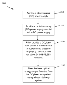
[0037] FIG. 2 is a flowchart of an embodiment of outputting laser
optical energy from a
CO2 dental laser system, in accordance with aspects of the present invention.
DETAILED DESCRIPTION OF PREFERRED EMBODIMENTS
[0038] Hereinafter, aspects of the present invention will be
described by explaining
illustrative embodiments in accordance therewith, with reference to the
attached drawings.
While describing these embodiments, detailed descriptions of well-known items,
functions, or
configurations are typically omitted for conciseness.
[0039] It will be understood that when an element is referred to as
being "on" or
"connected" or "coupled" to another element, it can be directly on or
connected or coupled to
the other element or intervening elements can be present. In contrast, when an
element is
referred to as being "directly on" or "directly connected" or "directly
coupled" to another element,
there are no intervening elements present. Other words used to describe the
relationship
between elements should be
6
CA 02769448 2012-01-27
WO 2011/014802
PCT/US2010/043968
interpreted in a like fashion (e.g., "between" versus "directly between,"
"adjacent"
versus "directly adjacent," etc.).
[0040] The terminology used herein is for the purpose of describing
particular
embodiments only and is not intended to be limiting of the invention. As used
herein,
the singular forms "a," "an" and "the" are intended to include the plural
forms as well,
unless the context clearly indicates otherwise. It will be further understood
that the
terms "comprises," "comprising," "includes" and/or "including," when used
herein,
specify the presence of stated features, steps, operations, elements, and/or
components, but do not preclude the presence or addition of one or more other
features, steps, operations, elements, components, and/or groups thereof.
[0041] With respect to dental laser systems, the wavelength with the
highest
absorption in hydroxyapatite has been determined to be in the 9.3 to 9.6
pmeter
range and the thermal relaxation time of hydroxyapatite to be a maximum of 2
pseconds at 9.3 to 9.6 pm wavelength range. Therefore, the ideal pulse
parameters
for removing the hydroxyapatite appear to be 9.3 to 9.6 pmeter energy in a
less than
50 psecond format. In accordance with the preferred embodiment, a laser is
provided that produces a beam having pulse parameters for removing
hydroxyapatite using 9.3 to 9.6 pm wavelength energy in a less than 50 psecond
format.
[0042] The 9.3 to 9.6 pm energy is typically produced using a CO2 laser
with a
laser gas mixture of 12C(180)2,
wavelength selective resonator optics, more
expensive inter-cavity wavelength devices, or a combination of the three. In
accordance with the present invention, the 50 psecond pulses are produced with
a
fast pulse rise and fall time, which is effected by laser gas pressure. In
order to
produce pulses of less than or equal to 50 pseconds in length, with gas
pressure of
at least about 260 Torr (or about 34,663 Pa).
[0043] According to preferred embodiment, a CO2 gas laser, in either
a
waveguide or slab resonator format, filled with gas that is in a range of
about 260
Torr to 600 Torr (or about 34,700 - 80,000 Pa), which is RF excited for use in
all
dental applications. A range of about 260 to 600 Torr (or about 34,700 -
80,000 Pa)
7
CA 02769448 2012-01-27
WO 2011/014802
PCT/US2010/043968
may be preferable in many dental applications. Since waveguide and slab
resonators are generally known in the art, they are not discussed in detail
herein.
[0044] In some embodiments, the pressure can be in a range of about
280 -
550 Torr (or about 37,330 ¨ 73,327 Pa), about 300-500 Torr (or about 39,996 ¨
66,661 Pa), about 320 - 450 Torr (or about 42,663 - 59,995 Pa), about 340 -
400
Torr (or about 45,329 ¨ 53,328 Pa), as examples.
[0045] The laser can be operated in CW or pulsed mode for cutting and
drilling applications, respectively. DC and RF power supplies are configured
to aid in
low power CW operation, while supporting high peak power pulse operation. The
laser output is coupled to a beam delivery system to deliver the optical
energy to the
patient. The laser provides the 9.3 to 9.6 pm energy wavelength, with a fast
pulse
rise and fall time (e.g., not more than about 50 pseconds, and preferably not
more
than 20 psecond), sealed off operation, high repetition rates in a small
reliable
package.
[0046] FIG. 1 shows an embodiment of a dental laser system 100 according to
aspects of the present invention. In the embodiment of FIG. 1, a DC power
supply
10 is provided that rectifies as AC input power (not shown). In the preferred
embodiment, the DC power supply 10 is comprised of a continuous wave (CW) DC
section 12 and a pulsed DC section 14. The DC section 12 is sized to run the
laser
for CW applications, such as soft tissue cutting, and the peak power DC
section 14
supplies the peak energy for pulsing applications, such as hard tissue
modification.
[0047] Item 20 is a radio frequency (RF) power supply for the
conversion of
the DC energy to RF energy in the 40 to 125 MHZ range. Item 30 is a CO2 laser
with
the RF energy as an input and 9.3 to 9.6 pmeter optical energy as an output,
via an
output coupler 32. And item 40 is a beam delivery apparatus, which delivers
the
optical energy from the laser to item 50, which represents a patient's mouth.
[0048] CO2 laser 30 in this embodiment includes a rear mirror 34 and
a laser
discharge area 36. The mirror 34 directs optical energy through the laser
discharge
area 36. The output coupler 32 couples the beam out of the laser. In this case
the
laser is a gas laser, so the output coupler couples the beam out of the laser
without
allowing the laser gas out. The CO2 laser 30 also includes a laser gas
pressure
8
CA 02769448 2012-01-27
WO 2011/014802
PCT/US2010/043968
vessel 38 that is filled with a gas at a pressure in a range of about 260 to
about 600
Torr (or about 34,700 - 80,000 Pa).
[0049] The output laser energy is provided to the beam delivery
apparatus 40,
where it can then be directed to a target, such as a patient's mouth. In this
embodiment, the beam delivery apparatus 40 can include a combination of flat
or
curved mirrors configured to steer optical energy output from the CO2 laser.
[0050] In this exemplary configuration, the dental laser system 100
can
operate at both low power CW operation, e.g., < 10 watts, for the cutting of
gums
and oral tissue, and high peak power pulsing operation, e.g., > 5mJ pulse
energy at
1 to 50 pseconds pulse widths up to 10 KHz. The CO2 laser 30 can operate at
wavelengths between 9 and 11 pm. The laser system 100 preferably provides high
peak power pulsing operation at the ideal absorption wavelength for the
hydroxyapatite in dental hard tissues. The pulse widths and pulse energy are
ideally
suited to ablate hydroxyapatite, leaving very little residual heat in the
tooth to
damage the pulp even up to 10 KHz in operation.
[0051] FIG. 2 is an embodiment of a method of outputting laser
optical energy
from a CO2 dental laser system. The method 200 includes providing a direct
current
(DC) power supply in step 210, providing a radio frequency (RF) power supply
coupled to the DC power supply in step 220, filling a CO2 laser with gas at a
pressure
in a predetermined pressure range (e.g., about 260 to 600 Torr (or about
34,700 -
80,000 Pa)) in step 230, and steering the laser optical energy output from the
from
the CO2 laser to a patient using a beam delivery system 240.
[0052] While the foregoing has described what are considered to be
the best
mode and/or other preferred embodiments, it is understood that various
modifications can be made therein and that the invention or inventions may be
implemented in various forms and embodiments, and that they may be applied in
numerous applications, only some of which have been described herein. For
example, it is possible that the described laser and laser system could be
used in
other (non-dental) applications. It is intended by the following claims to
claim that
which is literally described and all equivalents thereto, including all
modifications and
variations that fall within the scope of each claim.
9