Note: Descriptions are shown in the official language in which they were submitted.
CA 02769534 2012-01-27
WO 2011/014537 PCT/US2010/043489
Atty Docket: 7247WO01
HFFS PACKAGING METHOD AND APPARATUS FOR REFRIGERATED
DOUGH
FIELD OF THE INVENTION
The invention pertains to the art of packaging and, more particularly, to
packaging
refrigerated dough in a horizontal form, fill and seal (HFFS) system utilizing
direct
vertical product loading.
BACKGROUND OF THE INVENTION
It is common to package a refrigerated dough product in a canister of a fixed
volume formed from composite paperboard which is spirally wound into a
cylinder, with
the refrigerated dough product being further proofed in the canister. In one
known system,
a packer is used to cut hexagonal shaped dough pieces, such as biscuits, from
a sheet of
dough and direct the dough pieces into respective canisters traveling below
the packer.
This overall process can be used to effectively stack multiple dough pieces,
such as 4-10
biscuits, in a single, substantially continuously indexed container at a high
rate. However,
packaging products in cardboard is actually, relatively expensive and, at
least in
connection with products having a small profit margin, can be cost
prohibitive.
Mainly because of cost efficiencies and packaging versatility, vertical and
horizontal form, fill and seal packaging systems have become increasingly
popular,
particularly in the food industry. While vertical form, fill and seal systems
have mainly
been limited for use in connection with making sealed bags, such as potato
chip and other
types of snack bags, horizontal form, fill and seal packaging systems are
considered to be
much more versatile, yet scarcely employed. By way of example, it is known to
utilize a
horizontal form, fill and seal (HFFS) system to create product cavities or
pouches in a
lower film, fill the pouches with frozen dough products and seal the products
in the
pouches with an upper film. Prior to fully sealing the pouches, a vacuum is
typically
drawn in order to reduce the available headspace of the package. Although
evacuating the
headspace is appropriate for frozen dough products, employing a vacuum on a
refrigerated
dough product would inherently destroy nucleation sites for leavener in the
dough and,
consequently, the overall product.
1
CA 02769534 2012-01-27
WO 2011/014537 PCT/US2010/043489
Although the above discussion exemplifies disadvantages with utilizing an HFFS
system with refrigerated dough products, HFFS systems have been employed in
packaging
other types of food products, including a single package containing a meal of
meat, cheese
and crackers. At least one major problem associated with the known uses of
HFFS systems
in packing refrigerated products is that the products are fully formed at one
process
location and loaded into the package at another process location in a non-
continuous
fashion. Using the product example given above, each of the meat, cheese and
cracker
products are formed at distinct locations and often shipped separately to a
packing plant.
There, a receiving package is formed and directed to distinct operating
stations for
loading. After each product loading has been completed, the package can be
sealed.
Certainly, the many advantages of utilizing HFFS systems make them enticing to
employ. However, these advantages have mostly been outweighed by their
disadvantages,
at least with respect to particular products and loading constrictions. In
particular, there
has not heretofore been proposed a way to integrate a HFFS system to be used
in
efficiently mass producing and concurrently, vertically packaging refrigerated
dough
products. To this end, there is seen to still exist a need for new ways of
packaging
refrigerated dough products that can take advantage of the benefits of HFFS
systems while
avoiding known system drawbacks.
SUMMARY OF THE INVENTION
The invention is directed to a method for packaging refrigerated dough
products
utilizing a horizontal form, fill and seal (HFFS) system wherein the products
are cut and
directly stacked into flexible pouches. According to the invention, the
packaging method
includes creating product receiving cavities in a lower film, directly
vertically stacking
products in the product receiving cavities and then sealing the vertically
stacked products
in the cavities with an upper film to form product pouches. In one embodiment
of the
invention, a product fill station of the HFFS system is advantageously defined
by a
hexagonal or other shaped packer including a stamping unit for both cutting
and directly
vertically stacking the products in one operation. In another embodiment, a
vertical lift
and feed mechanism is employed to vertically stack the products in the
receiving cavities.
Additional objects, features and advantages of the invention will become more
readily apparent from the following detailed description when taken in
conjunction with
2
CA 02769534 2012-01-27
WO 2011/014537 PCT/US2010/043489
the drawings wherein like reference numerals refer to corresponding parts in
the several
views.
BRIEF DESCRIPTION OF THE DRAWINGS
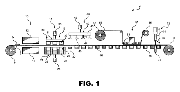
Figure 1 schematically illustrates a horizontal form, fill and seal (HFFS)
system in
accordance with the invention.
Figure 2A is a top view of a packaging strip produced in accordance with the
invention.
Figure 2B is side view of the packaging strip of Figure 2A.
Figure 3A is a top view of a single package cut from the packaging strip of
Figure
2A.
Figure 3B is a side view of the package of Figure 3A.
Figure 4 is a partial perspective view of a shaped packer employed in the HFFS
system of Figure 1.
DETAILED DESCRIPTION OF EMBODIMENTS
With initial reference to Figure 1, a horizontal form, fill and seal (HFFS)
system
employed in connection with the packaging method of the invention is generally
indicated
at 2. As shown, system 2 has associated therewith a first or lower film 5
which runs from
a payout reel 7 in the direction of arrow A to a take-up reel 8. As will
become more fully
evident below, the majority of film 5 is used in connection with packaging
products in
accordance with the invention and take-up reel 8 receives the left over or
scrap film. In
one form of the invention, take-up reel 8 merely receives lateral edge
portions of lower
film 5, such as an inch (approximately 2.54 cm) or less of either side of film
5 while the
remainder of the film 5 is employed in the final package. In any case, lower
film 5 is first
directed to a heating station 10 and is directed between upper and lower
heating units 12
and 13. In general, heating station 10 can employ various types of heater
units 12, 13
known in the art, such as radiant and/or convection heaters. Basically, it is
simply desired
to heat lower film 5 for delivery to thermoforming station 18. In
thermoforming station
18, a thermoforming unit 19 is employed to produce product cavities 20 in
lower film 5.
To this end, thermoforming unit 19 includes a lower cavity mold 21 having a
main body
22 formed with recessed cavities 23. A linear actuator 24 is connected to main
body 22
and designed to vertically shift main body 22 during the forming of product
cavities 20.
3
CA 02769534 2012-01-27
WO 2011/014537 PCT/US2010/043489
For use in connection with the forming process, fluid communication lines,
such as that
indicated at 25, extend through main body 22 to recessed cavities 23. In
conjunction with
lower cavity mold 21, thermoforming unit 19 includes an upper cavity mold 30
which also
includes a main body 31 from which extend various projection molds 32 that
conform to
recessed cavities 23. Ina manner similar to lower cavity mold 21, upper cavity
mold 30 is
connected to a linear actuator 33 used to vertically shift upper cavity mold
30 during a
thermoforming operation.
In general, thermoforming devices such as that employed in connection with
forming station 18 are widely known in the art such that details thereof need
not be
presented here. However, for the sake of completeness, it should at least be
understood
that the function of forming station 18 is to receive heated lower film 5
between lower
cavity mold 21 and upper cavity mold 30, at which time the movement of lower
film 5 is
temporarily stopped and projection molds 32 are mated with recessed cavities
23 in order
to reshape lower film 5 to include product cavities 20. To aid in this shaping
operation,
fluid communication lines 25 can be hooked to a vacuum source (not shown) in
order to
draw lower film 5 against recessed cavities 23, as well as to subsequently
apply a positive
pressure to aid in removing the formed product cavities 20 from lower cavity
mold 21
after the thermoforming process is complete.
Once product cavities 20 are formed in lower film 5, lower film 5 advances to
a
loading or filling station generally indicated at 40. At this point, it should
be noted that the
invention is particularly concerned with employing a vertical loading system
for filling
product cavities 20. To this end, although filling station 40 can take various
forms without
departing from the invention, filling station 40 includes a vertical loading
unit, such as
vertical loading unit 42 including a platform 43 from which extend various
loading arms
44 used to transport products, such as that indicated at 46, into the
individual product
cavities 20. As the vertical loading is an important part of the invention,
further details
thereof will be presented below after discussing other overall aspect of HFFS
system 2.
After products 46 are loaded into product cavities 20, lower film 5 is
advanced to a
sealing station 52. In general, the invention is not concerned with the
specific manner in
which products 46 are sealed within product cavities 20. However, as is widely
known in
connection with standard HFFS systems, a second or upper film 56 is drawn from
a payout
reel 57. After following various guide rollers 63 to sealing station 52, the
remainder of
upper film 56 is directed to a take-up reel 65. At sealing station 52, upper
film 56 is sealed
4
CA 02769534 2012-01-27
WO 2011/014537 PCT/US2010/043489
to lower film 5 across product cavities 20 in order to create an overall
product package in
the form of a flexible pouch as indicated at 68. Figure 2A and 2B illustrate a
product strip
69, shown constituted by adjacent, connected packages 68 each containing two
stacked
products 46, as present in HFFS system 2 after sealing station 52. Thereafter,
in referring
back to Figure 1, package 68 is directed to a cutter station 72 wherein a
blade element 73
is shifted vertically through the use of a linear actuator 74 against an anvil
member 75 in
order to cut each package 68 from the overall web defined by the mated lower
film 5 and
upper film 56. After cutter station 72, each package takes the form shown in
Figures 3A
and 3B. At this point, it should be understood that the exact shape of package
68, as well
as product 46, can vary from that shown in these figures. Instead, it is only
important that
each product receiving cavity 20 is formed, filled and sealed in an HFFS
system and that
products 46 are vertically loaded.
As indicated above, filling station 40 can take various forms without
departing
from the invention. In a simple form, vertical loading unit 42 can be
constituted by a robot
unit which can be shifted into or out of the page of Figure 1 to pick-up
products 46, such
as through the use of a suction system (not shown), and then shifts vertically
over product
cavities 20 prior to vertically depositing products 46 into cavities 20. In a
more advanced
form employed in connection with mass producing packages 68, vertically
loading unit 42
is constituted by a hexagonal or other product shaped packer assembly for both
cutting and
directly vertically stacking refrigerated dough products 46. For details of
this
embodiment, reference is made to Figure 4 which illustrates a shaped packer
100
employed in HFFS system 2. As shown, a series of adjacent product strips 69
are
conveyed in a first direction X and under a transport cutter plate 102. A
sheet 104 of
dough is directed along a conveyor 108, beneath a roller 110 and upon
transport cutter
plate 102 that moves in a second direction Y which is angled, more
specifically
perpendicular in the embodiment shown, relative to the first direction X.
Transport cutter
plate 102 is shown to take a generally honeycomb form, defining various
openings 112
established by interconnected dough cutting edges 116 arranged in a hexagonal
shape.
This shape is desirable as it virtually eliminates any residual dough, except
perhaps at the
lateral edges of dough sheet 104. However, other shapes, such as circular or
various
polygon-shaped openings, could be employed. In any case, roller 110 forces the
dough
sheet 104 into openings 112 to create various products 46 prior to packer 100
as clearly
shown in this figure. Upon reaching packer 100 (shown as a stamping unit),
vertical
5
CA 02769534 2012-01-27
WO 2011/014537 PCT/US2010/043489
shifting of loading unit 42 causes loading arms 44, which are aligned with
respective
openings 112, to push or stamp products 46 directly vertically into respective
ones of the
product cavities 20. Thereafter, the products 46 will be re-directed to travel
in the first
direction with product strips 69.
Depending on various factors, such as the size of the individual products 46,
the
dimensions of transport cutter plate 102, the number of adjacent product
strips 69 and the
indexing time for first film 5 (which is basically governed by the required
formation time
at forming station 18), the travel speed for dough sheet 104 on transport
cutter plate 102
and the operation cycle for loading unit 42 can be readily established to
provide for a
generally continuous production line. By way of example, a hexagonal packer
designed to
generate eighty products during each cycle utilizing a cutter plate having 204
openings is
operated as an intermittent machine with a consistent cycle even though dough
is fed to
the packer unit at a constant speed. In this instance, accommodations are made
for the
periodic accumulation of dough between the sheeting line and the packer 100.
This
loading system is used with a HFFS system which is 24" wide and has a 24"
index
distance. The HFFS system has a dwell time of approximately 60% of a cycle for
the
thermoforming operation and requires approximately 40% of the cycle to advance
the
film. At thirty cycles per minute, one cycle would occur in two seconds,
requiring 1.2
seconds to form pouches and 0.8 seconds to advance the film in preparation of
the next
cycle. In a main embodiment, the pouches are loaded during the dwell period.
Certainly,
maximizing the index distance will increase the output. That is, additional
pouches can be
filled during each stroke of the loader unit by increasing the width and/or
length of the
cutter bar in combination with adjusting the number of pouches presented for
loading in
each cycle.
Although described with reference to certain embodiments of the invention, it
should be readily understood that various changes and/or modifications can be
made to the
invention without departing from the spirit thereof. For instance, the shape
of the
products, the configuration of the packaging and the number of vertically
arranged
products can be altered. In particular, a generally peanut-shaped dual product
package
having adjoining cavities can be advantageously employed with minimal product
spacing,
or a twin stack/single cavity packaging can be established. In addition, other
alternatives
could also be employed to increase production rate, such as directing a
second, offset array
6
CA 02769534 2012-01-27
WO 2011/014537 PCT/US2010/043489
of product pouches to the loading station. In general, the invention is only
intended to be
limited by the scope of the following claims.
7