Language selection

Search

Patent 2769639 Summary

Third-party information liability

Some of the information on this Web page has been provided by external sources. The Government of Canada is not responsible for the accuracy, reliability or currency of the information supplied by external sources. Users wishing to rely upon this information should consult directly with the source of the information. Content provided by external sources is not subject to official languages, privacy and accessibility requirements.

Claims and Abstract availability

Any discrepancies in the text and image of the Claims and Abstract are due to differing posting times. Text of the Claims and Abstract are posted:

  • At the time the application is open to public inspection;
  • At the time of issue of the patent (grant).
(12) Patent: (11) CA 2769639
(54) English Title: CARRIAGE MASSAGER WITH PROGRAMMABLE TRAVEL
(54) French Title: DISPOSITIF DE MASSAGE A CHARIOT AVEC DEPLACEMENT PROGRAMMABLE
Status: Granted
Bibliographic Data
(51) International Patent Classification (IPC):
  • A61H 7/00 (2006.01)
(72) Inventors :
  • HARRISON-MEYER, ELIZABETH (United States of America)
  • LEV, MORDECHAI (United States of America)
(73) Owners :
  • FKA DISTRIBUTING CO., LLC (United States of America)
(71) Applicants :
  • FKA DISTRIBUTING CO. D/B/A HOMEDICS, INC. (United States of America)
(74) Agent: BORDEN LADNER GERVAIS LLP
(74) Associate agent:
(45) Issued: 2018-06-12
(86) PCT Filing Date: 2010-07-27
(87) Open to Public Inspection: 2011-02-03
Examination requested: 2015-07-09
Availability of licence: N/A
(25) Language of filing: English

Patent Cooperation Treaty (PCT): Yes
(86) PCT Filing Number: PCT/US2010/043371
(87) International Publication Number: WO2011/014501
(85) National Entry: 2012-01-30

(30) Application Priority Data:
Application No. Country/Territory Date
61/229,865 United States of America 2009-07-30

Abstracts

English Abstract

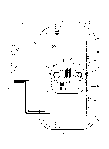
A body massager has a housing, with a carriage oriented in the housing and cooperating with the housing for longitudinal translation in the housing. A massage member is provided on the carriage. A motor is in operable connection with the housing and the carriage for driving the carriage along the housing. A controller is in operable communication with the motor for controlling the translation of the carriage. The controller has a programmable memory feature for storing a position of the carriage relative to the housing for limiting a range of translation of the carriage along the housing.


French Abstract

L'invention porte sur un dispositif de massage du corps, qui a un boîtier, avec un chariot orienté dans le boîtier et coopérant avec le boîtier pour une translation longitudinale dans le boîtier. Un élément de massage est disposé sur le chariot. Un moteur est en liaison fonctionnelle avec le boîtier et le chariot pour entraîner le chariot le long du boîtier. Un dispositif de commande est en communication fonctionnelle avec le moteur pour commander la translation du chariot. Le dispositif de commande a une caractéristique de mémoire programmable pour stocker une position du chariot par rapport au boîtier pour limiter une plage de translation du chariot le long du boîtier.

Claims

Note: Claims are shown in the official language in which they were submitted.


CLAIMS:
1. A body massager comprising:
a housing;
a carriage oriented in the housing and cooperating with the housing for
longitudinal
translation in the housing;
at least one massage member provided on the carriage;
a motor in operable connection with the housing and the carriage for driving
the
carriage along the housing;
a controller in operable communication with the motor for controlling the
translation
of the carriage, the controller having a programmable memory feature for
storing a position of
the carriage relative to the housing for limiting a range of translation of
the carriage along the
housing, the programmable memory feature comprising a timer; and
a pair of limit switches mounted to the housing in operable communication with
the
controller for detecting a range of translation of the carriage in the
housing;
wherein the housing is further defined as a backrest;
wherein the pair of limit switches are further defined as an upper limit
switch provided
at an upper limit of the range of travel of the carriage in the housing, and
as a lower limit
switch provided at a lower limit of the range of travel of the carriage in the
housing;
wherein the programmable memory feature stores a position between the pair of
limit
switches; and
wherein the programmable memory feature stores the position of the carriage
for
limiting the range of translation between the stored position and the lower
limit switch.
2. The body massager of claim 1 further comprising a mechanical switch for
inputting
the stored position manually.
3. The body massager of claim 1 wherein the controller reverses the
rotation of the motor
in response to a signal from one of the pair of limit switches to reverse the
translation of the
carriage.
6

4. The body massager of claim 1 wherein the controller reverses the
rotation of the motor
in response to the programmable memory feature to reverse the translation of
the carriage.
5. The body massager of claim 1 wherein the controller is configured for:
driving the carriage along the range of travel in a first direction;
monitoring a position of the carriage during translation along the range of
travel;
receiving an input of a desired limit to the range of travel; and
storing a position corresponding to the input of the desired limit.
6. The body massager of claim 5 wherein the controller is further
configured for
reversing travel of the carriage for travel in a second direction upon
receiving the input of the
stored position.
7. The body massager of claim 5 wherein the controller is further
configured for
reversing travel of the carriage in a second direction upon reaching a limit
to the range of
travel.
8. The body massager of claim 5 wherein the controller is further
configured for
reversing travel of the carriage in the first direction upon reaching the
stored position.
9. The body massager of claim 5 wherein the controller is further
configured for:
determining if a maximum position function is on; and
if the maximum position function is off, translating the carriage without the
stored
position as a limit to the range of travel.
10. The body massager of claim 5 wherein the controller is further
configured for:
determining if a maximum position function is on; and
if the maximum position function is on, translating the carriage with the
stored
position as a limit to the range of travel.
7

11. The body massager of claim 5 wherein the controller is further
configured for:
determining if a maximum position function is on; and
if the maximum position function is on, monitoring the position of the
carriage.
12. The body massager of claim 5 wherein the controller is further
configured for:
determining if a maximum position function is on;
if the maximum position function is on, determining if the carriage has
reached the
stored position; and
if the carriage has reached the stored position, reversing the translation of
the carriage.
13. The body massager of claim 5 wherein the controller is further
configured for:
determining if a maximum position function is on;
if the maximum position function is on, determining if the carriage has
reached the
stored position; and
if the carriage has not reached the stored position, monitoring the position
of the
carriage.
8

Description

Note: Descriptions are shown in the official language in which they were submitted.


CA 2769639 2017-03-22
CARRIAGE MASSAGER WITH PROGRAMMABLE TRAVEL
TECHNICAL FIELD
Various embodiments relate to body massagers.
BRIEF DESCRIPTION OF THE DRAWINGS
FIGURE 1 is a schematic view of a body massager according to an embodiment;
and
FIGURE 2 is a flowchart for a method for controlling the massager of Figure I.
DETAILED DESCRIPTION
As required, detailed embodiments of the present invention are disclosed
herein; however,
it is to be understood that the disclosed embodiments are merely exemplary of
the invention that
may be embodied in various and alternative forms. The figures are not
necessarily to scale; some
features may be exaggerated or minimized to show details of particular
components. Therefore,
specific structural and functional details disclosed herein are not to he
interpreted as limiting, but
merely
- 1 -

CA 2769639 2017-03-22
as a representative basis for teaching one skilled in the art to variously
employ the present
invention.
Referring now to Figure 1, a body massager is illustrated according to an
embodiment and
is referenced generally by numeral 10. The body massager includes a backrest
12. The body
massager 10 may also include a seat support (not shown). The internal
assemblies of the backrest 12
are collectively retained within a flexible cover (not shown). Massage effects
provided by the body
massager 10 include a rolling massage effect and a kneading massage effect
provided in the
backrest 12, which is operable to provide the massage effects longitudinally
along the length of the
backrest 12.
The backrest 12 is sized to be received upon a backrest of a conventional
chair. The body
massager 10 is portable due to its compact size and light weight so that the
user may place the body
massager 10 upon a conventional chair for receiving a massage when seated upon
the chair. The
backrest 12 includes a height and a width corresponding to the conventional
chair and has a
thickness that is adequate for housing a massage assembly while avoiding
disruption of comfort and
support provided by the underlying chair.
The backrest 12 includes a backrest surface for receiving and supporting the
back of a user.
The backrest 12 includes a housing 14, which may be a single piece, or
multiple pieces for retaining
a massage assembly 16 within the housing 14. The massage assembly 16 of the
backrest 12 imparts
massage effects to the backrest surface.
The massage assembly 16 includes a carriage 18 which cooperates with the
housing 14 for
limited longitudinal translation within the backrest 12. The housing 14
includes a longitudinal guide
20 for cooperating with the carriage 18. A suitable guide is illustrated and
described in greater detail
in U.S. Patent No. 7,470,242 B2.
- 2 -

CA 2769639 2017-03-22
The massage assembly 16 may include a first motor 22 mounted to the carriage
18 for
driving a transmission 24. The transmission 24 may include an output gear 26,
which is engaged
with a gear rack 28 that is mounted to the housing 14. Operation of the first
motor 22 provides
rotation to the output gear 26 thereby driving the carriage 18 along the guide
20. Suitable
transmissions are disclosed in Ferber et al. U.S. Patent No. 7,128,721 B2; and
Ferber et al. U.S.
Patent No. 7,470,242 B2.
The carriage 18 may also include a pair of massage members 30 for providing a
rolling
massage effect as the carriage 18 is translated along the guide 20. The
massage members 30 may
each include a pair of massage nodes 32, 34. The massage members 30 may be
rotatably connected
to the carriage 18 and driven to counter-rotate for providing a rotary
kneading massage effect. The
massage members 30 may each be driven by the first motor 22 as disclosed in
the Ferber et al. U.S.
7,128,721 B2 patent. Alternatively, a second motor 36 may be provided on the
carriage 18 for
driving the massage members 30 independent of the translation of the carriage
18, as disclosed in
the U.S. 7,470,242 B2 patent.
The motors 22, 36 are each connected to and controlled by a controller 38. The
massager 10
includes a manual remote controller 40 with mechanical switches, such as push
buttons 42, in
communication with the controller 38. The controller 38 may be oriented within
the housing 14 of
the massager 10, or within the remote controller 40.
The massager 10 also includes a pair of limit switches 44, 46 in connection
with the
controller 38. The upper limit switch 44 is located at an upper range of the
travel of the carriage 18.
The lower limit switch 46 is located at a lower range of travel of the
carriage 18. Upon the carriage
18 reaching one of the limits to the range of travel, the carriage 18 engages
one of the limit switches
44, 46 thereby signaling the end of travel position to the controller 38. In
response to the signal, the
controller 38 reverses rotation of the first motor 22 thereby reversing the
direction of travel of the
carriage 18. Of course, additional limit switches may be employed for
- 3 -

CA 2769639 2017-03-22
limiting travel of the carriage 18 to various regions as disclosed in the
Ferber et al. 7,128,721 B2
patent.
The maximum range of travel of the carriage 18 is labeled by zones A and C in
Figure 1.
Typically, the range of travel is designed for users of varying height thereby
resulting in a range of
travel that may exceed a height of a given user. When a user of a prior art
massager has a body part
surface, such as a back surface, that does not span the length of the range of
travel, the user may
experience a delay in the upper range of travel wherein the massage members 30
disengage from
the user's back as the carriage 18 continues to travel to the extent of the
range of travel and then
subsequently return. The range of travel of the carriage 18 depicted, is
customizable to provide a
user selected range of travel. This user selected range of travel is
maintained by a programmable
memory feature in the controller 38.
Referring now to Figures 1 and 2, the operation of the massage assembly 16 is
illustrated
and described. At block 48, the massager 10 is powered on with the massage
assembly 16 on
standby, and the controller 38 memory assesses preliminary data. At block 50,
the controller 38
identifies the position of the carriage 18 based on the memory. For example,
the controller 38
includes a timer, which measures the length of travel of the carriage 18 by a
function of time. If the
carriage 18 was left at an intermediate position within the range, that
position is determined by the
remaining time on the timer. Alternatively, the position of the carriage 18
may be identified at block
50 by a signal sent to the controller 38 by one of the limit switches 44, 46.
As the carriage 18
translates along the guide 20, thereby providing the massage effect, the timer
monitors the position
of the carriage 18 as a function of time.
At decision block 52, the controller 38 determines whether a user has pressed
one of the
push buttons 42 associated with storing a position for limiting the range of
travel of the carriage 18.
For example, the user may have pressed the button 42 for storing the position
at intermediate
location B in Figure 1. If so, position B is stored at block 54 in Figure 2.
If the user has not pressed
the store position button 42, then block 54 is skipped. If the carriage 18 is
traveling in an upward
direction, for example from position C to position A in Figure 1, and the
button 42 is pressed at
- 4 -

CA 02769639 2012-01-30
WO 2011/014501 PCT/US2010/043371
position B, the controller 38 can reverse the direction of the carriage 18 to
prevent the
carriage 18 from traveling in the region from B to A, which would be outside
the
desired limit selected by the user.
At decision block 56, the controller 38 determines if the maximum
position function is on. If not, the massager 10 operates at a normal setting
at block
60, wherein the carriage 18 travels from position A to position C and reverses

direction each time it contacts one of the limit switches 44, 46. If the
maximum
selected position function is on, the carriage 18 travels to the lower limit C
at limit
switch 46 at which point the carriage 18 reverses its direction. At decision
block 58,
the timer monitors the position of the carriage 18 until it reaches the
maximum
selected position indicated by region B. If the maximum selected position is
reached,
the carriage 18 reverses direction and returns back towards the lower limit in
block 62.
If the maximum selected position has not yet been reached, the carriage 18
continues
to travel upward.
Although a timer has been described, the invention contemplates that
the massager 10 may employ any programmable memory feature, such as a counter
for measuring rotations of the motor 22, Hall-Effect sensors for measuring
pulses of
the motor 22, an encoder for measuring the position of the carriage 18, a
potentiometer
for measuring the distance of the carriage 18, or any suitable sensor or
method for
monitoring the position of the carriage 18 and storing the desired limit to
the range of
travel.
While embodiments of the invention have been illustrated and
described, it is not intended that these embodiments illustrate and describe
all possible
forms of the invention. Rather, the words used in the specification are words
of
description rather than limitation, and it is understood that various changes
may be
made without departing from the spirit and scope of the invention.
Additionally,
features of various implementing embodiments may be combined to form further
embodiments of the invention.
-5-

Representative Drawing
A single figure which represents the drawing illustrating the invention.
Administrative Status

For a clearer understanding of the status of the application/patent presented on this page, the site Disclaimer , as well as the definitions for Patent , Administrative Status , Maintenance Fee  and Payment History  should be consulted.

Administrative Status

Title Date
Forecasted Issue Date 2018-06-12
(86) PCT Filing Date 2010-07-27
(87) PCT Publication Date 2011-02-03
(85) National Entry 2012-01-30
Examination Requested 2015-07-09
(45) Issued 2018-06-12

Abandonment History

There is no abandonment history.

Maintenance Fee

Last Payment of $263.14 was received on 2023-07-21


 Upcoming maintenance fee amounts

Description Date Amount
Next Payment if standard fee 2024-07-29 $347.00
Next Payment if small entity fee 2024-07-29 $125.00

Note : If the full payment has not been received on or before the date indicated, a further fee may be required which may be one of the following

  • the reinstatement fee;
  • the late payment fee; or
  • additional fee to reverse deemed expiry.

Patent fees are adjusted on the 1st of January every year. The amounts above are the current amounts if received by December 31 of the current year.
Please refer to the CIPO Patent Fees web page to see all current fee amounts.

Payment History

Fee Type Anniversary Year Due Date Amount Paid Paid Date
Application Fee $400.00 2012-01-30
Registration of a document - section 124 $100.00 2012-04-26
Maintenance Fee - Application - New Act 2 2012-07-27 $100.00 2012-07-18
Registration of a document - section 124 $100.00 2012-10-31
Maintenance Fee - Application - New Act 3 2013-07-29 $100.00 2013-07-19
Maintenance Fee - Application - New Act 4 2014-07-28 $100.00 2014-07-25
Registration of a document - section 124 $100.00 2014-11-13
Maintenance Fee - Application - New Act 5 2015-07-27 $200.00 2015-07-03
Request for Examination $800.00 2015-07-09
Maintenance Fee - Application - New Act 6 2016-07-27 $200.00 2016-07-21
Maintenance Fee - Application - New Act 7 2017-07-27 $200.00 2017-07-21
Final Fee $300.00 2018-04-25
Maintenance Fee - Patent - New Act 8 2018-07-27 $200.00 2018-07-23
Maintenance Fee - Patent - New Act 9 2019-07-29 $200.00 2019-07-19
Maintenance Fee - Patent - New Act 10 2020-07-27 $250.00 2020-07-17
Maintenance Fee - Patent - New Act 11 2021-07-27 $255.00 2021-07-23
Maintenance Fee - Patent - New Act 12 2022-07-27 $254.49 2022-07-22
Maintenance Fee - Patent - New Act 13 2023-07-27 $263.14 2023-07-21
Owners on Record

Note: Records showing the ownership history in alphabetical order.

Current Owners on Record
FKA DISTRIBUTING CO., LLC
Past Owners on Record
FKA DISTRIBUTING CO. D/B/A HOMEDICS, INC.
Past Owners that do not appear in the "Owners on Record" listing will appear in other documentation within the application.
Documents

To view selected files, please enter reCAPTCHA code :


To view images, click a link in the Document Description column. To download the documents, select one or more checkboxes in the first column and then click the "Download Selected in PDF format (Zip Archive)" or the "Download Selected as Single PDF" button.

List of published and non-published patent-specific documents on the CPD .

If you have any difficulty accessing content, you can call the Client Service Centre at 1-866-997-1936 or send them an e-mail at CIPO Client Service Centre.


Document
Description 
Date
(yyyy-mm-dd) 
Number of pages   Size of Image (KB) 
Abstract 2012-01-30 2 70
Claims 2012-01-30 5 146
Drawings 2012-01-30 2 33
Description 2012-01-30 5 227
Representative Drawing 2012-01-30 1 18
Cover Page 2012-04-10 2 44
Examiner Requisition 2017-05-16 3 210
Amendment 2017-11-15 9 333
Claims 2017-11-15 3 91
Final Fee 2018-04-25 1 34
Representative Drawing 2018-05-11 1 8
Cover Page 2018-05-11 1 38
PCT 2012-01-30 14 783
Assignment 2012-01-30 4 95
Request for Examination 2015-07-09 1 37
Assignment 2012-04-26 4 242
Assignment 2012-10-31 23 819
Assignment 2012-10-30 25 915
Correspondence 2012-11-15 1 23
Assignment 2014-11-13 9 320
Examiner Requisition 2016-09-22 5 230
Amendment 2017-03-22 22 721
Claims 2017-03-22 3 82
Description 2017-03-22 5 175