Note: Descriptions are shown in the official language in which they were submitted.
CA 02769672 2012-01-31
W02011/018211 1 PCT/EP2010/004897
Transport container
The invention relates to a transport container consisting of a
bottom part and of side walls that project perpendicular from
it, having molded-in parts provided in the bottom region, for
accommodating the goods to be transported, with precise fit, and
for further support of these goods above the bottom region.
The formed-in parts can be provided in an insert that is laid
into the transport container. Or the formed-in parts are an
integral component of the bottom itself. The term "bottom part"
is selected to distinguish between the actual bottom of the
container and the contact surface for the goods to be
transported.
As long as the goods to be laid in are configured, in their
dimensions, so that their center of gravity projects only
insignificantly beyond the insert plane, such a packaging
solution offers secure hold for the goods to be packaged, even
in the case of rapid movement of the containers during loading
and transport.
CA 02769672 2013-07-22
28800-26
2
However, the geometry of goods to be transported, such as motor
vehicle headlights, for example, is such that their center of
gravity lies so far above the insert plane that despite the
molded-in regions in the insert, tilt-free transport of the
objects is not always guaranteed. A different, more stable
position of the headlights, for example, is not possible for
space reasons, because two of the headlights find room in the
transport container only by means of their vertical positioning.
Some embodiments of the invention may provide for configuring a
transport container of the type stated initially, in such a
manner that the space above the bottom can also be utilized to
fix the goods to be transported in place.
According to one embodiment of the invention the support is
formed by means of an intermediate wall that can be set up
vertically and can be fixed in place laterally on the
corresponding side walls, as well as in the bottom part.
This intermediate wall runs at a right angle to the longitudinal
axis of the goods, ,and has recesses and formed-in parts on its
CA 02769672 2013-07-22
28800-26
3
top edge, which are adapted to the shape of the goods to be=
transported.
The intermediate wall can be pushed into a slit in the bottom
part, and laterally into corresponding accommodations in the
side walls, for example.
In an advantageous embodiment, however, it is provided that the
intermediate wall can be pivoted from a horizontal into a
vertical position by, means of hinges disposed on the bottom
part, and that cam-shaped engagement elements are disposed on
the side walls for fixation.
Thus, it is possible, also in this embodiment, to fold the
intermediate wall down onto the bottom part after the transport
container has been emptied. The advantage as compared with the
plug-in variant, however, lies in that the intermediate wall
cannot be lost during return transport of the transport
container.
Because - as has already been explained above - generally two
headlights, for example, are supposed to be accommodated in the
transport container, next to one another, it is provided,
CA 02769672 2013-07-22
28800-26
4
according to an embodiment, that a partition wall that divides
the container into two parts is provided, running at a right
angle to the intermediate wall, which partition wall can also be
raised up from a horizontal position into the vertical position.
This intermediate wall means further - lateral - support for the
goods to be transported, and prevents these goods from bumping
against one another during transport.
This partition wall can also be fixed in place in the vertical
position, in a slit in the bottom part and corresponding
accommodation slits in the side walls, whereby two vertical
slits that correspond with one another, in the partition wall
and in the intermediate wall, engage into one another.
However, it is advantageously provided according to an embodiment
that the partition wall can be pivoted into the vertical position
by means of hinges disposed on the bottom part, and that cam-shaped
engagement elements are disposed on the side walls assigned to the
ends of the partition wall, for fixation.
For loading the transport container, first the partition wall is
brought into the vertical position, and afterward, the
CA 02769672 2013-07-22
28800-26
intermediate wall, which is divided in the center according to a
first alternative, is raised up into the perpendicular position.
According to an advantageous embodiment, however, there is
provided a recess in the shape of a quarter circle is provided
in the partition wall, the center point of which recess
lies in the plane of the bottom, and a slit-shaped guide is
provided in the intermediate wall, the bottom-side end of which
is guided on the circle circumference, and the pivot axis of the
intermediate wall runs through the center point of the quarter
circle.
In this way, it is possible to produce the intermediate wall in
one piece, so that after the partition wall is raised up, the
intermediate wall, provided with the slit-shaped guide in its
center, can be folded up on the partition wall.
According to an embodiment, it is provided that the transport
container, is configured so that it can be folded, in other words
the side walls can be folded on top of one another with hinges,
in the direction of the bottom part, whereby the intermediate
wall and/or the partition wall are covered by the side walls in
their horizontal position.
CA 02769672 2013-07-22
28800-26
6
In order for the transport container to be suitable also for
other purposes of use, it is provided, according to an
embodiment, that the intermediate wall and the partition wall
are disposed on an insert that can be set onto the bottom of
the transport container, in which insert the formed-in parts
for accommodating the goods to be transported, with precise
fit, are also provided.
If different goods are supposed to be transported, this insert,
together with intermediate wall and partition wall, can be
removed from the container.
According to an embodiment, it is provided that spacers are
formed on at the underside of the insert, which spacers stand
on the bottom of the transport container. This has the
advantage that the goods to be transported can be set into the
formed-in parts more deeply.
According to an embodiment, the cam-shaped engagement elements
consist of a cam part that rises in ramp shape from the side
wall plane, which part runs from a maximal height all the way
to a stop part, in the direction of the side wall plane.
Since not only the intermediate wall but also the partition
wall and the side walls of the transport container generally
consist of plastic, the elastic properties of the walls are
utilized during the setting-up process, in order to overcome
the cam-like elevation and to get into the fixation position on
the stop part.
According to an embodiment of the invention, there is provided
a transport container comprising: a bottom part; side walls
CA 02769672 2013-07-22
=
28800-26
7
that project perpendicular to the bottom part; an intermediate
wall configured to be disposed vertically and fixed in place
laterally on corresponding ones of the side walls, as well as
in the bottom part, wherein the intermediate wall is pivotable
from a horizontal into a vertical position by means of first
hinges disposed on the bottom part, and wherein first cam-
shaped engagement elements are disposed on the side walls for
fixation of the intermediate wall; a partition wall that
divides the container into two parts, running at a right angle
to the intermediate wall, said partition wall being configured
to be raised up from a horizontal position into the vertical
position by means of second hinges disposed on the bottom part,
and wherein second cam-shaped engagement elements are disposed
on the side walls assigned to ends of the partition wall, for
fixation of the partition wall; wherein a recess in the shape
of a quarter circle is provided in the partition wall, a center
point of the quarter circle recess lies in a plane of the
bottom part, and.a slit-shaped guide is provided in the
intermediate wall, wherein a bottom-side end of which is guided
on a circumference of the recess, and wherein a pivot axis of
the intermediate wall runs through the center point of the
quarter circle.
The invention will be shown and explained in greater detail
below, using drawings.
These show:
Fig. 1 in a perspective representation, a transport container
in the loading position,
CA 02769672 2013-07-22
28800-26
7a
Fig. 2 transport container according to Figure 1 in a
longitudinal side view,
Fig. 3 transport container according to Figure 1 in a
transverse side view,
=
=
CA 02769672 2012-01-31
WO 2011/018211 PCT/E P2010/004897
8
Fig. 4 insert in a perspective representation, seen from
below,
Fig. 5 transport container according to claim 1, before the
partition wall and intermediate wall are set up,
Fig. 6 in a perspective representation, a cam-shaped fixation
element,
Fig. 7 transport container in the folded-up position.
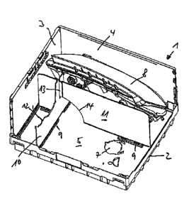
The figures show a transport container that is provided, in
general, with the reference symbol 1.
The transport container consists of a bottom part 2 and of side
walls 3 and 4 that rise from this bottom part 2, whereby the
side walls 3 are the shorter transverse side walls, and the side
walls 4 are the longer longitudinal side walls. In Figure 1,
the front longitudinal side wall and the front transverse side
wall are left out, for the sake of clarity of the illustration.
The bottom part 2 consists of an insert 5 that is shown in
greater detail in Figure 5. The bottom part 5 stands on the
CA 02769672 2012-01-31
WO 201 1/01 8211 PCT/EP2010/004897
9
actual bottom of the transport container 1 with ribs 6 that are
configured as spacers.
Recesses 7 are made in the bottom part 5, which serve to
accommodate an end part of transport goods, in this case of a
motor vehicle headlight 8.
An intermediate wall 10 and a partition wall 11 are disposed in
cross shape relative to one another, on the bottom part 5, by
means of hinges 9. The intermediate wall is configured in
accordance with the contours of the headlight 8 that is to be
accommodated in this case, at its upper edge 12.
A slit-shaped guide 13 is disposed in the center, in the
intermediate wall, which guide accommodates the partition wall
11. As is more clearly evident from Figure 2, the partition
wall has a recess 14 in the shape of a quarter circle, the
center point of which lies in the bottom part plane and through
the center point of which the pivot axis of the hinge 9 of the
intermediate wall 10 runs.
When the intermediate wall and the partition wall are folded
together, the intermediate wall is first folded down along the
CA 02769672 2012-01-31
WO 2011/018211 PCT/EP2010/004897
quarter-circle line. Afterward, the partition wall 11 is folded
down onto the intermediate wall.
In this position, the side walls 3 and 4, if they are
articulated onto the bottom part with hinges, can then also be
folded down onto intermediate and partition walls (see Fig. 7).
To fix the intermediate wall 10 and the partition wall 11 in
place, cam-shaped engagement elements 15 are provided on the
corresponding side walls 3 or 4. These engagement elements 15
consist of a ramp-like cam 17 that runs from the side wall
plane, at a slant, to a maximum, and from here in the direction
of the side wall plane, all the way to a stop 16. As a result
of the elastic properties of the walls, which are generally made
from plastic, the side edges of the intermediate wall 10 and the
partition wall 11, respectively, slide over the cams 17 and then
engage in front of the stop 16.
The part 8 to be transported is inserted into the recesses 7 in
the bottom part 2, on the one hand, and set onto the upper edge
12 of the intermediate wall 10.