Note: Descriptions are shown in the official language in which they were submitted.
CA 02769681 2012-01-31
WO 2011/022541
PCT/US2010/045995
Docket No.: KR2.0 17.PC
DUAL MODE REFLEX AND
TELESCOPIC SIGHT COMBINATION
BACKGROUND
[001] A reflex or "red dot" sight superimposes a
reticle, such as a simple red dot, on a typically
unmagnified target. The advantage of a reflex sight is that
it is theoretically parallax free, can be held at any
distance from the eye, and can be used with both eyes open.
Accordingly, the shooter may acquire a target without first
carefully placing his eye on an eye-piece, closing the
non-aiming eye and finding the target in a limited sight
field-of-view. This permits a short range shooter to
acquire a target far more rapidly than he could if looking
through a telescopic sight.
[002] At longer ranges (e.g. greater than 100 yards) it
becomes necessary to use a telescopic sight. Heretofore the
problem of installing both a reflex and a telescopic sight
on the same gun has not been entirely solved, with
suggested solutions sacrificing at least some optical
qualities or user convenience.
[003] From a more technical perspective, a reflex sight
collimates the light from a luminous reticle and
superimposes this light onto a view-window. This places the
reticle at an infinite range and virtually eliminates the
effects of parallax, when viewing a target that is
effectively at an infinite range. Frequently the
collimation is performed by a curved mirror that is placed
to the side of the path of the light passing through the
view-window. Unfortunately, the need to redirect the
collimated light reflecting from the curved mirror so that
CA 02769681 2012-01-31
WO 2011/022541
PCT/US2010/045995
2 Docket
No.: KR2.0 17.PC
it is superimposed on the view-window complicates the
design and tends to reduce performance.
SUMMARY
[004] In a first separate aspect, the present invention
may take the form of a combined reflex/telescopic sight
that includes a telescopic optical element train and a view
window, offset from the optical element train. A transition
assembly is positioned to receive light from the optical
element train and the view window. The transition assembly
has an image display, a collimating lens-set positioned to
transmit light to the image display and a luminous reticle.
This assembly may be placed in a first mode in which light
from the optical train travels through the collimating lens
set to the image display and light from the view window is
blocked. In a second transition assembly mode light from
the optical train is blocked and light from the luminous
reticle travels through the collimating lens set and is
combined with light from the view window and a resulting
combined image appears at the image display. Finally an
actuation assembly is adapted to permit a user to switch
the transition assembly between the first and second modes.
[005] In a second separate aspect, the present
invention may take the form of a telescopic sight that
includes a housing defining a centerline, an image output,
an optical train, within the housing, causing a reticle to
appear to a user looking through the image output. A
reticle position adjust mechanism has a reticle position
actuator that when manipulated by a user causes the reticle
CA 02769681 2012-01-31
WO 2011/022541
PCT/US2010/045995
3 Docket
No.: KR2.0 17.PC
to change position relative to the housing centerline.
Finally, a reticle position adjust mechanism lock, having a
lock actuator may be placed into either a locked position,
in which the reticle position actuator is locked in place
or an unlocked position, in which the reticle position
actuator may be moved.
[006] In a
third separate aspect, the present invention
may take the form of a method of switching from a reflex
sight to a telescopic that makes use of a combined
telescopic and reflex sight. This sight includes a view
window, a telescopic optical train, offset from the view
window, a collimating lens set and an image display adapted
to receive light from the collimating lens set, a luminous
reticle and a movable mirror placed in a first position
adapted to reflect light from the luminous reticle to the
collimating lens set and to block light from the telescopic
optical train from entering a light path leading to the
image display. The method includes the act of moving the
movable mirror from the first position to a second position
where it does not reflect light from the luminous reticle
but reflects light from the telescopic optical train into a
path leading to the image display and blocks light from the
view window.
[007] In a
fourth separate aspect, the present invention
may take the form of a method of making a rifle scope that
makes use of an element-retaining housing piece and a
mating, closure housing piece. Optical assemblies are
attached to the element-retaining piece and the mating,
closure housing piece is attached to the element-retaining
housing piece and the pieces are fastened together.
CA 02769681 2012-01-31
WO 2011/022541
PCT/US2010/045995
4 Docket
No.: KR2.0 17.PC
[008] In a fifth separate aspect, the present invention
may take the form of a rifle scope, comprising a straight
wall, defining an interior side and an exterior side and an
actuator, with an exterior, manual portion, moved along the
exterior side, and an interior portion, which moves along
the interior side as the exterior, manual portion is moved
along the exterior side.
[009] In a sixth separate aspect, the present invention
may take the form of a rifle scope having a first
longitudinal housing portion and a second longitudinal
housing portion matingly engaged to the first longitudinal
housing portion, thereby forming a housing having an
interior surface. A scope optical train is supported by the
first housing portion, and includes a zoom assembly having
a zoom assembly optical train of lenses. A windage and
elevation angle adjustment assembly is adapted to change
the position of the zoom assembly optical train of lenses.
The housing is arranged about the zoom assembly so that a
distance of greater than 5 mm exists between the housing
interior surface and the lenses of the zoom assembly
optical train.
[0010] In a seventh separate aspect, the present
invention may take the form of a rifle scope that has a
housing having a top and a bottom; an optical train
supported and protected by the housing; and an attachment
bracket on the bottom of the housing. An elevation adjust
mechanism includes an actuator positioned on the bottom of
the housing. Accordingly, the actuator does not obscure the
view of a scope user attempting to look over the scope.
CA 02769681 2012-01-31
WO 2011/022541
PCT/US2010/045995
Docket No.: KR2.0 17.PC
BRIEF DESCRIPTION OF THE DRAWINGS
[0011] Exemplary embodiments are illustrated in
referenced drawings. It is intended that the embodiments
and figures disclosed herein are to be considered
illustrative rather than restrictive.
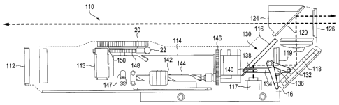
[0012] FIG. 1 is a perspective view of a dual mode sight
according to the present invention.
[0013] FIG. 2A is a side sectional view of the sight of
FIG. 1, in reflex mode.
[0014] FIG. 2B is a side sectional view of the sight of
FIG. 1, in telescopic mode.
[0015] FIG. 3 is a detail perspective view of the mirror
movement assembly of the dual mode sight of FIG. 1.
[0016] FIG. 4 is a detail perspective view taken along
line 4-4 of FIG. 1.
[0017] FIG. 5 is a top perspective view of a work piece
representing a stage in a preferred method of production
according to the present invention.
[0018] FIG. 6 is a top perspective view of the work
piece of FIG. 5, at a further stage in a preferred method
production according to the present invention.
[0019] FIG. 7 is a bottom cut-away view of the work
piece of FIG. 5, showing the elevation knob cover open.
CA 02769681 2012-01-31
WO 2011/022541
PCT/US2010/045995
6 Docket
No.: KR2.0 17.PC
[0020] FIG. 8 is a bottom cut-away view of a portion of
the work piece of FIG. 7, showing the elevation knob cover
closed.
[0021] FIG. 9 is a top perspective view of the work
piece of FIG. 6, at a further stage in a preferred method
production according to the present invention.
[0022] FIG. 10 is a top perspective view of the work
piece of FIG. 9, at a further stage in a preferred method
production according to the present invention.
[0023] FIG. 11 is a top-front perspective view of a dual
mode rifle sight, constructed as shown if FIGS. 5-10.
[0024] FIG. 12 is a top-rear perspective view of the
rifle sight of FIG. 11.
[0025] FIG. 13 is a longitudinal sectional view of the
rifle sight of FIG. 11.
[0026] FIG. 14 is a perspective view of an alternative
embodiment of a rifle sight according to the present
invention.
DETAILED DESCRIPTION OF THE PREFERRED EMBODIMENTS
[0027] Referring to FIG. 1, in a preferred embodiment a
dual mode sight 10 includes a reflex portion 12, a
telescopic portion 14 and a lever 16, to switch between the
use of these two portion 12 and 14. A zoom slider 18 and
slider slot 19 permit a user to change sight 10
magnification and an elevation knob 20 permits the reticle
CA 02769681 2012-01-31
WO 2011/022541
PCT/US2010/045995
7 Docket
No.: KR2.0 17.PC
position to be changed vertically, to compensate for the
anticipated effect of gravity on a fired bullet. A windage
knob is hidden from view on the right side of the sight 10
(from the user's perspective), and may be used to change
the reticle position horizontally, to compensate for the
anticipated effect of wind on a fired bullet. An elevation
knob lock 22 can be pushed in to lock the elevation knob in
place, to avoid instances in which a piece of vegetation
brushes against knob 20 and causes it to move, degrading a
previous adjustment. A windage knob lock is hidden from
view, on the right side of the sight 10. Also, a reticle
illumination button 24 can be pushed in to cause the
illuminated reticle for the reflex sight mode to light up.
A side rack 26, permits the attachment of supporting
devices.
[0028] Referring to FIGS. 2A and 2B, sight 10 includes
an optical train 110, including a telescopic sight
objective lens 112, a Petzval lens 113 (pedestal support
not shown) and an erector/cam tube 114. In the reflex sight
mode shown in FIG. 2A, however, the light from erector tube
114 is blocked by a moveable mirror 116, which reflects
light from red luminous reticle 117 into a collimating lens
set 119, with a fixed mirror 118, redirecting the light by
90 between the two lens groupings of lens set 119. A
red-reflecting mirror 120, redirects the red reticle light
by 90 and combines it with light from view window 124,
which passes through mirror 120. Because the light from
reticle 117 passes through the collimating lens set 119, it
does not need to be collimated by a dish-shaped mirror, as
is the case with some prior art configurations. This
CA 02769681 2016-08-24
8
permits a high quality sight design that is easily
manufactured.
[0029] Referring to FIG. 2A, when the sight 10 of FIG. 1
is placed into telescopic sight mode moveable mirror 116 is
moved into the position shown, where it does not block
light from erector tube 114, but rather reflects this light
through an image display 126. Also, mirror 116 is not in
position to reflect the light from reticle 117 into the
path that is reflected out of the image display 126.
Collimating lens set 119 serves double duty, collimating
light from the reflex reticle in reflex mode and from
telescopic optical train 110 in the telescope sight mode.
In telescopic sight mode a reticle appears to the viewer,
created by a reticle element in the erector tube 114, in
traditional configuration.
[0030] Referring to FIG. 2A, 2B and 3, in one preferred
embodiment dual mode sight 10 has a mirror movement
assembly 130 to switch between reflex mode (FIG. 2A) and
telescopic mode (FIG. 2B). User control lever 16 is rigidly
attached to a hidden arm 132, which is hinged to a mirror
movement lever 134 at a first hinge 133. Lever 134 is also
hinged to a fixed point in sight 10, at a second hinge 136
and includes a slot 138 to allow some freedom of movement
for a mirror pin 140.
[0031] Starting at the telescopic sight mode position
shown in FIGS. 2B and 3, as lever 16 is moved rearward,
hinge point 133 is moved upwardly, causing lever 134 to
pivot about hinge 136 until hinge point 133 has risen and
slot 138 has fallen, and lever 134 is in the horizontal
position shown in FIG. 2A. Note that as lever 134 is moved
CA 02769681 2016-08-24
9
into the horizontal position, mirror pin 140 must move
inwardly in slot 138 for mirror 116 to retain its oblique
orientation.
[0032] Zoom slider 18 (FIG. 1) is attached to a slider
142 (FIGS 2A and 2B) via slider slot 19. Slider 142 rotates
a pole 144 as it is moved back and forth, which in turn
rotates a gear 146, which turns erector/cam tube 114,
thereby changing erector lens positioning, by way of the
well-known technique of cam followers in cam slots.
[0033] Elevation knob 20 is operatively connected to
erector/cam tube 114 and pushes it to a further down
position depending on how far knob 20 is rotated. An
erector tube spring 147 resists this downward adjustment,
pushing upwardly against tube 114. Windage adjust mechanism
(not shown) works in the same way, and is also resisted by
spring 147. A click ring 148 moves past a clicker post 150,
causing a set of click sounds as knob 20 is turned, thereby
informing a schooled user of the change in elevation
adjustment.
[0034] Referring to FIG. 4, the elevation knob lock 22,
noted above, is described in greater detail here. Lock 22
is actually a post that extends through sight 10, so that
it always protrudes from either the left or right side of
sight 10, and may always be pushed in from whatever side it
is protruding. Lock post 22 defines two indents, an unlock
indent 151 and a locking indent 152. When unlock indent 151
is aligned with a lock pin 154, an intermediate ball 156
can retract into indent 151, which is deep enough so that
lock pin 154, which is urged into the indent by a spring
158, will not engage with the click ring 148. Locking
CA 02769681 2012-01-31
WO 2011/022541
PCT/US2010/045995
Docket No.: KR2.0 17.PC
indent 152 is so shallow, however, that ball 156 is pushed
into lock pin 154, which engages with click ring 148,
thereby locking the elevation knob 20.
[0035] In one preferred embodiment objective lens 112 is
32 mm in diameter, but in an alternative preferred
embodiment it is rectangular and is 40 mm in width. The
reflex reticle is a 60 minute of angle (MOA) diameter
circle with a 1 MOA dot in the center.
[0036] In another separate aspect, the present invention
may take the form of a method of constructing a rifle
sighting system 208 (FIGS. 11 and 12) that is similar to
that shown in FIG. 1-4, also being a dual mode
reflex/telescopic sight, and to which the manufacturing
techniques described below could be applied equally as
well. In one preferred embodiment construction begins (see
FIG. 5-9) with a work piece 210, which in its first form is
a mounting assembly 212. Assembly continues with the
attachment of a mode switching and ocular assembly 214
(FIG. 6), which switches the scope between a reflex sight
mode and a telescopic sight (scope) mode and also presents
the imagery to a viewer. In addition a zoom assembly 216
(FIG. 9) is attached. Assembly 216 has the function of user
actuated variable magnification (that is, "zoom") and also
is tilted to introduce an elevation angle for bullet drop
correction and a windage angle. Finally an objective lens
and Petzval assembly 218 (FIG. 10) is mounted, to accept
light for the telescopic portion of the scope and to
refract this light in accordance with the overall optical
scheme. Finally, a cover 220 (FIGS. 11 and 12) is placed on
the work piece and fastened securely in place, to create a
CA 02769681 2012-01-31
WO 2011/022541
PCT/US2010/045995
11 Docket
No.: KR2.0 17.PC
finished sighting system 208. In addition to various
elements described below, FIG. 11 and 12 show a windage
knob 221, the operation of which will be familiar to
skilled persons and the action of which is identical with
elevation knob 238, which is discussed below. In an
alternative preferred embodiment, two cover pieces are
used, to form a sight that has less of a regular shape.
[0037] The method of constructing a rifle sight 208 by
attaching a set of pre-built assemblies to a mounting
assembly divides the assembly process into smaller and more
easily automated tasks. Also, this method permits a design
having more space for the zoom assembly, permitting a
stronger construction of this assembly that is therefore
better able to withstand recoil shock. Finally, designs are
permitted that more easily accommodate other internal
parts, such as internal portions of actuator assemblies.
[0038] In greater detail of mounting assembly 212, a
mounting plate 222 is adapted to receive optical
assemblies, as will be described below. A rifle mounting
fixture 224 supports mounting plate 222 and is adapted to
permit the finished scope 208 to be attached to a rifle
(not shown). Mounting plate 222 includes many mounting
features, such as a set of fastener-receiving holes 226 to
permit the mounting of optical assemblies and other
elements. Also, a front indentation 228 helps guide the
placement of the objective assembly 218 (FIG. 10) and in
use helps absorb the shock of recoil, which over time may
damage fasteners. A rear, essentially square through-hole
230 (FIG. 5), is adapted to host a light emitting diode
(LED) based reflex sight reticle 229 (FIG. 13). A set of
CA 02769681 2012-01-31
WO 2011/022541
PCT/US2010/045995
12 Docket
No.: KR2.0 17.PC
long threaded apertures 231 (FIG. 5), permit adjustment
screws 233 (FIG. 13) to be used to make small changes to
the position of the reflex reticle 229.
[0039] At the stage of production shown in FIG. 5, a cam
tube-turning gear 232 and an arm 234 that rotates gear 232
are already attached to plate 222. Also, a dual mode
switching-lever 236 is hinged to plate 222. Additionally
present is an elevation angle actuator knob 238, which is
protected against accidental contact by a knob cover 239
(see also FIGS. 7 and 8). In turn, cover 239 is retained by
a sliding latch 240. In a preferred embodiment, a cam tube
base support 242 is part of plate 222, and a cam tube side
support 244 is fastened to plate 222. An elevation
adjustment post 248, driven by actuator knob 238, protrudes
from an aperture in support 242, and as will be familiar to
skilled persons, is used to change the elevation angle of
the cam tube assembly 216.
[0040] Referring to FIG. 6, pre-built mode switching and
ocular assembly 214 is installed at the rear of mounting
assembly 220 using fastener apertures 226. In addition,
dual mode switching lever 236 is connected to assembly 214.
[0041] Referring to FIG. 9, in a next step in the
assembly process, a cam tube assembly 216, including a cam
tube assembly holder 262, is installed, by bolting holder
262 onto plate 222, using bolts that come up through plate
222 into threaded holes in holder 262. The front portion of
assembly 216 rests on cam tube elevation post 246 and cam
tube side support 244. The gear 232 meshes with a cam tube
assembly gear 266 to turn assembly 216. Base plate 222
defines an opening through which a pin 268 (FIG. 13)
CA 02769681 2012-01-31
WO 2011/022541
PCT/US2010/045995
13 Docket
No.: KR2.0 17.PC
extends connecting arm 234 to gear 232. This opening is
only required to be large enough to accommodate pin 268,
which fits snugly. As a result, scope 208 is sealed tightly
against outside elements, which are not afforded an
opportunity for entry by the zoom actuator (collectively
arm 234, pin 268 and gear 232). Spring 270, connecting
fixed arm 271 with connected to mirror 290 (FIG. 13), urges
mirror 290 to quickly move to its correct position during
switching of lever 236 (see discussion of FIG. 13).
[0042] Referring to FIG. 10, an objective and Petzval
lens assembly 218 is fit into recess 228 and attached using
apertures 226. An objective lens support 272 hosts a set of
objective lenses 274, a lens-protective clear sheet 275,
and a Petzval support 276 hosts Petzval lens holder 278
that, defining slots 282, in turn holds Petzval lens 280.
Additionally, assembly 218 includes a set of braces 284
which retain the front of cam tube assembly 216, in
cooperation with elevation post 246 and side support 244 or
windage post (not shown).
[0043] Referring to FIGS. 11 and 12, the cover 220 is
placed over assemblies 214, 216 and 218 and connected to
plate 222 by fasteners placed through base plate cover
fastening apertures 292 and into apertures (not shown)
defined in the bottom of the sides of cover 220. The
housing of sight 208 is formed from the fastened together
combination of plate 222 and cover 220. Cover 220 defines a
reflex sight window 314 and an image presentation window
316. A reflex reticle brightness adjustment knob 320 is
electrically connected to reflex reticle 29.
CA 02769681 2012-01-31
WO 2011/022541
PCT/US2010/045995
14 Docket
No.: KR2.0 17.PC
[0044] Referring to FIG. 13, assemblies 214, 216 and 218
cooperate together to provide a dual mode reflex/telescopic
sight 208 having a user controlled variable magnification
(also referred to as "zoom"). Lever 236 (FIGS. 9 and 10) is
operatively connected to and changes the position of a
moveable mirror 290, 290', between a reflex sight mode
position 290 and telescopic sight mode position 290'. In
reflex sight mode position, light from the light emitting
diode (LED) reflex sight reticle 29, housed in square
aperture 230, is reflected from mirror 290 and through a
first ocular lens 294. The reticle light is then reflected
from a fixed mirror 296 and travels through a second ocular
lens 298. This light is then reflected from the reflex
sight window 314, the back side of which is reflective for
the red light of the reflex sight reticle, through image
presentation window 316 to the user. Accordingly the
reticle image is superimposed upon the view from window
314. In telescopic sight mode, the moveable mirror 290 is
in telescopic sight mode position 290', where it blocks the
light from window 314 and reflects the light that has
traveled through zoom assembly 216, including a reticle
267, and ocular assembly 214.
[0045] Assembly 216 includes a pair of lens groups 321,
each of which is held in a lens holder 322 that supports a
slot-follower 324. Lens groups 321 are supported by two
concentric tubes, an inner tube 326 and a cam tube 328,
concentric with and supporting inner tube 326. Inner tube
326 defines a straight longitudinal slot 330, whereas cam
tube 328 defines curved cam-slots 332. Slot-followers 324
each engage with both slot 330 and one of slots 332.
Accordingly, as cam tube 328 is turned by gear 232, lens
CA 02769681 2012-01-31
WO 2011/022541
PCT/US2010/045995
15 Docket
No.: KR2.0 17.PC
groups 321 move forward or backward, but retain their
orientations.
[0046] Referring to FIG. 14, in an alternative preferred
embodiment, cam tube 328 is turned by a gear 140 driven by
an electric motor, inside a housing 142, and actuated by a
button 144. The electric motor may be supported by a set of
springs or resiliently deformable material with housing
330, to protect the motor against recoil shock.
[0047] One advantage of the method of the present
invention is that assemblies 214, 216, and 218 may be
constructed and tested separately, thereby dividing the
assembly task into three simpler tasks of sub-assembly
construction, which may be automated, and a final assembly
that requires only the installation of the three
assemblies, and final testing and adjustment. Final test
and adjustment is critical, however, so that the reticle
will be in focus at every variable magnification level.
[0048] Assemblies 214 and 218 include features designed
to facilitate the final adjustments. The Petzval lens
holder 278 has a threaded exterior that engages with a
threaded interior of support 276, and may be moved forward
or rearward by rotation. Slots 282 accept a tool to
facilitate such rotation. Similarly, ocular lens 294 is
mounted onto holder 350, which is fastened by threaded
fasteners to base 352. During assembly a technician
positions lens 294 by moving holder 350 as he looks through
the image presentation window 116 until the telescopic
reticle (not shown) appears clearly in focus at -3/4
diopters. After holder 350 is correctly position a number
of fasteners, including one from the front that acts as a
CA 02769681 2012-01-31
WO 2011/022541
PCT/US2010/045995
16 Docket
No.: KR2.0 17.PC
hard stop during recoil are utilized to keep holder 350 and
lens 294 securely in place.
[0049] It should be emphasized that although the
preferred embodiment shown is a dual mode reflex/telescopic
sight 208, that the method of constructing a scope is
equally applicable to a single mode telescopic sight, or
stated in more familiar terms, a rifle scope. Skilled
persons may now appreciate some of the advantages of the
present design. Each of the three assemblies 214, 216 and
218 may be assembled and tested prior to final assembly,
thereby reducing the critical tasks of final assembly to
the installation of these three assemblies into the
prepared attachment locations and final adjustments.
[0050] In prior art scope assemblies, a difficulty is
encountered in attaching a typical round scope to an
essentially flat mounting rail. The mounting rings used to
solve this problem create their own problems by limiting
the areas available for scope controls. A conflict is
sometimes encountered between the location of the scope
controls and the mounting rings. The present design
entirely eliminates this problem, by eliminating the need
for mounting rings.
[0051] The basic design of the zoom actuator (arm 234,
gear 232 and gear 266), may be used for rifle scopes having
differing configurations. For example, in an alternative
preferred embodiment, the same construction techniques are
used to build a scope having a focus adjustment. In this
case, however, the arm may turn a noncircular gear, to
achieve a nonlinear relationship between arm movement and
focus lens movement.
CA 02769681 2016-08-24
17
[0052] One problem encountered in prior art scope design
is that of the lack of transverse space available for the
cam tube and the pivot tube (generally analogous to outer
tube 306 and inner tube 304 of the present preferred
embodiment, but with various permutations, such as the cam
tube being nested inside the pivot tube. This lack of space
led to cam tube designs with wall thickness of less than a
millimeter, leaving the cam tube vulnerable to damage from
the slot followers during recoil. The present design does
not put a transverse space limitation on cam tube and pivot
tube wall thicknesses, making for a more robust design with
wall thicknesses of 1 mm or greater. Accordingly with this
basic manufacturing scheme, scopes can be made that are
able to withstand the recoil of more powerful rifles, such
as .50" caliber rifles.
[0053] Moreover, many additional preferred embodiments
utilize the interior space made available through the
construction techniques of the present method. In one
design, electric motors directly move the lens groups in
the zoom assembly, thereby creating a greater range of
possible zoom ratios.
[0054] While a number of exemplary aspects and
embodiments have been discussed above, those possessed of
skill in the art will recognize certain modifications,
permutations, additions and sub-combinations thereof. It is
therefore intended that the scope of the claims should not be
limited by the preferred embodiments set forth in the examples,
but should be given the broadest interpretation consistent with
the description as a whole.